US1856672A - Controlling means for coil winding machines and the like - Google Patents
Controlling means for coil winding machines and the like Download PDFInfo
- Publication number
- US1856672A US1856672A US357941A US35794129A US1856672A US 1856672 A US1856672 A US 1856672A US 357941 A US357941 A US 357941A US 35794129 A US35794129 A US 35794129A US 1856672 A US1856672 A US 1856672A
- Authority
- US
- United States
- Prior art keywords
- machine
- lever
- switch
- wires
- bar
- Prior art date
- Legal status (The legal status is an assumption and is not a legal conclusion. Google has not performed a legal analysis and makes no representation as to the accuracy of the status listed.)
- Expired - Lifetime
Links
- 238000004804 winding Methods 0.000 title description 7
- 239000011435 rock Substances 0.000 description 5
- 239000011521 glass Substances 0.000 description 4
- 239000011810 insulating material Substances 0.000 description 3
- 239000002184 metal Substances 0.000 description 3
- 230000002950 deficient Effects 0.000 description 2
- 230000000994 depressogenic effect Effects 0.000 description 2
- 230000000694 effects Effects 0.000 description 2
- 239000012774 insulation material Substances 0.000 description 2
- 238000004519 manufacturing process Methods 0.000 description 2
- 230000004048 modification Effects 0.000 description 2
- 238000012986 modification Methods 0.000 description 2
- 230000010355 oscillation Effects 0.000 description 2
- 230000000284 resting effect Effects 0.000 description 2
- 101001005711 Homo sapiens MARVEL domain-containing protein 2 Proteins 0.000 description 1
- 208000003251 Pruritus Diseases 0.000 description 1
- 230000015572 biosynthetic process Effects 0.000 description 1
- 238000010276 construction Methods 0.000 description 1
- 230000005484 gravity Effects 0.000 description 1
Images

Classifications
-
- B—PERFORMING OPERATIONS; TRANSPORTING
- B21—MECHANICAL METAL-WORKING WITHOUT ESSENTIALLY REMOVING MATERIAL; PUNCHING METAL
- B21F—WORKING OR PROCESSING OF METAL WIRE
- B21F3/00—Coiling wire into particular forms
Definitions
- the present invention relates to improved controlling means for coil winding machines and the like, and has forits primary object the provision of improved means for controlling the operation of such machines so as to prevent errors or imperfections in the output, the present invention being especially adapted and arranged for use in conjunction with such machines as are illustrated in my prior Patent No. 1,482,592, dated February 5, 1924.
- Another object of the invention is to provide an arrangement for use in conjunction with such machines whereby breaking of one of the wires going into one of the coils being wound on said machine, will result automatically in stopping the machine and thereby prevent the forming of a defective or imperfect coil.
- Another object of the invention is to provide a simple and eflicient attachment for machines of this character which is capable of economical production and is highly eflicient in use.
- Another object of the invention is the provision of an improved switch lever for use in conjunction with machines of this character.
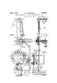
- FIG. 1 is a partial side view of an arrangement embodying the invention
- Fig. 2 a partial front elevation of the same
- Fig. 3 a partial top plan view of the same
- FIG. 5 an enlarged section taken substantially on line 5-5 of Fig. 4;
- Fig. 7 a detail view illustrating a wiper member employed in the machine
- Fig. 8 a section taken substantially on line 8-8 of Fig. 1;
- Fig. 9 a detail view of one of a plurality 1929. Serial No. 357,941.
- Fig. 1 I have illustrated diagrammatically the motor circuit for operating such a machine, said circuit being identified by the reference numeral 11 and including therein an electric motor 12 for operating the machine in the usual way, as will be readily understood by those skilled in this art.
- a usual form of starting box or rheostat comprising a hand lever 13 having an operating handle 14 and cooperating with contact points 15 and resistance coils 16 to operate as a starting box or switch for the motor 12 of the machine.
- the rheost-at is also provided with the usual dead or idle contact point 17 and the arrangement is such that when the lever 13 is over and in operative relationship with the contact 17, the motor circuit is broken and the machine stopped.
- the lever 13 is also provided with usual spring 13 by means of which said lever is thrown to open or circuit breaking position when re leased.
- the lever 13 is also provided with a downwardly projecting detent nose 18 best shown in Fig. 1, and cooperating with a detent bar 19 on the spring held armature 20 of an ordinary electro-magnet 21.
- the arrangement is such that when the lever 13 is swung to the right or into operative position, the nose 18 engages the detent bar 19 and said lever is thus held in circuit closing position, but when the armature 20 is depressed, the lever 13 is released and is then thrown by the spring 13' into its extreme left hand position to break the motor circuit.
- the electro-magnet 21 is included in an electric controlling circuit 22, as best shown 1 in Figsl and 6.
- the circuit 22 also includes, in parallel with the electro-inagnet 21, a push switch 23 connected in said circuit by means of the branch wires 24 and whereby, when said push switch is closed, current will be caused to flow through the electro-magnet 21, the detent bar 19 withdrawn and the machine stopped. This furnishes a simple and convenient means for manually stopping the ma chine by the operator thereof when desired.
- One of the wires 22 of said controlling circuit also leads to a binding post 25 on a triangular plate or bracket 26 of insulating material secured to the corresponding side bar of the bracket 10, by means of screw bolts 27 as shown.
- T he other wire of the circuit 22 is connected with a binding post 28 also mounted on the insulating plate 26 closely adjacent to the binding post 25.
- a handle lever 29 also of insulating material, and rigidly secured to one end of a metal rock shaft 30 mounted transversely in the bracket 10.
- the lever 29 co-operates with the stop pin 31 on the bracket 26 which limits upward swinging of said lever and another stop pin 32 on said lever is arranged to engage with the corresponding side bar of the bracket 10 to limit downward swinging thereof.
- the upper position of the lever 29 is indicated in full lines in Fig. 6, and the lower position thereof is indicated by dotted lines in the same view of the drawings.
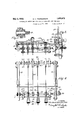
- a plurality of switch levers are loosely mounted on the rocker shaft 30, each of said switch levers comprising an oblong metal body 33 carrying two projecting co-operating oppositely disposed spring arms 34. At their outer ends, the arms 34 are provided with inwardly extending points or projections 35, see Fig. 9, adapted and arranged to engage in the ends of a glass tube 33, thereby furnishing a simple and convenient means for mounting said glass tubes in said switch levers.
- the metal bodies 33 are eccentrically mounted, as shown, on the rocker shaft 30 to rock loosely on said shaft being adjustably held in position by means of collars 37 placed on opposite sides thereof, as best shown in Fig. 4.
- the unbalanced weight of the body 33 of each switch lever is sufficient to cause upward swinging of the switch arms 34 when released.
- the rocker shaft 30 also carries a setting rod 38 rigidly attached thereto by means of arms 39 imprisoned between lock nuts 40 and whereby the setting rod 38 will be caused to rock with the shaft 30.
- a supporting shaft 41 Arranged in the bracket 10 above the rocker shaft 30, is a supporting shaft 41, on which is mounted a plurality of grooved guide pulleys '42 positioned between collars 43, and whereby said guide pulleys are adjustably mounted so as to be free to rotate on said supporting shaft.
- the wires 44 for forming the coils in the coil winding machine are led into the machine over the guide pulleys 42, there being one of said guide pulleys provided for each wire thus led into the machine.
- the guide pulleys 42 may be adjusted as desired on the supporting shaft 41 to effect various arrangements of the wires and also more or less of said guide pulleys may be provided so as to provide for more or less wires as desired.
- the wires 44 are led downwardly from the guide pulleys 42 to pass between felt wipers 45 and 46.
- the wiper 45 is supported on suitable brackets '47 from the supporting shaft 41 and the wiper 46 is supported on swinging arms 48 as shown and whereby the wiper 46 may beswung upward- 1y as indicated in Fig. 7 to facilitate the threading of the wires between said wipers.
- the wires pass from the wiper members 45 and 46 substantially vertically downwardly into the machine.
- the of the switch levers 3334 is provided for each of the wires 44 and the glass tube 36 thereof is rested against the corresponding wire, so that the tension of sai wire normally holds the switch lever in tilted position with the glass tube 36 extending downwardly as shown in l and 6.
- the arrangement is such, however, that in case of break age of any one of the wires 44, such, 1 s for example, the wire 44, which is indicated as broken in Fig. 6, the corresponding s *itch lever will swing upwardly, also as indicated in Fig. 6.
- a stop bar 49 is mounted one one. i the bracket 26 and at its other end in the bracket '50 on the other side bar of the bracket 10, said stop bar 49 being mounted in position to limit the upward swing of the switch levers 3334, as best indicated in Fig. 6.
- the stop bar 49 is extended at one enn through the bracket 26 as best shown in Fig. 3.
- a metallic switch plate 52 is secured to the handle lever 29 as shown, and provided with switch contact memb s 53 and 54 arranged to engage the hind g post 25 and the end 51 of the stop bar 49 whe .i said handle is swung upwardly into horizontal position, as best shown in Fig.
- the contact member 56 is connected by a bar 57 with the rock shaft 30, as bestshown in Figs. 1. and 3.
- circuit 22 is completed through that switch lever and the bar 49 and the rock shaft 30 so that electro-magnet 21 will be excited to withdraw the detent bar 19 and thereby stop the machine.
- electro-magnet 21 will be excited to withdraw the detent bar 19 and thereby stop the machine.
- the handle lever 29 When it is desired to rethread one or more of the wires into the machine, the handle lever 29 is rocked downwardly, as indicated by the dotted lines in Fig. 6, whereby the switch levers are all depressed, thus facilitating the threading of the wires through the machine;
- two sleeves 58 of insulating material are provided for the rod 49 so that, when desired, saidsleevesmaybemounted on said rod to render the corresponding switch levers inoperative and thus permit the i operation of the machine with a smaller number of wires and switch levers.
- the tubes 58 are removed from the machine.
- the machine thus provided is capable of operation at high speed and will operate with great efficiency to stop the same automatically in case of the breaking of any one of the wires employed in the machine.
- a machine of the class described comprising a motor circuit for operating the machine; a supporting bracket; a plurality of grooved guide pulleys mounted on said bracket; a corresponding plurality of flexible strands passing over said guide pulleys and into said machine along definite paths; a supporting rod in said bracket adjacent the paths of said strands and electrically insulated from the bracket; a plurality of weighted switch levers arranged to oscillate freely on said rod and each carrying a contact member of insulation material resting against one of said strands and heldfrom oscillation thereby; a contact bar set to be engaged by swinging of any one of said switch levers upon release by breakage of its associated strand; a control circuit con- 2.
- a switch lever for machines of the class described comprising a weighted body mounted to oscillate by gravity; a pair of spring clamping arms mounted on said body and projecting therefrom in co-operative relationship, the ends of said arms being turned inwardly toward each other to form short inwardly extending projections and a non-conducting tube inserted between said arms with said projections engaging into the ends of the tube.
- a machine of the class described including means to normally maintain under tension a plurality of strands while being individually supplied for coiling, a plurality of levers supported for rotation in a position to rest upon the strands under tension, a contact bar, supported to be engaged by any one of said levers when the tension on any strand is relieved to permit rotation of the lever associated therewith, a motor for operating the machine, circuits for said motor including said levers and contact bar, means in said circuits for deenergizing the motors when the tension is relieved on any strand to permit the corresponding lever to engage the contact bar and means for raising all of said levers to permit threading of the strands.
Landscapes
- Engineering & Computer Science (AREA)
- Mechanical Engineering (AREA)
- Tension Adjustment In Filamentary Materials (AREA)
Description
. May 3,1932. c; H. THORDARSON 1,356,672
CONTROLLING MEANS FOR COIL WINDING MACHINES AND THE LIKE Filed April 25, 1929 s Sheets-Sheet 2 3' INVENTORI L 56 Cfiesieriimarcfizrvofl A TTORNEY.
May 3, 1932.- c. H. THORDARSON CONTROLLING MEANS FOR COIL WINDING MACHINES AND THE LIKE Filed April 25, 1929 3 Sheets-Sheet INVEN TOR. Cfieszerfiffzardafsom A TTORNEY Patented May 3, 1932 -Nrran STATES PATENT orricr.
CHESTER H. THORDARSON, OF CHICAGO, ILLINOIS, ASSIGNOR TO THORDARSON ELEC- TRIC MANUFACTURING COMIEANY, OF CHICAGO, ILLINOIS, A CORPORATION OF ILLINOIS CONTROLLING MEANS FOR COIL WINDING MACHINES AND THE LIKE Application filed April 25,
The present invention'relates to improved controlling means for coil winding machines and the like, and has forits primary object the provision of improved means for controlling the operation of such machines so as to prevent errors or imperfections in the output, the present invention being especially adapted and arranged for use in conjunction with such machines as are illustrated in my prior Patent No. 1,482,592, dated February 5, 1924.
Another object of the invention is to provide an arrangement for use in conjunction with such machines whereby breaking of one of the wires going into one of the coils being wound on said machine, will result automatically in stopping the machine and thereby prevent the forming of a defective or imperfect coil.
Another object of the invention is to provide a simple and eflicient attachment for machines of this character which is capable of economical production and is highly eflicient in use.
Another object of the invention is the provision of an improved switch lever for use in conjunction with machines of this character.
Other objects will appear hereinafter.
The invention consists in the combinations and arrangements of parts hereinafter described and claimed.
The invention will be best understood by reference to the accompanying drawings forming a part hereof and in which Fig. 1 is a partial side view of an arrangement embodying the invention;
Fig. 2, a partial front elevation of the same;
Fig. 3, a partial top plan view of the same;
Fig. 4, a partial rear View of the same;
Fig. 5, an enlarged section taken substantially on line 5-5 of Fig. 4;
Fig. 6, another side View of the attachment;
Fig. 7 a detail view illustrating a wiper member employed in the machine;
Fig. 8, a section taken substantially on line 8-8 of Fig. 1; and
Fig. 9, a detail view of one of a plurality 1929. Serial No. 357,941.
part of the main frame of the machine. The
attachment is designed and intended for use in conjunction. with a machine for winding coils and which is operated by an electric motor. In Fig. 1, I have illustrated diagrammatically the motor circuit for operating such a machine, said circuit being identified by the reference numeral 11 and including therein an electric motor 12 for operating the machine in the usual way, as will be readily understood by those skilled in this art. Included in the motor circuit, is a usual form of starting box or rheostat comprising a hand lever 13 having an operating handle 14 and cooperating with contact points 15 and resistance coils 16 to operate as a starting box or switch for the motor 12 of the machine. The rheost-at is also provided with the usual dead or idle contact point 17 and the arrangement is such that when the lever 13 is over and in operative relationship with the contact 17, the motor circuit is broken and the machine stopped. The lever 13 is also provided with usual spring 13 by means of which said lever is thrown to open or circuit breaking position when re leased.
The lever 13 is also provided with a downwardly projecting detent nose 18 best shown in Fig. 1, and cooperating with a detent bar 19 on the spring held armature 20 of an ordinary electro-magnet 21. The arrangement is such that when the lever 13 is swung to the right or into operative position, the nose 18 engages the detent bar 19 and said lever is thus held in circuit closing position, but when the armature 20 is depressed, the lever 13 is released and is then thrown by the spring 13' into its extreme left hand position to break the motor circuit.
It will be noted that, by this arrangement, when the electro-magnet 21 is excited, lever 13 will be released and the motor 12 and the ma chine driven thereby, automatically stopped.
The electro-magnet 21 is included in an electric controlling circuit 22, as best shown 1 in Figsl and 6. The circuit 22 also includes, in parallel with the electro-inagnet 21, a push switch 23 connected in said circuit by means of the branch wires 24 and whereby, when said push switch is closed, current will be caused to flow through the electro-magnet 21, the detent bar 19 withdrawn and the machine stopped. This furnishes a simple and convenient means for manually stopping the ma chine by the operator thereof when desired.
One of the wires 22 of said controlling circuit also leads to a binding post 25 on a triangular plate or bracket 26 of insulating material secured to the corresponding side bar of the bracket 10, by means of screw bolts 27 as shown.
T he other wire of the circuit 22 is connected with a binding post 28 also mounted on the insulating plate 26 closely adjacent to the binding post 25.
Co-operati'n'g with the binding posts 25 and 28 is a handle lever 29, also of insulating material, and rigidly secured to one end of a metal rock shaft 30 mounted transversely in the bracket 10.
The lever 29 co-operates with the stop pin 31 on the bracket 26 which limits upward swinging of said lever and another stop pin 32 on said lever is arranged to engage with the corresponding side bar of the bracket 10 to limit downward swinging thereof. The upper position of the lever 29 is indicated in full lines in Fig. 6, and the lower position thereof is indicated by dotted lines in the same view of the drawings.
A plurality of switch levers are loosely mounted on the rocker shaft 30, each of said switch levers comprising an oblong metal body 33 carrying two projecting co-operating oppositely disposed spring arms 34. At their outer ends, the arms 34 are provided with inwardly extending points or projections 35, see Fig. 9, adapted and arranged to engage in the ends of a glass tube 33, thereby furnishing a simple and convenient means for mounting said glass tubes in said switch levers. The metal bodies 33 are eccentrically mounted, as shown, on the rocker shaft 30 to rock loosely on said shaft being adjustably held in position by means of collars 37 placed on opposite sides thereof, as best shown in Fig. 4.
The unbalanced weight of the body 33 of each switch lever is sufficient to cause upward swinging of the switch arms 34 when released.
The rocker shaft 30 also carries a setting rod 38 rigidly attached thereto by means of arms 39 imprisoned between lock nuts 40 and whereby the setting rod 38 will be caused to rock with the shaft 30.
Arranged in the bracket 10 above the rocker shaft 30, is a supporting shaft 41, on which is mounted a plurality of grooved guide pulleys '42 positioned between collars 43, and whereby said guide pulleys are adjustably mounted so as to be free to rotate on said supporting shaft.
The wires 44 for forming the coils in the coil winding machine, are led into the machine over the guide pulleys 42, there being one of said guide pulleys provided for each wire thus led into the machine. Obviously, the guide pulleys 42 may be adjusted as desired on the supporting shaft 41 to effect various arrangements of the wires and also more or less of said guide pulleys may be provided so as to provide for more or less wires as desired. The wires 44 are led downwardly from the guide pulleys 42 to pass between felt wipers 45 and 46. The wiper 45 is supported on suitable brackets '47 from the supporting shaft 41 and the wiper 46 is supported on swinging arms 48 as shown and whereby the wiper 46 may beswung upward- 1y as indicated in Fig. 7 to facilitate the threading of the wires between said wipers.
As will be noted, the wires pass from the wiper members 45 and 46 substantially vertically downwardly into the machine. the of the switch levers 3334 is provided for each of the wires 44 and the glass tube 36 thereof is rested against the corresponding wire, so that the tension of sai wire normally holds the switch lever in tilted position with the glass tube 36 extending downwardly as shown in l and 6. The arrangement is such, however, that in case of break age of any one of the wires 44, such, 1 s for example, the wire 44, which is indicated as broken in Fig. 6, the corresponding s *itch lever will swing upwardly, also as indicated in Fig. 6.
A stop bar 49 is mounted one one. i the bracket 26 and at its other end in the bracket '50 on the other side bar of the bracket 10, said stop bar 49 being mounted in position to limit the upward swing of the switch levers 3334, as best indicated in Fig. 6.
The stop bar 49 is extended at one enn through the bracket 26 as best shown in Fig. 3. A metallic switch plate 52 is secured to the handle lever 29 as shown, and provided with switch contact memb s 53 and 54 arranged to engage the hind g post 25 and the end 51 of the stop bar 49 whe .i said handle is swung upwardly into horizontal position, as best shown in Fig.
The contact member 56 is connected by a bar 57 with the rock shaft 30, as bestshown in Figs. 1. and 3. By this arrangement. will be noted, that as each switch lever 3? swings upwardly after being released by l. breaking of the corresponding wire, it come-.7. into contact with the lower side of the bar 49. When the machine is in operation, the handle lever 29 is raised into its hori- Zontal position, so that when one 'of'the switch levers thus contacts with the stop bar 49, the
When it is desired to rethread one or more of the wires into the machine, the handle lever 29 is rocked downwardly, as indicated by the dotted lines in Fig. 6, whereby the switch levers are all depressed, thus facilitating the threading of the wires through the machine;
5/ When the handle lever 29 is restored to horizontal position, the switch levers will be brought back again into contact with the wires i l by which they are held until breaking of one of said wires as indicated above.
For convenience, two sleeves 58 of insulating material are provided for the rod 49 so that, when desired, saidsleevesmaybemounted on said rod to render the corresponding switch levers inoperative and thus permit the i operation of the machine with a smaller number of wires and switch levers. Of course, when it is desired to employ these temporarily discontinued switch levers, the tubes 58 are removed from the machine.
The machine thus provided is capable of operation at high speed and will operate with great efficiency to stop the same automatically in case of the breaking of any one of the wires employed in the machine.
The specific form and arrangement of parts set forth is a convenient and efiicient one for the purpose.
While I have illustrated and described the preferred form of construction for carrying my invention into effect, this is capable of variation and modification without departing from the spirit of the invention. 1, therefore, do not wish to be limited to the precise details set forth, but desire to avail myself of such variations and modifications as come within the scope of the appended claims.
I claim:
1. A machine of the class described comprising a motor circuit for operating the machine; a supporting bracket; a plurality of grooved guide pulleys mounted on said bracket; a corresponding plurality of flexible strands passing over said guide pulleys and into said machine along definite paths; a supporting rod in said bracket adjacent the paths of said strands and electrically insulated from the bracket; a plurality of weighted switch levers arranged to oscillate freely on said rod and each carrying a contact member of insulation material resting against one of said strands and heldfrom oscillation thereby; a contact bar set to be engaged by swinging of any one of said switch levers upon release by breakage of its associated strand; a control circuit con- 2. A machine of the class described com- 4 prising a motor circuit for operating the machine; a supporting bracket; a plurality of grooved guide pulleys mounted on said bracket; a corresponding plurality of flexible strands passing over said guide pulleys and into 'said machine along definite paths; a supporting rod in said bracket adjacent the paths of said strands and electrically insulated from the bracket; a plurality of weighted switch levers arranged to oscillate freely on said rod and each carrying a contact member of insulation material resting against one of said strands and held from oscillation thereby a contact bar set to be engaged by swinging of any one of said switch levers upon release by breakage of its associated strand; a control circuit connected with said rod and "bar to be closed by contact of any one of said levers with said bar; a spring operated controlling switch for said motor circuit; a detent normally holding said controlling switch closed against the resistance of said spring; an electro-magnet in said controlling circuit arranged to withdraw said detent upon closing of said circuit; and means for simultaneously withdrawing all of said switch levers from contact with said strands.
8. A switch lever for machines of the class described comprising a weighted body mounted to oscillate by gravity; a pair of spring clamping arms mounted on said body and projecting therefrom in co-operative relationship, the ends of said arms being turned inwardly toward each other to form short inwardly extending projections and a non-conducting tube inserted between said arms with said projections engaging into the ends of the tube.
4. A machine of the class described including means to normally maintain under tension a plurality of strands while being individually supplied for coiling, a plurality of levers supported for rotation in a position to rest upon the strands under tension, a contact bar, supported to be engaged by any one of said levers when the tension on any strand is relieved to permit rotation of the lever associated therewith, a motor for operating the machine, circuits for said motor including said levers and contact bar, means in said circuits for deenergizing the motors when the tension is relieved on any strand to permit the corresponding lever to engage the contact bar and means for raising all of said levers to permit threading of the strands.
In witness that I claim the foregoing as my invention, I afix my signature this 19th day of April, A. D. 1929.
CHESTER H. THORDARSON.
Priority Applications (1)
| Application Number | Priority Date | Filing Date | Title |
|---|---|---|---|
| US357941A US1856672A (en) | 1929-04-25 | 1929-04-25 | Controlling means for coil winding machines and the like |
Applications Claiming Priority (1)
| Application Number | Priority Date | Filing Date | Title |
|---|---|---|---|
| US357941A US1856672A (en) | 1929-04-25 | 1929-04-25 | Controlling means for coil winding machines and the like |
Publications (1)
| Publication Number | Publication Date |
|---|---|
| US1856672A true US1856672A (en) | 1932-05-03 |
Family
ID=23407657
Family Applications (1)
| Application Number | Title | Priority Date | Filing Date |
|---|---|---|---|
| US357941A Expired - Lifetime US1856672A (en) | 1929-04-25 | 1929-04-25 | Controlling means for coil winding machines and the like |
Country Status (1)
| Country | Link |
|---|---|
| US (1) | US1856672A (en) |
Cited By (1)
| Publication number | Priority date | Publication date | Assignee | Title |
|---|---|---|---|---|
| US2465210A (en) * | 1945-01-02 | 1949-03-22 | Hoe & Co R | Automatic stop-control device |
-
1929
- 1929-04-25 US US357941A patent/US1856672A/en not_active Expired - Lifetime
Cited By (1)
| Publication number | Priority date | Publication date | Assignee | Title |
|---|---|---|---|---|
| US2465210A (en) * | 1945-01-02 | 1949-03-22 | Hoe & Co R | Automatic stop-control device |
Similar Documents
| Publication | Publication Date | Title |
|---|---|---|
| US1856672A (en) | Controlling means for coil winding machines and the like | |
| US1976514A (en) | Resistor | |
| US1840642A (en) | Twisting and winding machine | |
| US3124316A (en) | Knot counting attachment for textile winders | |
| US2129639A (en) | Stop motion for roving frames | |
| US1592390A (en) | Electric controller | |
| US1393500A (en) | Indicating device | |
| US1913379A (en) | Stop motion apparatus | |
| US2368002A (en) | Damping device | |
| US679521A (en) | Wire-insulating machine. | |
| US1459756A (en) | Electrical controlling mechanism | |
| US1450931A (en) | Stop motion | |
| US1547835A (en) | Electrical controlling mechanism | |
| US576356A (en) | Cop and cop-winding apparatus | |
| US1445260A (en) | Method of and apparatus for testing electrical coils | |
| US2152631A (en) | Welding timer | |
| US2134018A (en) | Detector for stop motion mechanism in winding machines | |
| US2348824A (en) | Stop motion attachment for looms | |
| US2524257A (en) | Engine control for electric welding machine | |
| US1572167A (en) | Chimes-striking mechanism | |
| US2409766A (en) | Metal type stop motion attachment for looms | |
| US1672866A (en) | Method of and apparatus for making conductor terminals | |
| US1731808A (en) | Switching apparatus | |
| US2095699A (en) | Stop motion for looms | |
| US2078630A (en) | Machine for making coils of wire |