US1856662A - Oil separator - Google Patents
Oil separator Download PDFInfo
- Publication number
- US1856662A US1856662A US413559A US41355929A US1856662A US 1856662 A US1856662 A US 1856662A US 413559 A US413559 A US 413559A US 41355929 A US41355929 A US 41355929A US 1856662 A US1856662 A US 1856662A
- Authority
- US
- United States
- Prior art keywords
- chamber
- oil
- pipe
- water
- mixture
- Prior art date
- Legal status (The legal status is an assumption and is not a legal conclusion. Google has not performed a legal analysis and makes no representation as to the accuracy of the status listed.)
- Expired - Lifetime
Links
- 239000003921 oil Substances 0.000 description 20
- XLYOFNOQVPJJNP-UHFFFAOYSA-N water Substances O XLYOFNOQVPJJNP-UHFFFAOYSA-N 0.000 description 14
- 239000000203 mixture Substances 0.000 description 11
- 239000013049 sediment Substances 0.000 description 8
- 239000007788 liquid Substances 0.000 description 6
- 239000010779 crude oil Substances 0.000 description 2
- 238000007599 discharging Methods 0.000 description 2
- 239000007789 gas Substances 0.000 description 2
- 230000002706 hydrostatic effect Effects 0.000 description 2
- 239000012535 impurity Substances 0.000 description 2
- 239000007787 solid Substances 0.000 description 2
- 238000010276 construction Methods 0.000 description 1
- 239000011521 glass Substances 0.000 description 1
- 230000005484 gravity Effects 0.000 description 1
- 238000012986 modification Methods 0.000 description 1
- 230000004048 modification Effects 0.000 description 1
- 239000002244 precipitate Substances 0.000 description 1
- 238000001556 precipitation Methods 0.000 description 1
- 238000000926 separation method Methods 0.000 description 1
- 238000003756 stirring Methods 0.000 description 1
Images

Classifications
-
- E—FIXED CONSTRUCTIONS
- E21—EARTH OR ROCK DRILLING; MINING
- E21B—EARTH OR ROCK DRILLING; OBTAINING OIL, GAS, WATER, SOLUBLE OR MELTABLE MATERIALS OR A SLURRY OF MINERALS FROM WELLS
- E21B43/00—Methods or apparatus for obtaining oil, gas, water, soluble or meltable materials or a slurry of minerals from wells
- E21B43/34—Arrangements for separating materials produced by the well
Definitions
- This invention relates to a device for separating water and solid impurities from oil.
- the object of the invention is to provide a simple and improved device by means of which crude oil can be readily and efficiently separated from water and solid impurities.
- the invention consists in the new and improved construction, arrangements and combinations of parts hereinafter more particularly described and claimed.
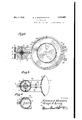
- Figure 1 is a vertical transverse section of a diagrammatic character
- Figure 2 is a horizontal cross-section taken on the line 22 of Figure 1;
- Figure 3 is a horizontal fragmentary crosssection taken on line 38 of Figure 1;
- Figure 4 is a horizontal fragmentary crosssection taken on line 4-4 of Figure 1.
- two chambers, 1 and 2 are provided which may be conveniently of cylindrical shape, chamher 1 of lesser diameter than chamber 2 and these chambers are associated by suitable frame work 30 and their interiors are in communication as by a tubular connection 22 positioned slightly below the vertical center.
- Chamber 1 is provided with an interior tubular member 3 having a. flaring or funnel top 32 positioned slightly below the top of chamber 1 and having its lower end open and centrally positioned within chamber 1 as by a frame member 31. Chamber 1 is covered by a top 7 provided with centrally positioned bearing 6 and with an outlet pipe 15 associated with a'valve 16' to provide the escape of gases from the chamber.
- a bearing 4 is mounted on the bottom of tubular member 3 and a vertical shaft 5 is journalled in bearings 4 and 6, said shaft 5 being provided with a plurality of stirring vanes 8 throughout the length of tubular member 3.
- An oil header 10 into which the crude oil is fed is connected with chamber 1 by inlet nozzles 11 adapted to direct the oil mixture against impact wheels 9 to rotate the same.
- a funnel 12 associated with an outlet pipe '13 controlled by valve 14 through which sediment deposited from the oil mixture within chamber 1 can be withdrawn at intervals.
- Ihamber 2 is provided at its bottom with a similar funnel member 23 associated with an outlet pipe 24 and valve 25 through which sediment deposited within chamber 2 may be withdrawn at intervals.
- a top 19 is provided for chamber 2, having a gas outlet 20 controlled by valve 21.
- Within chamber 2 and spaced slightly from the top thereof is an annular flange 16 defining an annular gutter 17.
- I Said annular gutter 17 communicates with an outlet overflow pipe 18.
- a glass depth gage 29 is mounted upon the side of chamber 2 to permit observation of the depth of the contents of the chamber.
- a vertical water stand pipe 27 communicates with chamber 2 adjacent its bottom as at 26 and is preferably associated with short length pipes 28 by means of which this vertical water stand pipe can be adjusted in length for the purpose of varying the hydrostatic head operating to control the level of oil, and the rate of flow of oil through the overflow pipe 18.
- the effective length of the stand pipe 27 can also be varied by rotating the pipe 27 about the short pipe 26 to raise orlower the water line level between the oil and water on chamber 2, in order to insure a gentle flow of oil over the top of flange 16 silid discharge thereof through overflow pipe
- the oil which is to be separated is fed into header 10 and thence through inlet nozzles 11 against impact wheels 9, thus rotating shaft 5 and stirrer blades 8.
- the oil mixture then passes downwardly through funnel mouth 32, through tubular member 3 and out at the bottom of said tubular member into chamber 1, in which the coarser sediment will precipitate into funnel 12.
- Apparatus iior continuously separating liquids of dilierent specific gravities from a mixture of such liquids comprising a settling tank in which liquids from said mixture settle in superposed layers and in accordance with their specific :gr-avi-ties, a frusto-conical cutting ring secured in said tank near the upper end thereof, a valve control sediment removing hopper at the bottom of said tank, fecdingsaid mixture into said tank between the ends thereof, means for dis charging the upper layer of liquid overflowing from the top of said cutting ring, a pipe connected to said tank to discharge liquids from the lower of-said layers, said pipe being adjustable to control the level of separation between said layers andtocontrol thereby the I rate of discharge of the upper layer of liquids through said discharging means.
- Apparatusforseparatingoil from water in a mixture of oil and water comprising an agitating chamber and a settling chamber arranged vertically and parallel to each other, means at the top of said agitating chamber for feeding said mixture to said agitating chamber, means for agitating said mixture in the vertical column thereof formed in said chamber, a valve controlled sediment remover at the bottomof said agitating chamher, a pipe for conducting the agitated mixture from the agitating ch-amber into the settling, chamber, a valve controlled sedi ment remover at the bottom of said settling chamber, a frusto-conical oil cutting ring near the top of said settling chamber,'a discharge outlet on said settling chamber to discharge oil'iiowing down the inclined side of said ring, a discharge pipe connected to said settling chamber near the lower end thereof to qonduct water from the water layer, said discharge pipe being adjustable to vary the hydrostatic head acting on the superposed layers to control the rate of discharge of oil from said chamber;
Landscapes
- Life Sciences & Earth Sciences (AREA)
- Engineering & Computer Science (AREA)
- Geology (AREA)
- Mining & Mineral Resources (AREA)
- Physics & Mathematics (AREA)
- Environmental & Geological Engineering (AREA)
- Fluid Mechanics (AREA)
- General Life Sciences & Earth Sciences (AREA)
- Geochemistry & Mineralogy (AREA)
- Physical Water Treatments (AREA)
Description
y 1932- E. A. SHOWERS ET AL 1,856,662
OIL SEPARATOR Filed Dec. 12, 1929 2 Sheets-Singet 1 Fig.1.
Jmwn m Edward fl. 5/10Wer5 andLZUHd Q. L g
y 3, 1932- E. A. SHOWERS ET AL 1,856,562
OTL S EPARATOR Filed Dec. 12, 1929 2 Sheets-Sheet 2 gwuentom a Edwardfl. 5/z0n/Er5 IhdLZZE/dfl- Lang Patented May 3, 1932 UNTED STATES PATENT @FFECE OIL SEPARATOR Application filed December 12, 1929. Serial No. 413,559.
This invention relates to a device for separating water and solid impurities from oil.
The object of the invention is to provide a simple and improved device by means of which crude oil can be readily and efficiently separated from water and solid impurities.
The invention consists in the new and improved construction, arrangements and combinations of parts hereinafter more particularly described and claimed.
In the drawings:
Figure 1 is a vertical transverse section of a diagrammatic character;
Figure 2 is a horizontal cross-section taken on the line 22 of Figure 1;
Figure 3 is a horizontal fragmentary crosssection taken on line 38 of Figure 1; and
Figure 4 is a horizontal fragmentary crosssection taken on line 4-4 of Figure 1.
In accordance with the drawings two chambers, 1 and 2, are provided which may be conveniently of cylindrical shape, chamher 1 of lesser diameter than chamber 2 and these chambers are associated by suitable frame work 30 and their interiors are in communication as by a tubular connection 22 positioned slightly below the vertical center.
A bearing 4 is mounted on the bottom of tubular member 3 and a vertical shaft 5 is journalled in bearings 4 and 6, said shaft 5 being provided with a plurality of stirring vanes 8 throughout the length of tubular member 3. Upon the upper end of shaft 5 and above the funnel mouth 32 of the tubular member 3 are mounted impact wheels 9. An oil header 10 into which the crude oil is fed is connected with chamber 1 by inlet nozzles 11 adapted to direct the oil mixture against impact wheels 9 to rotate the same.
In the bottom of chamber 1 is positioned a funnel 12 associated with an outlet pipe '13 controlled by valve 14 through which sediment deposited from the oil mixture within chamber 1 can be withdrawn at intervals.
Ihamber 2 is provided at its bottom with a similar funnel member 23 associated with an outlet pipe 24 and valve 25 through which sediment deposited within chamber 2 may be withdrawn at intervals. A top 19 is provided for chamber 2, having a gas outlet 20 controlled by valve 21. Within chamber 2 and spaced slightly from the top thereof is an annular flange 16 defining an annular gutter 17. I Said annular gutter 17 communicates with an outlet overflow pipe 18. A glass depth gage 29 is mounted upon the side of chamber 2 to permit observation of the depth of the contents of the chamber.
A vertical water stand pipe 27 communicates with chamber 2 adjacent its bottom as at 26 and is preferably associated with short length pipes 28 by means of which this vertical water stand pipe can be adjusted in length for the purpose of varying the hydrostatic head operating to control the level of oil, and the rate of flow of oil through the overflow pipe 18. The effective length of the stand pipe 27 can also be varied by rotating the pipe 27 about the short pipe 26 to raise orlower the water line level between the oil and water on chamber 2, in order to insure a gentle flow of oil over the top of flange 16 silid discharge thereof through overflow pipe In operation the oil which is to be separated is fed into header 10 and thence through inlet nozzles 11 against impact wheels 9, thus rotating shaft 5 and stirrer blades 8. The oil mixture then passes downwardly through funnel mouth 32, through tubular member 3 and out at the bottom of said tubular member into chamber 1, in which the coarser sediment will precipitate into funnel 12.
From chamber 1 the mixture largely water and oil will pass through tubular connection 22 into chamber 2, in which chamber the oil will rise to the top and the water settle to the bottom and in which chamber further precipitation of any remaining sediment will occur with the deposit of such sediment in tures.
means for the funnel 23. The water in the lower part of chamber 2 will rise in the water stand pipe 27 to create a head pressure sufficient to raise the oil in the upper part of chamber 2 to the level of the top of the outlet flange member 16, over which flange member the oil will gently overflow to be drawn iofl' through overflow pipe 18. e
Various modifications in the precise structure and arrangement of particular parts will readily suggest themselves to those skilled in the art but all within the scope of the present invention. 4
Having thus fully described our invention, we claim: p
1. Apparatus iior continuously separating liquids of dilierent specific gravities from a mixture of such liquids, comprising a settling tank in which liquids from said mixture settle in superposed layers and in accordance with their specific :gr-avi-ties, a frusto-conical cutting ring secured in said tank near the upper end thereof, a valve control sediment removing hopper at the bottom of said tank, fecdingsaid mixture into said tank between the ends thereof, means for dis charging the upper layer of liquid overflowing from the top of said cutting ring, a pipe connected to said tank to discharge liquids from the lower of-said layers, said pipe being adjustable to control the level of separation between said layers andtocontrol thereby the I rate of discharge of the upper layer of liquids through said discharging means.
2. Apparatusforseparatingoil from water in a mixture of oil and water, comprising an agitating chamber and a settling chamber arranged vertically and parallel to each other, means at the top of said agitating chamber for feeding said mixture to said agitating chamber, means for agitating said mixture in the vertical column thereof formed in said chamber, a valve controlled sediment remover at the bottomof said agitating chamher, a pipe for conducting the agitated mixture from the agitating ch-amber into the settling, chamber, a valve controlled sedi ment remover at the bottom of said settling chamber, a frusto-conical oil cutting ring near the top of said settling chamber,'a discharge outlet on said settling chamber to discharge oil'iiowing down the inclined side of said ring, a discharge pipe connected to said settling chamber near the lower end thereof to qonduct water from the water layer, said discharge pipe being adjustable to vary the hydrostatic head acting on the superposed layers to control the rate of discharge of oil from said chamber;
' In testimony whereof we aifix our signa- LLOYD A. LONG.
Priority Applications (1)
| Application Number | Priority Date | Filing Date | Title |
|---|---|---|---|
| US413559A US1856662A (en) | 1929-12-12 | 1929-12-12 | Oil separator |
Applications Claiming Priority (1)
| Application Number | Priority Date | Filing Date | Title |
|---|---|---|---|
| US413559A US1856662A (en) | 1929-12-12 | 1929-12-12 | Oil separator |
Publications (1)
| Publication Number | Publication Date |
|---|---|
| US1856662A true US1856662A (en) | 1932-05-03 |
Family
ID=23637697
Family Applications (1)
| Application Number | Title | Priority Date | Filing Date |
|---|---|---|---|
| US413559A Expired - Lifetime US1856662A (en) | 1929-12-12 | 1929-12-12 | Oil separator |
Country Status (1)
| Country | Link |
|---|---|
| US (1) | US1856662A (en) |
Cited By (5)
| Publication number | Priority date | Publication date | Assignee | Title |
|---|---|---|---|---|
| US2451882A (en) * | 1945-08-17 | 1948-10-19 | Walter C J Smith | Liquid proportioning gauge or indicator |
| US4039458A (en) * | 1974-11-08 | 1977-08-02 | Rhone-Poulenc Industries | Apparatus for separation by decantation |
| US4218311A (en) * | 1974-05-02 | 1980-08-19 | Davy International (Oil & Chemicals) Limited | Solvent extractor |
| US20100074568A1 (en) * | 2007-06-01 | 2010-03-25 | Ntn Corporation | Wheel Bearing Apparatus For A Vehicle |
| WO2018102436A3 (en) * | 2016-11-29 | 2019-12-12 | Galletta Robert J | Passive gravity filter cell and methods of use thereof |
-
1929
- 1929-12-12 US US413559A patent/US1856662A/en not_active Expired - Lifetime
Cited By (7)
| Publication number | Priority date | Publication date | Assignee | Title |
|---|---|---|---|---|
| US2451882A (en) * | 1945-08-17 | 1948-10-19 | Walter C J Smith | Liquid proportioning gauge or indicator |
| US4218311A (en) * | 1974-05-02 | 1980-08-19 | Davy International (Oil & Chemicals) Limited | Solvent extractor |
| US4039458A (en) * | 1974-11-08 | 1977-08-02 | Rhone-Poulenc Industries | Apparatus for separation by decantation |
| US20100074568A1 (en) * | 2007-06-01 | 2010-03-25 | Ntn Corporation | Wheel Bearing Apparatus For A Vehicle |
| WO2018102436A3 (en) * | 2016-11-29 | 2019-12-12 | Galletta Robert J | Passive gravity filter cell and methods of use thereof |
| IL266943B (en) * | 2016-11-29 | 2022-11-01 | Robert J Galletta | A passive gravity filter cell for silicon and methods for using it |
| IL266943B2 (en) * | 2016-11-29 | 2023-03-01 | Robert J Galletta | Passive gravity filter cell and methods of use thereof |
Similar Documents
| Publication | Publication Date | Title |
|---|---|---|
| US4406789A (en) | Apparatus and installation for separating immiscible liquids with different specific gravities | |
| US5407584A (en) | Water clarification method | |
| US3951816A (en) | Clarification tank | |
| US4043912A (en) | Clarification tank | |
| JP3331219B2 (en) | Method and apparatus for separating insoluble particles from a liquid | |
| US2307154A (en) | Apparatus for continuous clarification | |
| US2565343A (en) | Liquid separation | |
| US2418950A (en) | Settling tank | |
| US4218311A (en) | Solvent extractor | |
| US1135997A (en) | Apparatus for the separation of finely-divided solids from liquids. | |
| US1856662A (en) | Oil separator | |
| US3395800A (en) | Sewage treatment and apparatus therefor | |
| RU2135886C1 (en) | Method of device for preliminary disposal of water in gathering systems of oil production wells | |
| US2084958A (en) | Liquid separation method and apparatus | |
| US1574557A (en) | Filtering apparatus | |
| US1449603A (en) | Method of separating granular solid material | |
| US2169442A (en) | Thickener | |
| US4313826A (en) | Liquid-liquid extraction apparatus | |
| US1800965A (en) | Separation of liquids and solids | |
| US1662702A (en) | Begaoteb | |
| US1754870A (en) | Apparatus for the separation of finely-divided solids from liquids | |
| US1427446A (en) | Decantation apparatus | |
| US2821306A (en) | Pre-clarifier for separating solids and liquids | |
| US5779917A (en) | Process for separating fluids having different densities | |
| US1960686A (en) | Decanter |