US1856654A - Terminating circuit for two-way signaling systems - Google Patents
Terminating circuit for two-way signaling systems Download PDFInfo
- Publication number
- US1856654A US1856654A US517705A US51770531A US1856654A US 1856654 A US1856654 A US 1856654A US 517705 A US517705 A US 517705A US 51770531 A US51770531 A US 51770531A US 1856654 A US1856654 A US 1856654A
- Authority
- US
- United States
- Prior art keywords
- circuit
- receiving
- cable
- amplifier
- transmitting
- Prior art date
- Legal status (The legal status is an assumption and is not a legal conclusion. Google has not performed a legal analysis and makes no representation as to the accuracy of the status listed.)
- Expired - Lifetime
Links
- 230000011664 signaling Effects 0.000 title description 4
- 239000004020 conductor Substances 0.000 description 28
- 238000004804 winding Methods 0.000 description 21
- 230000005540 biological transmission Effects 0.000 description 7
- 239000002131 composite material Substances 0.000 description 4
- 230000008878 coupling Effects 0.000 description 4
- 238000010168 coupling process Methods 0.000 description 4
- 238000005859 coupling reaction Methods 0.000 description 4
- 230000000694 effects Effects 0.000 description 3
- 206010019133 Hangover Diseases 0.000 description 2
- 230000008901 benefit Effects 0.000 description 2
- 230000007246 mechanism Effects 0.000 description 2
- 230000004048 modification Effects 0.000 description 2
- 238000012986 modification Methods 0.000 description 2
- 235000014748 Amaranthus tricolor Nutrition 0.000 description 1
- 244000024893 Amaranthus tricolor Species 0.000 description 1
- 208000007256 Nevus Diseases 0.000 description 1
- 235000010725 Vigna aconitifolia Nutrition 0.000 description 1
- 238000005513 bias potential Methods 0.000 description 1
- 238000010586 diagram Methods 0.000 description 1
- 230000004907 flux Effects 0.000 description 1
- 230000000266 injurious effect Effects 0.000 description 1
- 238000009877 rendering Methods 0.000 description 1
- 239000004576 sand Substances 0.000 description 1
- 230000003068 static effect Effects 0.000 description 1
Images

Classifications
-
- H—ELECTRICITY
- H04—ELECTRIC COMMUNICATION TECHNIQUE
- H04B—TRANSMISSION
- H04B3/00—Line transmission systems
- H04B3/02—Details
- H04B3/20—Reducing echo effects or singing; Opening or closing transmitting path; Conditioning for transmission in one direction or the other
Definitions
- the present invention relates to a terminating circuit for a two-way signaling system using a ground return such, for eXample, as in the case of a transoceanic telephone
- a terminating circuit for a two-way signaling system using a ground return such, for eXample, as in the case of a transoceanic telephone
- Two-way transmission over a cable is obtained by switching the cable into and out of connection with a transmitting branch and a receiving branch alternatively to enable the transmit or to receive.
- the switch mechanisms for accomplishing this are controlled by the speech waves or other current traversing the system. ln the usual ycase of a long cable having high attenuation the transmitting energy is enormous in cornparison with the received energy.
- the present invention meets these various requirements and also provides an eiiicient and properly proportioned terminal circuit for accomplishing two-way speech transmis sion between land line circuits and a transoceanic telephone cable.
- the invention has several important advantages and features which will appear more fully from the detailed specification and description to follow.
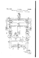
- Fig. 1 shows a schematic circuit diagram of a terminating circuit for a transoceanic cable
- Figs. 2 and 3 show detail modications of a part of the circuit of Fig. 1.
- the land line LL at the left is arranged for twoway repeating with the deep sea cable GL shown at the right in the ligure, through the medium of a four-wire circuit comprising a transmitting branch T and a receiving branch R.
- a four-wire land line L1, L2 may be substituted for the line LL, Ll being for transmitting and L2 for receiving.
- Resistance pads 53 and 54 prevent singing due to unbalance when the twoway line LL is used.
- the cable itself comprises the usual sheath 1, the cable core, indicated at :2, and two other conductors 3 and 4, leading respectively to a sending sea earth which may be a fraction of a mile from shore, to a receiving sea earth which may be several miles out for the purpose of reducing interference such as static noise.
- the earth connections for the conductors 3 and 4 are made by attaching these conductors electrically to the cable sheath.
- the receiving sea earth conductor4 includes an impedance 5 equal to the characteristic impeoance of the cable itself.
- Two transformers 6 and 7, which may be identically alilre, are provided for connecting the cable 'respectively to the 'transmitting and receiving branches of the four-wire cirof the large capacity cuit.
- the transformer 6 has one winding 8 connected'between conductor 3 anda terminal 10 the opposite terminal of which is directly connected to theY cable core 2.V
- the transformer 7 has a winding 9 connected between receiving sea earth 4 in series with the large capacityV 11 and to 'the same terminal-of the capacity 10 that the winding Sis connected to.
- the other winding 12 of transformer 6 is connectedthrough switching points to the secondarywinding ofthe output transformer 13 in the transmitting branch T.
- the other winding 15 of transformer 7 is connected through switching points and through equalizer 16 to the primary winding of the receiving or input transformer 17 in the receiving branch R.
- the transmitting branch T also contains, inaddition to the lelements already named, avariable amplifier serving as a volume control 20, an equalizer 22 ⁇ and a power amplifier 23which may contain any desired number of stages. Branched od from the transmitting circuit T between the volume control 2O and equalzer'22 is a circuit leading to the amplier detector 2l for controlling the switching operation,vthis amplified detector being identical. with that disclosed in my prior application referred to. y
- the receiving branch R contains in addition to the elements already mentioned and beginning at the secondary of transformer 17, a receiving amplifier-24, equalizer 25, and further amplifiers 26 and 27, the latter of which is 'shown to be'variable for volume control purposes.
- 'Between amplifiers 26 and 27 a circuit is branched off from the receiving circuit R leading to ampliiier detector 63 which may be identical with the corresponding amplifier detector of my prio*1 application referred to.
- this amplifier detector 63 instead of acting precisely as disclosed in my prior application, controls actuation of a relay 31 which when its armature isattracted opens the input circuit of the amplifier detector 21 to insure the latter against false operation during receiv-I ,ingk periods.
- transmitting circuit T isA normally in Ya disabled condition and tl receiving circuit R is normally operative to receive-signals from the cable.
- the speech wavesreceived from-the cable are transferred ceived.
- the waves which are received over the line LL pass into the volume control 20 and from there into equalizer 22 and ampliiier 23.
- amplifier 23 is inoperative to transmit as disclosed in my prior application, due to the fact that an abnormally large negative grid bias is applied over ⁇ l wire from the output of amplifier detector 21.
- the transmitting circuit T is also disabled at a further point by the armatures of relays y41 and 42, the former of which normally holds open the series circuit between transformers 13 and 6 and normally holds closed a shunt across the secondary windir of transformer 13.
- Relay 42 is a transf-er relay for lalternately connecting the common grounded side of branches Tand R to the windings 12 and 15 respectively. lt may be omitted if desired, and only the relays 4() and 41 used.
- the speech waves bein gk transmitted pass in part into ampliiier detector 21 and setup such a voltage therein, as describirj in my prior applicatiomthat the grid potential of amplifier 23 is shi ted to its proper value for transmitting purposes, this voltage being applied between conductor 30 and the ground conductor leading to the filament of the amplifier.
- Relay 34 attracts its armature thus removing the normal shunt which has up to this time existed across the terminals of battery 38 and resistance 39.
- Relays 40, 41 and 42 therefore attract their armatures.
- Relay in attracting its armature opens at the back contact of the armature the receiving circuit lower conductor between secondary 15 of trans-former 7 and-the input to equalizer 16. When the armature completes'its stroke it closes at its front contact a shunt across the input to the equalizerk 16.
- Relay 41 in attracting its armature first opens the normal shunt across the transmitting circuit, and/at the completion of the armature stroke, closes the upper conductor of the secondary of transformer 13 through to the primary 12 of the coupling transformer 6.
- Transfer relay 42 opens the ground side of the receiving branch from transformer 7 and closes that. of the sending branch.
- amplifier detect-or 21 placed a potential on the grid of the amplifier stage E23 through conductor 30, it also aph lied over conductor 50 a large negative grid ias 'potential to the grid terminal of amplifier 26 in the manner disclosed more fully in my prior application referred to, so that during the transmitting period amplifier Q6 is rendered incapable of transmitting by virtue of the excessive negative bias potential on the grid.
- amplifier 26 may comprise a number of stages.
- Relay in releasing its armature first opens the short circuit that has been placed across the receiving circuit during the time transmission has been going on and at its back Contact establishes a normal connection for the receiving circuit including the secondary winding 15 of transformer 7 and the input leads to the equalizer 16.
- Relay 42 in releasing further opens the transmitting branch and closes the receiving branch.
- these coupling transformers 6 and 7 also makes it possible to insulate the cable proper from the station equipment so as to provide maximum protection from accidental application of the station batteries directly to the cable.
- These transformers are suitably shielded for purposes of protection and also for the purpose of draining off any unbalanced currents which may exist.
- the receiving circuit has one side always connected to ground, the switching point being connected so as not to open or close this circuit connection.
- T ie equalizer 16 may be of the balanced or unbalanced type.
- relay 41 may be omitted, and relay 42 alone be depended on to open the sending branch.
- Condensers have been shown in series with the main core and the receiving earth to miniinize the effect of earth currents .and these condensers will also serve to reduce the interference from telegraph in case the cable is composited.
- Telephone composite sets have been indicated in Fig. 1 and such sets may be connected either between the main core and the sending earth or the main core and the receiving earth without the introduction of unbalances.
- the telegraph composite set 45 may comprise any suitable telegraph terminal apparatus, either printer or other type, and may have provision foreither sending or receiving. This connected through filter 46 either to the terminals 47 or to the terminals 48 depending upon whether it is to be connected between the cable core and the sending ground or the cable core and the receiving ground.
- the relay 41 of Fig. 1 is omitted betweenthe transformers 13 and 6 and the. switching in the transmitting side is carried out in the output of transformer 6 byproviding relay al as shown in Fig. 2.
- the energizing circuit forrelays alf and-l2 may be identical with that for the corresponding re,- lays of Fig,V i.
- the switching point as shown in Fig. 2 instead ef at the Vplace .shown at l ig. l, the shunt circuit from the cable core through winding 8 of Fig. lY to ground is open during receiving since relay al of Fig. 2 entirely cuts olf the transmitting circuit during the receiving period.
- a four-wire terminating circuit for a transmission line comprising two electricallyA similar transformers each having one winding adapted for connection to said line and another winding adapted for connection respectively to a transmitting branch and a receiving branch of said four-wire circuit, a sending amplifier in the transmitting branch and a step-down transformer connected between said amplifier and one of said two .lier in the receiving branch and a step-up transformer between thesecond of said two similar transformers andsaid receiving ampliiier, and voice-operated circuit means associated with said branches for alternately rendering them respectively ⁇ operative and g non-operative.
- a circuit according to claimv l in ywhich said 'transmission line is a -transoceanic vcable having a core, a receiving sea earth and a sending earth, one of said two similar transformers ⁇ being adapted for connection between the core and the receiving sea earth and the other between the cor-sand thesending earth.
- said voice-operated circuit means includes a disabling means in the transmitting branch at a point between the two mentioned transformers therein and another disabling means in the receiving 'branch ata point between the twci mentioned transformers therein.
- said voice-operated circuit means includes a disabling means located between the trans'- mission line and the winding ofthe transform'eradapted kfor connection to-said line,
- a four-Wire terminating circuit for a Vcable having a core and a receiving' sea earth conductor and a sending earth conductor, separate andelectrically similar trans yformers coupling' said cablerespectively to the transmittingY and receiving branches of said four-wirev circuit, and series capacities between the core and the lead to. said transformers and between the receiving sea earth conductor andthe lead to said transformer inthe receiving branch.
- the combination Vaccording to claim 5 including also a telegraph composite apparatus connected between a point on said core and kone of said other conductors, the cirwhose other winding' is Vconnected to said ⁇ cuit between said .composite apparatus and .said core and other mentioned conductor eX- vclud-ing .said vseries capacities.
- ln a deep sea telephone cable system, a cable having a core and a sending earth conductor, aspeech transformer having a winding connected between said lcore and conductor, yand large series capacity in the circuit of said winding.
- a deep sea telephonecable system a Vcable having a core and a receiving sea earth conductor, a speech transformer having a winding connected betweensaid core and conductor, and large series capacity in the circuit of said winding.
Landscapes
- Engineering & Computer Science (AREA)
- Computer Networks & Wireless Communication (AREA)
- Signal Processing (AREA)
- Cable Transmission Systems, Equalization Of Radio And Reduction Of Echo (AREA)
Description
May: 3, 1932. c. N. NEBEL 1,855,654
' TERMINATING CIRCUIT FOR TWO-WAY SIGNALING SYSTEMS Filed Feb. 24, 1931 2 Sheets-Sheet l A T T'URNE May 3, 1932- c. N. NEBEL 1,856,654I
TERMINATING CIRCUIT FOR TWO-WAY SIGNALING SYSTEMS Filed Feb. 24, 1931- 2 Sheets-Sheet 2 I M /NVE/vroR ,u I Y CMA/EBEL wie* 4 TTD/PNE? cable.
system either to Patented May 3, 1932 NETE@ STATES ATNT OFFC CEARLES N. NEBEL, OF NEWARK, NEW JERSEY, .ASSIGNOR T0 BELL TELEPHONE LAB- ORATORIESINC'ORPGRATED, OE NEVI YORK, N.
Y., i CORPORATON OF NEW YORK TERMIINATING CRCUIT FOR TW'G-'VIAY SGNALING SYSTEMS Application filed February 24, 1931. Serial No. 517,705.
The present invention relates to a terminating circuit for a two-way signaling system using a ground return such, for eXample, as in the case of a transoceanic telephone Two-way transmission over a cable is obtained by switching the cable into and out of connection with a transmitting branch and a receiving branch alternatively to enable the transmit or to receive. The switch mechanisms for accomplishing this are controlled by the speech waves or other current traversing the system. ln the usual ycase of a long cable having high attenuation the transmitting energy is enormous in cornparison with the received energy. rFhis fact malres it important to insure that no connection is ever made between the transmitting branch and the receiving branch such as rwould result in impressing on the receiving branch a large amount of energy, which might destroy the relatively sensitive receiving apparatus or produce other troublesome or disturbing effects in the receiving circuit.
- 1n providing the necessary switching mechanism, it is important that no si 7itch contacts' be used in the cable or ground conductors themselves since otherwise clicks of large magnitude may be produced in the receiving circuit due to the very considerable differences of potential that exist between different portions of the circuit. lt is also important to insulate the cable proper from the station equipment so as to provide against accidental application of the high voltages used in transmitting directly to the cable.
The present invention meets these various requirements and also provides an eiiicient and properly proportioned terminal circuit for accomplishing two-way speech transmis sion between land line circuits and a transoceanic telephone cable. The invention has several important advantages and features which will appear more fully from the detailed specification and description to follow.
In the drawings Fig. 1 shows a schematic circuit diagram of a terminating circuit for a transoceanic cable; and
Figs. 2 and 3 show detail modications of a part of the circuit of Fig. 1.
My prior application for Letters Patent, Serial No. 459,663, filed June 7, 1930, discloses a two-way terminal circuit for a transoceanic cable of the so-called twin-core type in which the cable is connected to the terminal circuit through a single two-winding transformer. In the present application the type of transoceanic cable that is disclosed is of the single core type comprising a core, a sending sea earth and a separate receiving sea earth, and the invention has particular reference to a terminating circuit for 'this type of cable. Except for this main dierence the general transmitting and receiving circuit elements and the voice operated switching elements may be similar to those disclosed in my prior application referred to. Since these particular elements in detail form no part of the present invention they will not be described specifically but the nature of their function and operation will be clear from my prior application to which reference may be made. The drawings have been simplified to omit the details of these various elements but the elements are generally indicated in the drawings by similar reference characters to those employed in my prior application.
Referring now to Fig. 1 of the drawings, the land line LL at the left is arranged for twoway repeating with the deep sea cable GL shown at the right in the ligure, through the medium of a four-wire circuit comprising a transmitting branch T and a receiving branch R. By throwing the switches 49 and 51 to their alternate positions, a four-wire land line L1, L2 may be substituted for the line LL, Ll being for transmitting and L2 for receiving. Resistance pads 53 and 54 prevent singing due to unbalance when the twoway line LL is used.
The cable itself comprises the usual sheath 1, the cable core, indicated at :2, and two other conductors 3 and 4, leading respectively to a sending sea earth which may be a fraction of a mile from shore, to a receiving sea earth which may be several miles out for the purpose of reducing interference such as static noise. The earth connections for the conductors 3 and 4 are made by attaching these conductors electrically to the cable sheath. The receiving sea earth conductor4 includes an impedance 5 equal to the characteristic impeoance of the cable itself.
Two transformers 6 and 7, which may be identically alilre, are provided for connecting the cable 'respectively to the 'transmitting and receiving branches of the four-wire cirof the large capacity cuit. The transformer 6 has one winding 8 connected'between conductor 3 anda terminal 10 the opposite terminal of which is directly connected to theY cable core 2.V The transformer 7 has a winding 9 connected between receiving sea earth 4 in series with the large capacityV 11 and to 'the same terminal-of the capacity 10 that the winding Sis connected to. The other winding 12 of transformer 6 is connectedthrough switching points to the secondarywinding ofthe output transformer 13 in the transmitting branch T. The other winding 15 of transformer 7 is connected through switching points and through equalizer 16 to the primary winding of the receiving or input transformer 17 in the receiving branch R.
. The transmitting branch T also contains, inaddition to the lelements already named, avariable amplifier serving as a volume control 20, an equalizer 22`and a power amplifier 23which may contain any desired number of stages. Branched od from the transmitting circuit T between the volume control 2O and equalzer'22 is a circuit leading to the amplier detector 2l for controlling the switching operation,vthis amplified detector being identical. with that disclosed in my prior application referred to. y
.The receiving branch R contains in addition to the elements already mentioned and beginning at the secondary of transformer 17, a receiving amplifier-24, equalizer 25, and further amplifiers 26 and 27, the latter of which is 'shown to be'variable for volume control purposes. 'Between amplifiers 26 and 27 a circuit is branched off from the receiving circuit R leading to ampliiier detector 63 which may be identical with the corresponding amplifier detector of my prio*1 application referred to. For simplicity of showing, this amplifier detector 63 instead of acting precisely as disclosed in my prior application, controls actuation of a relay 31 which when its armature isattracted opens the input circuit of the amplifier detector 21 to insure the latter against false operation during receiv-I ,ingk periods.
-As described more fully in kmy prior application referred to the transmitting circuit T isA normally in Ya disabled condition and tl receiving circuit R is normally operative to receive-signals from the cable. The speech wavesreceived from-the cable are transferred ceived.
by transformer 7 through the normally closed back Contact of relays 40 and 42, equalizer 16 to the primary of the step-up transformer 17, the secondary of which is connected directly to the receiving amplifier 24.A Further YKequalization takes place in equalizer and the waves are further amplilied by amplifiers 26 and 27 and impressed upon the land line LL. The speech waves in the output of amplitier 26 act through amplifier detector 63 to operate relay 31 thus kdisabling amplifier 21 during the time when speech is being re- Equalizers 16 and 25 may be designed in accordance with the disclosure of the U. S. Patent No. 1,844,422, to Mathes and lr-iorton. Infgeneral, they have a loss characteristic which is very much greater for the lower speech frequencies than for the high in order to compensate for distortion in thecable and to provide for any so-called reshaping of the waves that may be necessary.
During the transmitting period and in the absence of speech waves in the receiving circuit R, the waves which are received over the line LL, pass into the volume control 20 and from there into equalizer 22 and ampliiier 23. At this time, however, amplifier 23 is inoperative to transmit as disclosed in my prior application, due to the fact that an abnormally large negative grid bias is applied over` l wire from the output of amplifier detector 21. The transmitting circuit T is also disabled at a further point by the armatures of relays y41 and 42, the former of which normally holds open the series circuit between transformers 13 and 6 and normally holds closed a shunt across the secondary windir of transformer 13. Relay 42 is a transf-er relay for lalternately connecting the common grounded side of branches Tand R to the windings 12 and 15 respectively. lt may be omitted if desired, and only the relays 4() and 41 used. The speech waves bein gk transmitted pass in part into ampliiier detector 21 and setup such a voltage therein, as describirj in my prior applicatiomthat the grid potential of amplifier 23 is shi ted to its proper value for transmitting purposes, this voltage being applied between conductor 30 and the ground conductor leading to the filament of the amplifier.
As a result of this shift in the grid potential of amplifier 23 space current flows through the ampliiier tube and through the winding of relay 34 from the plate batterj-,fy 33. Relay 34 attracts its armature thus removing the normal shunt which has up to this time existed across the terminals of battery 38 and resistance 39. Relays 40, 41 and 42 therefore attract their armatures. Relay in attracting its armature opens at the back contact of the armature the receiving circuit lower conductor between secondary 15 of trans-former 7 and-the input to equalizer 16. When the armature completes'its stroke it closes at its front contact a shunt across the input to the equalizerk 16. Relay 41 in attracting its armature first opens the normal shunt across the transmitting circuit, and/at the completion of the armature stroke, closes the upper conductor of the secondary of transformer 13 through to the primary 12 of the coupling transformer 6. Transfer relay 42 opens the ground side of the receiving branch from transformer 7 and closes that. of the sending branch.
At the same time that amplifier detect-or 21 placed a potential on the grid of the amplifier stage E23 through conductor 30, it also aph lied over conductor 50 a large negative grid ias 'potential to the grid terminal of amplifier 26 in the manner disclosed more fully in my prior application referred to, so that during the transmitting period amplifier Q6 is rendered incapable of transmitting by virtue of the excessive negative bias potential on the grid. As in the case of my prior application referred to this amplifier 26 may comprise a number of stages.
At the cessation of speech currents coming over the landline LL amplifier detector 21 is without current and the circuits restore to their normal condition after sufficient hangover time to insure that the last portions of the speech are transmitted. The potential applied over conductor 30 from amplifier detector 21 to grid of amplifier 23 shifts to high negative value reducing the space current to zero. Relay 34 then, after sufficient hangover, releases and causes relays 40, 41 and 42 to be deenergized. Relay 41 in releasing its armature opens the series transmission circuit between transformers 13 and 6 and at its baclr contact closes the normal short circuit across this path. Relay in releasing its armature first opens the short circuit that has been placed across the receiving circuit during the time transmission has been going on and at its back Contact establishes a normal connection for the receiving circuit including the secondary winding 15 of transformer 7 and the input leads to the equalizer 16. Relay 42 in releasing further opens the transmitting branch and closes the receiving branch.
At the time the speech waves ceased in the amplifier detector 21 the high negative potential that had been applied over conductor to the grids of the amplifier tube 26 was removed from conductor 5() so that amplifier 26 is restored to receiving condition.
llt will be noted that in the circuit of Fig. 1 no switching contacts are inserted in the cable conductors themselves either in the core or in the sending and receiving ground conductors. As stated above, there may be a considerable difference of potential between these three conductors and if switching contacts are inserted directly in these conductors,
clicks of large magnitude may be produced.
These are avoided, however, by placing the switching contacts at the positions shown on the drawings separated from the cable conductors by the coupling transformers 6 and 7.
The use of these coupling transformers 6 and 7 also makes it possible to insulate the cable proper from the station equipment so as to provide maximum protection from accidental application of the station batteries directly to the cable. These transformers are suitably shielded for purposes of protection and also for the purpose of draining off any unbalanced currents which may exist. lt will also be noted that the receiving circuit has one side always connected to ground, the switching point being connected so as not to open or close this circuit connection. T ie equalizer 16 may be of the balanced or unbalanced type.
lf desired, relay 41 may be omitted, and relay 42 alone be depended on to open the sending branch.
In the circuit of' Fig. 1 in the transmitting condition the impedance of the receiving earth in series with the primary vinding 9 of transformer 7 is bridged from the main cable core to ground and correspondingly, in receiving, the impedance of the oircuit transmitting winding 8 is bridged to groun d from the main core of the cable. This fact requires that 'the impedance of both of these windings be sufliciently high at all frequencies in the speech range to avoid an appreciable transmission loss and that these coils be constructed to cause no trouble from modulation. This latter effect can be realized by a substantially straight line characteristic between impressed voltages and flux in the cores of the transformers 6 and 7 which is attained by proper design of these transformers as is known in the art.
Condensers have been shown in series with the main core and the receiving earth to miniinize the effect of earth currents .and these condensers will also serve to reduce the interference from telegraph in case the cable is composited. Telegraph composite sets have been indicated in Fig. 1 and such sets may be connected either between the main core and the sending earth or the main core and the receiving earth without the introduction of unbalances. The telegraph composite set 45 may comprise any suitable telegraph terminal apparatus, either printer or other type, and may have provision foreither sending or receiving. This connected through filter 46 either to the terminals 47 or to the terminals 48 depending upon whether it is to be connected between the cable core and the sending ground or the cable core and the receiving ground.
lln the circuit modification disclosed in Fig. 2 the relay 41 of Fig. 1 is omitted betweenthe transformers 13 and 6 and the. switching in the transmitting side is carried out in the output of transformer 6 byproviding relay al as shown in Fig. 2. .The energizing circuit forrelays alf and-l2 may be identical with that for the corresponding re,- lays of Fig,V i. By providingthe switching point as shown in Fig. 2 instead ef at the Vplace .shown at l ig. l, the shunt circuit from the cable core through winding 8 of Fig. lY to ground is open during receiving since relay al of Fig. 2 entirely cuts olf the transmitting circuit during the receiving period.
ln the circuit modification shown in Fig. 3, the functions of relays 4:0 and al. of Fig. l .are combined in the one relay 5l to the eX- tent that thisrelay places a shunt across the transmitting or the receiving branch according as the `relay is deenergized or energized. Relay l2 is transfer relay serving to open or close the transmitting and receiving branches. rThese two relays are controlled by relay 3a as in Fig. l. An advantage of this circuit is that failure of either relay to yoperate when it should, as by sticking of armature, cannot result in applying excessive and injurious amounts of energy from the transmitter to the receiver branch.
What is claimed is: Y e v l. A four-wire terminating circuit for a transmission line, comprising two electricallyA similar transformers each having one winding adapted for connection to said line and another winding adapted for connection respectively to a transmitting branch and a receiving branch of said four-wire circuit, a sending amplifier in the transmitting branch and a step-down transformer connected between said amplifier and one of said two .lier in the receiving branch and a step-up transformer between thesecond of said two similar transformers andsaid receiving ampliiier, and voice-operated circuit means associated with said branches for alternately rendering them respectively `operative and g non-operative.
` 2. A circuit according to claimv l, in ywhich said 'transmission line is a -transoceanic vcable having a core, a receiving sea earth and a sending earth, one of said two similar transformers `being adapted for connection between the core and the receiving sea earth and the other between the cor-sand thesending earth.
8. A circuit according to claim l, in which said voice-operated circuit means includes a disabling means in the transmitting branch at a point between the two mentioned transformers therein and another disabling means in the receiving 'branch ata point between the twci mentioned transformers therein.
4. A circuit according to claim l, in which said voice-operated circuit means includes a disabling means located between the trans'- mission line and the winding ofthe transform'eradapted kfor connection to-said line,
similartransformers, a receiving amplitransmitting branch. y
r5. In a four-Wire terminating circuit for a Vcable having a core and a receiving' sea earth conductor and a sending earth conductor, separate andelectrically similar trans yformers coupling' said cablerespectively to the transmittingY and receiving branches of said four-wirev circuit, and series capacities between the core and the lead to. said transformers and between the receiving sea earth conductor andthe lead to said transformer inthe receiving branch. y
.6. The combination Vaccording to claim 5 including also a telegraph composite apparatus connected between a point on said core and kone of said other conductors, the cirwhose other winding' is Vconnected to said `cuit between said .composite apparatus and .said core and other mentioned conductor eX- vclud-ing .said vseries capacities.
. 7. ln a deep sea telephone cable system, a cable having a core and a sending earth conductor, aspeech transformer having a winding connected between said lcore and conductor, yand large series capacity in the circuit of said winding.
8. ln a deep sea telephonecable system, a Vcable having a core and a receiving sea earth conductor, a speech transformer having a winding connected betweensaid core and conductor, and large series capacity in the circuit of said winding. n Y
ln witness whereof, l hereunto subscribe my name this 20th day of February, 1931.
l CHARLES N. .NEBEL.
lli
Priority Applications (2)
| Application Number | Priority Date | Filing Date | Title |
|---|---|---|---|
| US517705A US1856654A (en) | 1931-02-24 | 1931-02-24 | Terminating circuit for two-way signaling systems |
| GB3369/32A GB396443A (en) | 1931-02-24 | 1932-02-04 | Improvements in or relating to terminating circuits for two-way electrical signalling systems |
Applications Claiming Priority (1)
| Application Number | Priority Date | Filing Date | Title |
|---|---|---|---|
| US517705A US1856654A (en) | 1931-02-24 | 1931-02-24 | Terminating circuit for two-way signaling systems |
Publications (1)
| Publication Number | Publication Date |
|---|---|
| US1856654A true US1856654A (en) | 1932-05-03 |
Family
ID=24060889
Family Applications (1)
| Application Number | Title | Priority Date | Filing Date |
|---|---|---|---|
| US517705A Expired - Lifetime US1856654A (en) | 1931-02-24 | 1931-02-24 | Terminating circuit for two-way signaling systems |
Country Status (2)
| Country | Link |
|---|---|
| US (1) | US1856654A (en) |
| GB (1) | GB396443A (en) |
-
1931
- 1931-02-24 US US517705A patent/US1856654A/en not_active Expired - Lifetime
-
1932
- 1932-02-04 GB GB3369/32A patent/GB396443A/en not_active Expired
Also Published As
| Publication number | Publication date |
|---|---|
| GB396443A (en) | 1933-08-04 |
Similar Documents
| Publication | Publication Date | Title |
|---|---|---|
| US2018464A (en) | Voice operated transmission circuit | |
| US2273945A (en) | Two-way speech transmission | |
| US1856654A (en) | Terminating circuit for two-way signaling systems | |
| US1865165A (en) | Transmission control circuits | |
| US2990457A (en) | Tandem echo suppressor circuits | |
| Wright et al. | The New York‐London Telephone Circuit | |
| US2061555A (en) | Transmission control in two-way signaling systems | |
| US1910165A (en) | Deep sea cable terminal | |
| US1953487A (en) | Transmission control circuits | |
| US1812624A (en) | Telephone and telegraph signaling system | |
| US1837316A (en) | Voice operated control arrangement for telephone cable systems | |
| US2258966A (en) | Control of transmission in two-way signaling systems | |
| US2054906A (en) | Transmission control in signaling systems | |
| US2491263A (en) | Ringing system for voice current repeaters | |
| GB397551A (en) | Improvements in electrical impedance networks and amplifiers | |
| US2047729A (en) | Transmission control in two-way signaling systems | |
| US2026305A (en) | Transmission control in signaling systems | |
| US2306689A (en) | Voice-operated switching circuit for two-way telephony | |
| US1953496A (en) | Long distance telephone system | |
| US1536907A (en) | Carrier-current system | |
| US1990414A (en) | Circuit for controlling transmission in signaling systems | |
| US2319717A (en) | Transmission control in two-way signal wave transmission systems | |
| US1850593A (en) | Transmission control | |
| US2083645A (en) | Transmission system | |
| US1639773A (en) | Two-way telephone transmission |