US1856652A - Spring plate holder for railroad road bed construction - Google Patents
Spring plate holder for railroad road bed construction Download PDFInfo
- Publication number
- US1856652A US1856652A US530378A US53037831A US1856652A US 1856652 A US1856652 A US 1856652A US 530378 A US530378 A US 530378A US 53037831 A US53037831 A US 53037831A US 1856652 A US1856652 A US 1856652A
- Authority
- US
- United States
- Prior art keywords
- plate
- tie
- rail
- spring
- spring plate
- Prior art date
- Legal status (The legal status is an assumption and is not a legal conclusion. Google has not performed a legal analysis and makes no representation as to the accuracy of the status listed.)
- Expired - Lifetime
Links
- 238000010276 construction Methods 0.000 title description 11
- 238000006073 displacement reaction Methods 0.000 description 4
- 230000000694 effects Effects 0.000 description 4
- 230000015572 biosynthetic process Effects 0.000 description 3
- 239000000463 material Substances 0.000 description 3
- 230000002452 interceptive effect Effects 0.000 description 2
- 238000010009 beating Methods 0.000 description 1
- 238000005452 bending Methods 0.000 description 1
- 230000007812 deficiency Effects 0.000 description 1
- 230000000994 depressogenic effect Effects 0.000 description 1
- 230000001788 irregular Effects 0.000 description 1
- 238000012423 maintenance Methods 0.000 description 1
- 230000000750 progressive effect Effects 0.000 description 1
- 230000000135 prohibitive effect Effects 0.000 description 1
- 230000008439 repair process Effects 0.000 description 1
- 239000011435 rock Substances 0.000 description 1
- 238000000926 separation method Methods 0.000 description 1
- 238000006467 substitution reaction Methods 0.000 description 1
Images

Classifications
-
- E—FIXED CONSTRUCTIONS
- E01—CONSTRUCTION OF ROADS, RAILWAYS, OR BRIDGES
- E01B—PERMANENT WAY; PERMANENT-WAY TOOLS; MACHINES FOR MAKING RAILWAYS OF ALL KINDS
- E01B9/00—Fastening rails on sleepers, or the like
- E01B9/02—Fastening rails, tie-plates, or chairs directly on sleepers or foundations; Means therefor
- E01B9/28—Fastening on wooden or concrete sleepers or on masonry with clamp members
- E01B9/30—Fastening on wooden or concrete sleepers or on masonry with clamp members by resilient steel clips
- E01B9/306—Fastening on wooden or concrete sleepers or on masonry with clamp members by resilient steel clips the clip being a shaped plate
Definitions
- the ties are thus subjected'to a continued pounding, obviously tending to a material disturbance of roadbed level, undue wear of the ties, and such loosening of the rail connections as to permit ready creeping of the rails, and not infrequently their lateral movement out of gauge.
- the primary object of the present invention is, therefore, the provision of means, in the form of a spring plate, which may, without change in the conventional units and substantially as a substitute for the usual holding spike, be used to securely hold the track units together under usual strains and stresses, while at the same time permitting the necessary track flexibility.
- a further object is the provision of a spring plate to be removably though securely held to the tie, with positive though yielding resistance to track movement, and the mounting of the plate to utilize the track movement to compel a lever action of the spring plate to increase the holdingpressure on the tie or tie plate, thus preventing play of such tie or tie plate and compelling the rail element to resume its natural position on the tie or tie plate without permitting relative movement of a nature resulting in permanent looseness.
- a further object is the provision of a spring plate designed to be secured by a member threaded into the tie, either directly or through the tie plate, with such plate having a part overlying the rail base, and a part overlying the tie or tie plate.
- Both bearing parts of the spring plate are of inherent spring construction, while the mounting of the spring plate relative to the threaded member provides for a leverage action under movement of the track incident to train load and travel, with the effect to exert an in creased holding effect on the tie or tie and tie plate.
- a further object is the provision of a spring plate which normally binds the rail and rail supporting elements as a unit, without interfering with that track movement necessarily preceding or following train load and travel, and which, while increasingly resisting such track movement, utilizes such movement to increase the holding efiect ofithe spring plate on the tie or tie and tie plate, and which in ment, utilizes such spring resistance to insure I that the rail and rail supports shall be held against longitudinal or lateral separation,
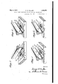
- Fig. 1 is a broken perspective view; illustrating the use of a form of the improved spring plate with atrack construction involving the use of a tie plate.
- ig. 2 is a similar view, the tie plate being omitted and the track being shown as directly secured to the tie, the spring plate shown being of the form of that shown in Fig. 1.
- Fig. 3' is a broken perspective view of a track mounting, illustrating a modified form of spring plate.
- Fig. 4 is a similar view, showing another form of spring plate.
- Fig. 5' is a section, partly in elevation, showing'another form of spring plate.
- Fig. 6 is a plan of the same, thebase of the rail being shown in outline.
- Fig. 7 is a view in section, partly inelevation, showing another form of spring plate.
- Fig. 8 is a plan of the same, the base of the rail being shown in outline.
- the primary holding member is the spike driven into the tie, either directly or through formed openings in the tie plate. If and when this spike is displaced, as necessarily results under the leverage action on the rail under the train load and travel, the holding I effect is destroyed and the relation between the rail and tie, or between the tie, tie plate, and rail if a tie plate is used, is materially loosened, and incidental play between the parts permitted. This loosening effect is progressive,'until finally there is such play as to insure apounding acgon by heavy wheel loads on the tie, and through the tie on the surrounding and underlying ballast, as to loosen the tie in its bed, permitting tie displacement.
- the present invention provides a spring plate which replaces the spike, suchplate being held to its position by means which may occupy the place of the spike, though distinguished therefrom in that it is not upwardly displaceable through usual strains when either in or outof contact with the rail base.
- the improved spring plate comprises a main plate length 1, formed at the respective ends with return bend portions 2 and 3.
- the return bends are substantially rounded, and as the plate is constructed of appropriate spring material, it is apparent that the toe 4 and heel 5 of the plate have appreciable spring function.
- the heel portion 5 is of slightly increased thickness toward its free end, terminating in an abrupt and square edge 6, for a purpose which will later appear.
- This plate is applied through the medium of a fastener, shown as a threaded pin 7, having a head 8, the detail formation of which is shown more'particularly inFi gs. 5 and 7.
- the plate is positioned so that the toe 4 overlies and bears on the base flange 9 of the "rail 10, the toe portion being so oil'- set in its length that the extreme free edge bears on the rail flange, while the remaining length of such toe is free of contact with the flange.
- a tie plate 11 where a tie plate 11 is employed, the heel 5 of; the spring plate bears directly on thetie plate, the fastener 7 passing through the usual spike holes in such tie plate.
- the heel 5 rests directly on the tie.
- the square edge 6 of the spring plate bears against the edge of the base flange of the rail, thus preventing any possibility of the plate turning while in use.
- the same is to be seated to create appreciable pressure on the spring plate, and in this connection it is to be noted that the formation of the plate 1 of the spring plate is so formed that the plate engages with the underside of the head 8 of the fastener andwhen greater pressure is exerted contact is first made with the edge toward-theheel 5 of the plate only at the edge toward the heel 5 of the plate.
- the relation between the plate and fastener is such that the plate can rock about this point of the fastener head as a fulcrum, thereby exerting greater pressure on the tie plate and tie than on the rail base.
- the track may yield under the permissive spring function of the toe 4 of the spring plate, but in this yielding, the plate 5 as a whole is rocked under the head of the fastener causing a lever action, with the result to increase the pressure of the heel portion 5 on the tieor on the tie plate and tie, if a tie plate is used.
- the more the movement upward of the track the more the pressure on the tie or tie plate, so that the tie and tie plate are held immovable notwithstanding the movement of the rail.
- the rail itself is under pressure, increasing with degree of raise, tending to return the rail to its normal .position, and this pressure acting 'as it does on the rail alone, insures that the rail can not be displaced with respect to tho tie or tie plate, but must return to its original position.
- the spring plate is similar to that shown in Figs. 1 and 2, except that the plate 12, though provided with an inturned spring toe portion 13 similar to the toe portion of the previous form, has the heel portion 14 outtur-ned relative to the toe portion, with such heel portion provided with a lateral extension-15 having a down-turned terminal lip 16 to'engage the end edge ofthetie plate 11 to prevent turning of the spring plate.
- This form of spring plate is secured by a fastener 17, similar to fastener 7 of, the previous form, though in this latter form the fastener does not extend through the heel.
- the cooperation with the rail flange 9 of the rail 10. is similar to that of the previous form, though, by reason of the outturned heel.,14,'has a greater holding i efl'ect under the lever action of theplate 12.
- Fig. 4 The form shown in Fig. 4 is practically identical with the form shown in Fig. 3, and similar reference numerals Will identify similar parts in each ofsaid figures.
- the form in Fig. 4 is distinctive, however, in that the means for preventing turning of the spring plate is provided through a lateral extension 18, which is terminally extended to- Ward the rail flange and has an upturned end 19 to bear against the edge of such rail flange.
- the operation of this form is otherwise identical with that described in connection with Fig. 3.
- Figs. 5 and 6 show another form of spring plate, including a spring element having a plate section 20, the forward end of which is turned rearwardly to provide a toe portion 21, and the rear portion is projected downwardly and inwardly at 22, then outwardly to provide a relatively long bearing on the tie or tie plate 23, being extended beyond the outer edge of the tie plate in the form of a depending point 24, which is forced into the tie 25.
- the fastener 26 identical with that described in connection with the other forms, is designed for passage through the plate portion 20 and to be threaded into the tie, the fastener having a head 26 designed to sufficiently depress the plate portion 20 as to pro-. vide initial holding pressure on the base flange of the rail and on the tie plate.
- the contact of the fastener head 26 with the plate section 20 of the spring plate is at the outer edge of the head, that is at 27, so that under upward pressure on the toe 2 1 incident to the'upward movement of the rail, the heel end is subjected to the resultant leverage about the fulcrum 27 to materially increase the normal pressure on the tie plate or tie.
- the engagement of the point 24 of the spring plate with the tie may be close to the edge of the tie' plate, or slightly spaced therefrom, both being illustrated in Fig. 5.
- Figs. 7 and 8 disclose another form of spring plate, wherein the plate section 28 is formed with a toe portion 29 through a return bend formation, the toe port-ion bearing adjacent its free end on therail flange 30 of the rail 31.
- the plate section 28 is extended outwardly from the rail flange as a downwardly sloping section 32, the end of i which is formed as a rounded bearing portion 33, from which the plate extends inwardly or toward the toe portion 29 in the form of a heel portion designed to overlie and bear on the tie plate 34.
- the fastener 35 passes through an opening in the plate section 28, through the usual spike opening 36 in the tie plate, and is threaded into the tie 37
- the rounded bearing portion 33 is design'edto bear on the tie immediately adjacent or slightly spaced from the outer edge of the tie plate, and the relation of the fastener head and plate section 28 is such as to provide the leverage action, as at 27, referred to in all other forms.
- both the tie plate and tie are held fixed against movement relatively or independently as a unit, for the appropriate portionsof the spring plate have direct bearing on each part, andthe bearing pressure is increased with the load on the toe of the spring plate incident to the usual upward movement of the rail under the train load.
- the spring plate is secured against upward displacement, and bears with a predetermined spring pressure on the tie or tie plate (if the latter is used, when either in or out of contact with the rail base.
- a predetermined spring pressure on the tie or tie plate Under the incidental movement of the rail during travel of the train, the spring pressure on the tie or tie and tie plate is increased due to the leverage and incident to the increase of bearing on the spring heel.
- the rail ⁇ is permitted the necessary movement but the tie and tie plate are held against movement, and the rail movement so increases the resisting pressure to such ,movement that such rail,
- the spring plates require no additional holding means other than the threaded fasteners, and these are so constructed as to occupy the usual spike openings in the tie plate, the ties being formed for the proper reception of the fasteners if necessary.
- a spring plate will thus be substituted for each spike employed at present in holding the rails in place, and as no other change 1s necessary, the ready and convenient substitution of the improved using the spring plates in comparison with the immense savlng of maintenance charges,
- a railroad rail a supporting member therefor, a spring plate, and a fastening member for uniting the spring plate and supporting member, said spring plate being formed at one end with a return ,bend to overlie the base flange, of the rail cluding a terminal to bear against the free edge of the rail flange to prevent turning of the spring plate.
Landscapes
- Engineering & Computer Science (AREA)
- Mechanical Engineering (AREA)
- Architecture (AREA)
- Civil Engineering (AREA)
- Structural Engineering (AREA)
- Railway Tracks (AREA)
Description
May 3, v1 932.
e. w. MULLER SPRING PLATE HOLDER FOR RAILROAD ROAD BED-CONSTRUCTION Filed April 15, 1951 2 Sheets-Sheet l I am,
G. W. MULLER May 3, 1932.
Filed April 15, 1931 J& v U 0 l # 1 BN MN Wm M wmww q.
Patented May 3, ,1932
UNITED STATES PATENT OFFICE GEORGE W. MULLER, OF VIENNA, VIRGINIA, ASSIGNOR TO THE RAIL JOINT COMPANY, OF NEW YORK, N. Y., A. CORPORATION OF NEW YORK SPRING PLATE HOLDER FOR RAILROAD ROAD BED CONSTRUCTION Application filed April 15,
10 is laid, with or without the intervention of tie plates, and spikes driven into the ties directly or through the tie plates, with the spike heads overlying and relied upon to hold the ties, tie plates, when used, and the rails 15 in relatively fixed relation. The ballast betweenand embedding the ties completes the construction. This construction is subjected to continuous and varied strains and stresses, particularly in view of the heavy and fast trains of the present day travel, and the incident vibration loosens the ballast and spikes and tends to more or less free the ties, and under the weight of the train on the track between the ties there is a decided tendency to bending of the rails. This tendency is most noticeable wherethe ties have become loosened in the ballast, some of the ties being depressed lower than others leaves an irregular surface and as a result there is a leverage action of the successive rail sections, which obviously lifts or upwardly displaces the spikes, tending to a decided loosening of the rail fastenings. This loosened condition of the track connections necessarily results in a continuous beating movement of the rails on the ties or tie plates, as following such lever-like movement therails resume their normal position incident1to, their inherent elasticity. The ties,either directly orthrough the tie plates, are thus subjected'to a continued pounding, obviously tending to a material disturbance of roadbed level, undue wear of the ties, and such loosening of the rail connections as to permit ready creeping of the rails, and not infrequently their lateral movement out of gauge.
' Many attempts have. been heretofore made to overcome these known deficiencies of the usual track construction, but have met with little favor owing to the fact that they gen- 1931. Serial N0. 530,378.
erally require a material change in conventional roadbed units, and cannot be incorporated with the conventional units in a manner to permit their use under existing constructions without prohibitive expense.
The primary object of the present invention is, therefore, the provision of means, in the form of a spring plate, which may, without change in the conventional units and substantially as a substitute for the usual holding spike, be used to securely hold the track units together under usual strains and stresses, while at the same time permitting the necessary track flexibility.
A further object is the provision of a spring plate to be removably though securely held to the tie, with positive though yielding resistance to track movement, and the mounting of the plate to utilize the track movement to compel a lever action of the spring plate to increase the holdingpressure on the tie or tie plate, thus preventing play of such tie or tie plate and compelling the rail element to resume its natural position on the tie or tie plate without permitting relative movement of a nature resulting in permanent looseness.
A further object is the provision of a spring plate designed to be secured by a member threaded into the tie, either directly or through the tie plate, with such plate having a part overlying the rail base, and a part overlying the tie or tie plate. Both bearing parts of the spring plate are of inherent spring construction, while the mounting of the spring plate relative to the threaded member provides for a leverage action under movement of the track incident to train load and travel, with the effect to exert an in creased holding effect on the tie or tie and tie plate.
A further object is the provision of a spring plate which normally binds the rail and rail supporting elements as a unit, without interfering with that track movement necessarily preceding or following train load and travel, and which, while increasingly resisting such track movement, utilizes such movement to increase the holding efiect ofithe spring plate on the tie or tie and tie plate, and which in ment, utilizes such spring resistance to insure I that the rail and rail supports shall be held against longitudinal or lateral separation,
' and that the rail and rail supports shall, following the cessation of the momentary train stresses, return to their original relation and be held more or less "fixedly in such relation, thereby guarding against progressively-increasing loosening of all connections.
The invention is illustrated in the accompanying drawings, in which Fig. 1 is a broken perspective view; illustrating the use of a form of the improved spring plate with atrack construction involving the use of a tie plate.
ig. 2 is a similar view, the tie plate being omitted and the track being shown as directly secured to the tie, the spring plate shown being of the form of that shown in Fig. 1.
Fig. 3'is a broken perspective view of a track mounting, illustrating a modified form of spring plate.
Fig. 4 is a similar view, showing another form of spring plate.
Fig. 5' is a section, partly in elevation, showing'another form of spring plate.
Fig. 6 is a plan of the same, thebase of the rail being shown in outline.
Fig. 7 is a view in section, partly inelevation, showing another form of spring plate.
Fig. 8 is a plan of the same, the base of the rail being shown in outline.
In connection with the invention it .to be understood that in the usual roadbed connection, the primary holding member is the spike driven into the tie, either directly or through formed openings in the tie plate. If and when this spike is displaced, as necessarily results under the leverage action on the rail under the train load and travel, the holding I effect is destroyed and the relation between the rail and tie, or between the tie, tie plate, and rail if a tie plate is used, is materially loosened, and incidental play between the parts permitted. This loosening effect is progressive,'until finally there is such play as to insure apounding acgon by heavy wheel loads on the tie, and through the tie on the surrounding and underlying ballast, as to loosen the tie in its bed, permitting tie displacement.
Furthermore, the loose relation between the rail and tie or tie plate permits creeping of the track. This condition, universally recognized and acknowledged, compels constant repairs and replacements, and in addition 'to being a source of annoyance and expenseis a constant source of potential danger;
.The present invention provides a spring plate which replaces the spike, suchplate being held to its position by means which may occupy the place of the spike, though distinguished therefrom in that it is not upwardly displaceable through usual strains when either in or outof contact with the rail base. Hence, the complete feasibility of the use of the improved spring plate is evident, either in old orv new work, for it is merely used as a unit where the usual spike would be employed. Thus aside from the question of the relatively small cost of the plate over that of the spike, no requirements beyond conventional construction are necessary, thus clearly showing the complete commercial utility of the improvement.
In'the form of the invention shown in Figs. 1 and 2 the improved spring plate comprises a main plate length 1, formed at the respective ends with return bend portions 2 and 3. The return bends are substantially rounded, and as the plate is constructed of appropriate spring material, it is apparent that the toe 4 and heel 5 of the plate have appreciable spring function. The heel portion 5 is of slightly increased thickness toward its free end, terminating in an abrupt and square edge 6, for a purpose which will later appear. This plate is applied through the medium of a fastener, shown as a threaded pin 7, having a head 8, the detail formation of which is shown more'particularly inFi gs. 5 and 7. a
subject to a direct upward displacement under usual strains. The plate is positioned so that the toe 4 overlies and bears on the base flange 9 of the "rail 10, the toe portion being so oil'- set in its length that the extreme free edge bears on the rail flange, while the remaining length of such toe is free of contact with the flange. In the form shown in Fig. 1, where a tie plate 11 is employed, the heel 5 of; the spring plate bears directly on thetie plate, the fastener 7 passing through the usual spike holes in such tie plate. In the form shown in Fig. 2, where the rail rests directly on the tie, the heel 5 rests directly on the tie.
In both forms the square edge 6 of the spring plate bears against the edge of the base flange of the rail, thus preventing any possibility of the plate turning while in use. In'the application of the fastener, the same is to be seated to create appreciable pressure on the spring plate, and in this connection it is to be noted that the formation of the plate 1 of the spring plate is so formed that the plate engages with the underside of the head 8 of the fastener andwhen greater pressure is exerted contact is first made with the edge toward-theheel 5 of the plate only at the edge toward the heel 5 of the plate. Thus the relation between the plate and fastener is such that the plate can rock about this point of the fastener head as a fulcrum, thereby exerting greater pressure on the tie plate and tie than on the rail base.
In the travel of a train over the track and K the consequent waving or leverage action of the rail, the track may yield under the permissive spring function of the toe 4 of the spring plate, but in this yielding, the plate 5 as a whole is rocked under the head of the fastener causing a lever action, with the result to increase the pressure of the heel portion 5 on the tieor on the tie plate and tie, if a tie plate is used. Thus the more the movement upward of the track the more the pressure on the tie or tie plate, so that the tie and tie plate are held immovable notwithstanding the movement of the rail. Immediately following the cessation of the strain on the rail the track returns to its normal position, being forced to such position by the spring pressure of the toe 4 and plate 1, and thus the rail and tie, or rail, tie plate, and tie, if a tie plate is used, are again a fixed unit. There can be no appreciable movement of the tie or tie plate, hence no disturbing influence on either of these parts, andtherefore the tie displacement and rutting, heretofore incident to the pounding of the rails following their loosening, is impossible. Furthermore, the rail itself is under pressure, increasing with degree of raise, tending to return the rail to its normal .position, and this pressure acting 'as it does on the rail alone, insures that the rail can not be displaced with respect to tho tie or tie plate, but must return to its original position.
' In the form shown in Figs. 1 and 2, it will be noted that the toe and heel of the spring ous spring pressure on the rail and on'the tie or tie plate, with the latter pressure increased through the leverage of the plate l under increasing pressure on the toe 4 through the rise ofthe rail flange in the normal stress of the load of the moving train.
In the form shown. in Fig. 3, the spring plate is similar to that shown in Figs. 1 and 2, except that the plate 12, though provided with an inturned spring toe portion 13 similar to the toe portion of the previous form, has the heel portion 14 outtur-ned relative to the toe portion, with such heel portion provided with a lateral extension-15 having a down-turned terminal lip 16 to'engage the end edge ofthetie plate 11 to prevent turning of the spring plate. This form of spring plate is secured by a fastener 17, similar to fastener 7 of, the previous form, though in this latter form the fastener does not extend through the heel. The cooperation with the rail flange 9 of the rail 10. is similar to that of the previous form, though, by reason of the outturned heel.,14,'has a greater holding i efl'ect under the lever action of theplate 12.
plate are turned inwardly toward each other,
The form shown in Fig. 4 is practically identical with the form shown in Fig. 3, and similar reference numerals Will identify similar parts in each ofsaid figures. The form in Fig. 4 is distinctive, however, in that the means for preventing turning of the spring plate is provided through a lateral extension 18, which is terminally extended to- Ward the rail flange and has an upturned end 19 to bear against the edge of such rail flange. The operation of this form is otherwise identical with that described in connection with Fig. 3.
Figs. 5 and 6 show another form of spring plate, including a spring element having a plate section 20, the forward end of which is turned rearwardly to provide a toe portion 21, and the rear portion is projected downwardly and inwardly at 22, then outwardly to provide a relatively long bearing on the tie or tie plate 23, being extended beyond the outer edge of the tie plate in the form of a depending point 24, which is forced into the tie 25. The fastener 26, identical with that described in connection with the other forms, is designed for passage through the plate portion 20 and to be threaded into the tie, the fastener having a head 26 designed to sufficiently depress the plate portion 20 as to pro-. vide initial holding pressure on the base flange of the rail and on the tie plate. Here, it will be noticed that the contact of the fastener head 26 with the plate section 20 of the spring plate is at the outer edge of the head, that is at 27, so that under upward pressure on the toe 2 1 incident to the'upward movement of the rail, the heel end is subjected to the resultant leverage about the fulcrum 27 to materially increase the normal pressure on the tie plate or tie. Of course, the engagement of the point 24 of the spring plate with the tie may be close to the edge of the tie' plate, or slightly spaced therefrom, both being illustrated in Fig. 5.
Figs. 7 and 8 disclose another form of spring plate, wherein the plate section 28 is formed with a toe portion 29 through a return bend formation, the toe port-ion bearing adjacent its free end on therail flange 30 of the rail 31. The plate section 28 is extended outwardly from the rail flange as a downwardly sloping section 32, the end of i which is formed as a rounded bearing portion 33, from which the plate extends inwardly or toward the toe portion 29 in the form of a heel portion designed to overlie and bear on the tie plate 34. The fastener 35, identical with the previous forms, passes through an opening in the plate section 28, through the usual spike opening 36 in the tie plate, and is threaded into the tie 37 The rounded bearing portion 33 is design'edto bear on the tie immediately adjacent or slightly spaced from the outer edge of the tie plate, and the relation of the fastener head and plate section 28 is such as to provide the leverage action, as at 27, referred to in all other forms. Under the moving strain of the rail, both the tie plate and tie are held fixed against movement relatively or independently as a unit, for the appropriate portionsof the spring plate have direct bearing on each part, andthe bearing pressure is increased with the load on the toe of the spring plate incident to the usual upward movement of the rail under the train load. Therefore, in all forms the spring plate is secured against upward displacement, and bears with a predetermined spring pressure on the tie or tie plate (if the latter is used, when either in or out of contact with the rail base. Under the incidental movement of the rail during travel of the train, the spring pressure on the tie or tie and tie plate is increased due to the leverage and incident to the increase of bearing on the spring heel. Thus under all conditions the rail\ is permitted the necessary movement but the tie and tie plate are held against movement, and the rail movement so increases the resisting pressure to such ,movement that such rail,
when free of the disturbing strain is instant-- ly returned to its fixed position in relation to the tie and tie plate. Under no rail strain, the spring pressure of the spring plate is suiiicient to hold all such parts rigidly in place and prevent any relative movement, and under load and running strains the rail may yield, but in that yielding automatical- 1y increases the holding pressure on the tie and tie plate, and also automatically increases the pressure tending to its own return to normal position Thus, without interfering With the rail action, all parts are held rigid- 4oly together, except under momentary rail movement, and during this movement the holding of the tie and tie plate is increased,
- and the pressure on the rail is increased.
Therefore, the rail,- when moving upward unporting member therefor, a spring plate, andder the train load, is put under increased holding pressure and hence creeping is impossible.
The spring plates require no additional holding means other than the threaded fasteners, and these are so constructed as to occupy the usual spike openings in the tie plate, the ties being formed for the proper reception of the fasteners if necessary. A spring plate will thus be substituted for each spike employed at present in holding the rails in place, and as no other change 1s necessary, the ready and convenient substitution of the improved using the spring plates in comparison with the immense savlng of maintenance charges,
to say nothing of safety provision resulting from the use of the sprlng plates as compared with present practice, proves the springplates to be an item of substantial economy, even ifused for replacement of spike equipment in roadbeds already completed.-
This application is restricted to the specific construction defined, the broad claims covering the structure being presented in applicants copending application filed April 15, 1931, Serial Number 530,379.
' What is claimed as new is 1. In combination with the rail, tie plate and tie, a spring plate, and a fastener passing through the spring plate and through the tie plate, and having a head arranged above the base of the rail,'the spring plate having a yielding rail base bearing, tie plate bearing and tie bearing members and beingin bearing cont-act with the underside of the head of the fastener, the tie late bearing member consisting of an exten slon parallel with the rail beyond the side edge of the tie plate, bent transverse to the rail with its extreme end portion extended vertically to contact with the side edge of the rail base, whereby to form a lock to prevent turning of the spring plate. I
2. In combination, a railroad rail, a supporting member therefor, a spring plate, and a fastening member for uniting the spring plate and supporting member, said spring plate being formed at one end with a return ,bend to overlie the base flange, of the rail cluding a terminal to bear against the free edge of the rail flange to prevent turning of the spring plate. K
3. In combination, a railroad rail, a supa fastening means passing through the spring plate and uniting the plate and supporting member, said spring plate at one side of the fasteningv means being formed as a return bend to .=overlie the base fla ge. of the rail, the free terminal of suche'ndbearing on the base flange of the rail, he-plateon the opposite side-of the fastening means being projected downwardly to provide'a bearing portion for the supporting member, said bearing portion having contact with the free edge of the base flange of the rail to prevent turning of the plate.
4. The combination with a railroad rail and a supporting member therefor, of a length on a plane above the base flange of the rail, a fastening member passingthrough such fiat length to unite theplate and supspring plate presenting a relatively fiat porting member, the plate at one end forming a return bend overlying the base flange of the rail with the terminal of such bend having spring bearing on the base flange, the plate at the opposite end being projected downwardly into contact with the supporting member, the terminal of the latter portion of the plate having direct engagement with the free edge of the rail flange to prevent turning of the plate.
5. The combination with a railroad rail and a supporting member therefor, of a spring plate having spring bearing on the base flange of the rail and on the supporting member, the spring resistance of that portion bearing on the flange of the rail being less thanthat portion bearing on the supporting member, a fastening member passing through the spring plate and into the supporting member, that portion of the plate bearing on the supporting member having an upstanding projection to bear against the free edge of the rail flange.
6. The combination with a railroad rail and a supporting member therefor, of a spring plate having a flat face portion, a return bend at each end, one of said return bends overlying and terminally bearing on the base flange of the rail, the other of said return bends bearing on the supporting member and having an end bearin directly against the free edge of the rail fl ange, and a fastening member passing through said flat face, one of said return bends, and taking into the supporting member.
7. The combination with a railroad rail and a supporting member therefor, of a spring plate having a flat face formed at each end with a return bend, one of said return bends overlying the base flange of the rail and having terminal contact therewith, the other of sa1d return bends overlying the supporting member and having full-length contact therewith, the free end of the latter return bend bearing against the free edge of the base flange of the rail, and a fastening member passing through the flat face of the plate and through that return bend bearing on the supporting member;-
In testimony whereof I aflix my signature.
GEORGE W. MULLER.
Priority Applications (1)
| Application Number | Priority Date | Filing Date | Title |
|---|---|---|---|
| US530378A US1856652A (en) | 1931-04-15 | 1931-04-15 | Spring plate holder for railroad road bed construction |
Applications Claiming Priority (1)
| Application Number | Priority Date | Filing Date | Title |
|---|---|---|---|
| US530378A US1856652A (en) | 1931-04-15 | 1931-04-15 | Spring plate holder for railroad road bed construction |
Publications (1)
| Publication Number | Publication Date |
|---|---|
| US1856652A true US1856652A (en) | 1932-05-03 |
Family
ID=24113424
Family Applications (1)
| Application Number | Title | Priority Date | Filing Date |
|---|---|---|---|
| US530378A Expired - Lifetime US1856652A (en) | 1931-04-15 | 1931-04-15 | Spring plate holder for railroad road bed construction |
Country Status (1)
| Country | Link |
|---|---|
| US (1) | US1856652A (en) |
Cited By (1)
| Publication number | Priority date | Publication date | Assignee | Title |
|---|---|---|---|---|
| US2885041A (en) * | 1953-11-12 | 1959-05-05 | Gen Motors Corp | Fastening device |
-
1931
- 1931-04-15 US US530378A patent/US1856652A/en not_active Expired - Lifetime
Cited By (1)
| Publication number | Priority date | Publication date | Assignee | Title |
|---|---|---|---|---|
| US2885041A (en) * | 1953-11-12 | 1959-05-05 | Gen Motors Corp | Fastening device |
Similar Documents
| Publication | Publication Date | Title |
|---|---|---|
| US1856652A (en) | Spring plate holder for railroad road bed construction | |
| US1852469A (en) | Spring plate holder for railroad roadbed construction | |
| US2132572A (en) | Rail fastening | |
| US2394373A (en) | Rail fastener | |
| US2085970A (en) | Rail securing and supporting device | |
| US2140917A (en) | Locking device | |
| US2008941A (en) | Railway rail movement restraining means | |
| US2228461A (en) | Railroad rail fastener | |
| US1890636A (en) | Supporting and retaining means for rails | |
| US1500911A (en) | Railway rail construction | |
| US2215104A (en) | Rail fastener and tie plate | |
| US750736A (en) | tjrbanitzky | |
| US1393343A (en) | Railway-spike | |
| US2104309A (en) | Safety latch plate | |
| US611331A (en) | Railway-frog | |
| US2093622A (en) | Railway switch | |
| US2110818A (en) | Rail fastening device and guard | |
| US2240858A (en) | Two-way rail anchor | |
| US2251196A (en) | Holding clip for tie plates and rails | |
| US2072871A (en) | Rail end connecter | |
| US612059A (en) | rohlin | |
| US1589098A (en) | Automatic rail-joint fastening | |
| US1826566A (en) | Rail silencing tie plate | |
| US909670A (en) | Combined tie-plate and guard-rail brace. | |
| US1483792A (en) | Anchor tie plate |