US1856645A - Furnace - Google Patents
Furnace Download PDFInfo
- Publication number
- US1856645A US1856645A US459971A US45997130A US1856645A US 1856645 A US1856645 A US 1856645A US 459971 A US459971 A US 459971A US 45997130 A US45997130 A US 45997130A US 1856645 A US1856645 A US 1856645A
- Authority
- US
- United States
- Prior art keywords
- charge
- furnace
- gases
- dampers
- roof
- Prior art date
- Legal status (The legal status is an assumption and is not a legal conclusion. Google has not performed a legal analysis and makes no representation as to the accuracy of the status listed.)
- Expired - Lifetime
Links
- 238000010438 heat treatment Methods 0.000 description 24
- 239000007789 gas Substances 0.000 description 22
- 239000002912 waste gas Substances 0.000 description 12
- 230000001276 controlling effect Effects 0.000 description 7
- 238000000137 annealing Methods 0.000 description 5
- 239000000446 fuel Substances 0.000 description 3
- 238000010276 construction Methods 0.000 description 2
- 230000001105 regulatory effect Effects 0.000 description 2
- 206010012335 Dependence Diseases 0.000 description 1
- 102100035976 Exostosin-like 3 Human genes 0.000 description 1
- 101000875556 Homo sapiens Exostosin-like 3 Proteins 0.000 description 1
- 238000002485 combustion reaction Methods 0.000 description 1
- 230000003247 decreasing effect Effects 0.000 description 1
- 230000006866 deterioration Effects 0.000 description 1
- 239000000463 material Substances 0.000 description 1
- 239000002184 metal Substances 0.000 description 1
- 238000012986 modification Methods 0.000 description 1
- 230000004048 modification Effects 0.000 description 1
- 238000013021 overheating Methods 0.000 description 1
- 239000002699 waste material Substances 0.000 description 1
Images

Classifications
-
- C—CHEMISTRY; METALLURGY
- C21—METALLURGY OF IRON
- C21D—MODIFYING THE PHYSICAL STRUCTURE OF FERROUS METALS; GENERAL DEVICES FOR HEAT TREATMENT OF FERROUS OR NON-FERROUS METALS OR ALLOYS; MAKING METAL MALLEABLE, e.g. BY DECARBURISATION OR TEMPERING
- C21D9/00—Heat treatment, e.g. annealing, hardening, quenching or tempering, adapted for particular articles; Furnaces therefor
Definitions
- AMy invention relates more particularly to furnaces of the type used forfbox annealing orf annealing sheets in packs.
- a principal object of my' invention is to provide a novel form of furnace adapted for box annealing or the like by the usev of which the charge may be evenly and uniformly heated throughout and the unsatisfactory conditions vte which l have briefly referred thus entirely avoided.
- a further object of my invention isl the provision of a furnace of this.
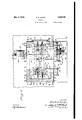
- the furnace comprises longitudinally extending parallel side walls 1, a transversely extending rear wall 2 and a transversely extending front wall 3 provided with a door opening 4 which may be closed by the usual vertically slidable door 5 and through which the charge to be annealed may be introduced on a suitable truck running on the usual tracks 6 6 extending longitudinally of the furnace at its center and let into the hearth 7 forming the bottom of the heating chamber 8 which is closed at its top by the roof 9 extending between the side and end walls and desirably slightly transversely arched as shown in Fig. 2.
- the walls of the furnace are supported exteriorly by the usual buckstays l disposed at suitable intervals and may desi
- each burner comprising suitable means for regulating the flow of air and fuel therethrough so that the temperature of the flame delivered by the burner into the furnace may be controlled.
- a flue l communieating with the interior of the furnace through longitudinally spaced ports 16 and communicating through a transverse flue 17 with the stack 18; by means of this flue Waste gases may be withdrawn from near the botV tom of the v chamber substantially uniformly along the hearth.
- dampers which may be of any form ⁇ suitable to regulate the flow of gases through the passages which they respectively control.
- I4 may thus provide the stack 18 with a damper 24 hingedly supported adjacent the top of the stack and provided with a counyterweight 25 and may in like manner provide each of the roof ports with a similar damper 26 supplied with a counterweight 27, and as the roof ports 22 are preferably each of smaller effective area than the stack, their dampers 26 will of course, and as shown, be correspondinglyl smaller than the stack damper 24, while the counterweights 25 and 27 are in each case suiiicient ⁇ to over-balance their respective dampers and thus urge the latter to openposition unless preventedfby ⁇ suitable controlling means, such,'for example, as thosewhich 1 have shown in the accompanying dra-wings and which l shall now proceed to describe.
- damper controlling means are well adapted for the performance of their intended function, particularly when employed in connection with the hinged and j counterweighted dampers to which I have referred, it will be understood that other forms of damper controlling means may be utilized if preferred either with dampers of that character or with dampers of other forms.
- eachof the roof dampers 26 may be provided withan arm '26 on the opposite side of the damper hinge from that on Vwhich the counterweight is disposed, to
- the shaft 36 is also provided with another drum v41 from Which a cable 42 extends upwardly over a sheave 43 on a shaft 44 extend- Y ing parallel to shaft 32 and journaled in suitable brackets 45 carried by the buckstays and thence to the arm 24 of the stack damper, in *sucht manner that the latter will be closed or opened in correspondence With the direction of rotation of the shaft 35, the respec# tive ldiameters' of the drums 35 and'41 being preferably so calculatedv and the other parts of the controlling mechanism preferably so arranged that when the roof dampers 26 are beingopened, the stack damper 24 is being correspondingly closed andvice versa; thus, when the latter is in fully closed position the roof dampers are opened to permit unrestrictedgflow of gases-through the roof ports and conversely, when the roof dampers are fully closed Vthe stack'damper is in fully opened position to permitunrestricted fiow of gases through the stack, while in intermediate positions' of the dampers'the degree of restriction
- a charge C such as an annealing box containing the material to be annealed, is disposed on the piers 2O with the aid of a charging truck Which is then withdrawn and the door closed in the usual manner, a plurality of pyrometer thermo-couples T being preferably distributed at different points in the Wall of the box or in the charge itself and connected as by Wires W to pyrometers (not shown) located outside the furnace to enable the temperature attained by various parts of the charge to be readily ascertained by the operator. Air and gas in suitable quantities are then admitted to the heating chamber through the burners 12, the combustion of the fuel producing the heating gases employed for heating the charge.
- the heat of the various portions of the charge is shown by the pyrometers or other indicating devices connected to the pyrometer thermo-couples distributed about the charge, and thus it may readily be determined which, if any, portion of the charge is receiving the proper amount of heat and Which portions, if any, are receiving greater or less than the required amount.
- the dampers 24 and 26 are operated by means of the crank 39, or other suitable means which may be provided for the purpose,in such manner that the flow of Waste gases through the roof ports is restricted and that through the flue 17 is enhanced, thus causing a greater proportion of the heating gases to flow adjacent the bottom of the charge, and restricting the flow of gases about the top thereof with corresponding regulation of the relative amounts of heat received by the different parts of the charge.
- a furnace of the class described comprising a heating chamber and a hearth disposed therebeneath, a flue extending from the hearth adapted to conduct Waste gases from the lower part of said chamber, means for introducing heating gases into said chamber, means adapted to conduct Waste gases from another part of said chamber, and interconnecting means for simultaneously and selectively controlling the floW of gases through both of said conducting means.
- a furnace of the class described comprising a heating chamber, means for introducing heating gases thereinto, means for conducting Waste gases from' dierent parts thereof, dempers operative to control the passage of said Waste gases through said conducting means, and means for simultaneously actuating said damper-s in opposite directions with respect to the conducting means respectively controlled thereby.
- a furnace of the class described comprising Wal1s,a hearth, and a roof enclosing a heating chamber, vmeans for introducing heating gases into said chamber, a lueextending in and leading from the lhearth adapted to conduct waste gases from the lower part of the chamber, said roof being provided With a plurality of spacedl ports also respectively adapted to conduct' Waste gases from the upper part of the chamber, a damper operative to control the flow of gases through the flue, dampers respectively 1 25 operative to control theiioW of gases through said ports, and means interconnected With lall of said dampers operable to move all of the lport controlling dampers in one direction with respect to the ports and to contempora- 80 neously move the lue controlling damper in the other direction with respect to the flue.
Landscapes
- Chemical & Material Sciences (AREA)
- Engineering & Computer Science (AREA)
- Physics & Mathematics (AREA)
- Thermal Sciences (AREA)
- Crystallography & Structural Chemistry (AREA)
- Mechanical Engineering (AREA)
- Materials Engineering (AREA)
- Metallurgy (AREA)
- Organic Chemistry (AREA)
- Furnace Details (AREA)
Description
Patented'May 3, 1932 f Y* UNITED STAPEES Y, Ensim afirmar, or ,rennes-frown, omo, AssreNon 'ro THE YoUNGsroWN SHEET Ann TUBE eoirraNY, or YoUNGsroWN, orrro, A conrona'rion or omo PATENT OFFICE IEUBNACE Application led, June 9, 1930. Serial No. 459,971.
AMy invention relates more particularly to furnaces of the type used forfbox annealing orf annealing sheets in packs.
In such furnacesas heretofore construct ed it hasbeenthe usualpractice'to'introduce thel heatinggases. on one side ofthe charge, which mayfconsist of the usualboX holding the materialtobe annealed, a pack of sheets or the like, thro-ugh'a burner positioned near tr the bottom and to. one side ofthe .heating chamber sothatthe flame is projected upwardly and over the'charge, then down the other side thereof, and finally under it to an outlet through which the waste gases can escape.` The `flame is thus. caused to encircle the charge, causingf'hot'spots. at some portiens thereof'andcol'd spots at others as the fiame cools down itstravel, with consequent` unevenness in theannealing, so that it `often becomes necessary to re-anneal the whole charge with resulting waste of fuel and labor as well as inereasedwear, tear and deterioration of the furnacevitself..
A principal object of my' invention, therefore, is to provide a novel form of furnace adapted for box annealing or the like by the usev of which the charge may be evenly and uniformly heated throughout and the unsatisfactory conditions vte which l have briefly referred thus entirely avoided. A further object of my invention isl the provision of a furnace of this. characterv in which the course o-f the heating gases in their traverse of the heating chamber may be so controlled that their heat is distributed evenly throughout the charge with resulting uniformity in the heating of all parts thereof; which is so constructed that it ispossible for the operator to alter the course of the heatingV gases at will soas to increase the localheatingl of one part of the charge over another when such increase is required to eliminate cold spots or reduce the tendency to overheating with censequent creation of a hotspot at some ypoint in the charge, and which is of simple design and construction and may be readily operated by Workmen of the ability of those usuallyemployed in the management of annealing furnaces.
j `My invention further comprehends general improvement of the design and construction of furnaces of the general class of those to which it relates, as well as other objects and novel features hereinafter more particularly pointed out or which will be apparent to those skilled in the art from the following description of a furnace constructed in accordance with one embodiment of my invention and illustrated in the accompanying A As shown, the furnace comprises longitudinally extending parallel side walls 1, a transversely extending rear wall 2 and a transversely extending front wall 3 provided with a door opening 4 which may be closed by the usual vertically slidable door 5 and through which the charge to be annealed may be introduced on a suitable truck running on the usual tracks 6 6 extending longitudinally of the furnace at its center and let into the hearth 7 forming the bottom of the heating chamber 8 which is closed at its top by the roof 9 extending between the side and end walls and desirably slightly transversely arched as shown in Fig. 2. The walls of the furnace are supported exteriorly by the usual buckstays l disposed at suitable intervals and may desirably be sheathed with metal 11.
For admitting the heating gasesA to thev heating chamber I provide a suitable burner l2 adjacent each corner thereof and situated a little above the level of the hearth, each burner comprising suitable means for regulating the flow of air and fuel therethrough so that the temperature of the flame delivered by the burner into the furnace may be controlled.
Beneath the hearth of the furnace and eX- tendinglongitudinally and substantially centrally thereof, is formed a flue l communieating with the interior of the furnace through longitudinally spaced ports 16 and communicating through a transverse flue 17 with the stack 18; by means of this flue Waste gases may be withdrawn from near the botV tom of the v chamber substantially uniformly along the hearth.
Disposed upon the hearth at laterally annealed, apack of sheets or the like; these piers are transversely pierced at intervals by openings 21 through which. the heating gases can circulate uniformly beneath the charge and thence into the ports 16 in the hearth. f At spaced lintervals in the roof of the furnace and substantially centrally thereof I 'provide ports-22 which may be of any desired number and shape, although I preferand have shown inthe accompanying drawings three such yports equidistantly spaced along the center line of the roof and each of circular cross section. n
For controlling the flow of gases from the furnace I also provide in association with the stack and the ports 22 which will, for convenience, be hereinafter termed the roof ports, damperswhich may be of any form` suitable to regulate the flow of gases through the passages which they respectively control.. I4 may thus provide the stack 18 with a damper 24 hingedly supported adjacent the top of the stack and provided with a counyterweight 25 and may in like manner provide each of the roof ports with a similar damper 26 supplied with a counterweight 27, and as the roof ports 22 are preferably each of smaller effective area than the stack, their dampers 26 will of course, and as shown, be correspondinglyl smaller than the stack damper 24, while the counterweights 25 and 27 are in each case suiiicient `to over-balance their respective dampers and thus urge the latter to openposition unless preventedfby` suitable controlling means, such,'for example, as thosewhich 1 have shown in the accompanying dra-wings and which l shall now proceed to describe. However, while the said means are well adapted for the performance of their intended function, particularly when employed in connection with the hinged and j counterweighted dampers to which I have referred, it will be understood that other forms of damper controlling means may be utilized if preferred either with dampers of that character or with dampers of other forms. j
Thus, as shown .eachof the roof dampers 26 may be provided withan arm '26 on the opposite side of the damper hinge from that on Vwhich the counterweight is disposed, to
j which is connected a cable 30 extending generally transversely ofthe roof to a drum 31 ksupported on a longitudinally extending horizontal shaft 32 Vjournaled in brackets 33 secured to the buckstays or any other convenient point adjacent the side wall of the furnace. The drums aresecured to the shaft as by set screws 34 so as to rotate therewith,
and all of the cables but one are carried about their respective drums andthe ends ythen secured thereto, so that las the shaft is rotated Y these cables will be either Wound 0r unwound from theirdrums. One of the cables, however, for example 30', instead 'of having its end secured to its drum, is carried there about for one or more turns and thence down- Wardly to another drum 35 disposed on a shaft 36 journaled in pedestals 37 mounted on a platform 38 .adjacent the side of the furnace or otherwise supported in any con` venient way@ This shaft extendsY at right angles to the shaft 32 and is provided with a crank 39 whereby it may be manually rotated, a locking screw 40 or other meansfor'holding the shaft in any position of rotational adjustment being preferably provided.
' Thus, when the shaft 39 is turned in such direction as to wind the cable 30- on the drum 35, the shaft 32 will be correspondingly rov tated in a direction to wind the cables 3() on their drums 31 which it supportsthereby simultaneously pulling all of the dampers 26 down from the position shown in Fig. 2 in opposition to their respective counterweights and toward .the roof ports which they res ectively control. Likewise, when the cran is rotated inthe other direction so as to unwind the cable 30 from the drum35, the counterweights on the dampers are effective to rotate the shaft 32 in reverse direction with consequent simultaneous opening of all of the roof dampers. i l
The shaft 36 is also provided with another drum v41 from Which a cable 42 extends upwardly over a sheave 43 on a shaft 44 extend- Y ing parallel to shaft 32 and journaled in suitable brackets 45 carried by the buckstays and thence to the arm 24 of the stack damper, in *sucht manner that the latter will be closed or opened in correspondence With the direction of rotation of the shaft 35, the respec# tive ldiameters' of the drums 35 and'41 being preferably so calculatedv and the other parts of the controlling mechanism preferably so arranged that when the roof dampers 26 are beingopened, the stack damper 24 is being correspondingly closed andvice versa; thus, when the latter is in fully closed position the roof dampers are opened to permit unrestrictedgflow of gases-through the roof ports and conversely, when the roof dampers are fully closed Vthe stack'damper is in fully opened position to permitunrestricted fiow of gases through the stack, while in intermediate positions' of the dampers'the degree of restriction :of the flow of .gases through the stack is maintained roughly in inverse proportion to the Adegree of restrictionof the icio [low through the roof ports. Thus, assuming that the capacity of the stack is substantially equa-l to the total capacity of the roof ports, th-e total amount of Waste gases flowing from the furnace is substantially constant regardless of the position of the various dampers, although it will be understood that the relative size or capacity of the stack and of the ports forms no part of my invention.
The operation of a furnace constructed substantially as just described is as follows: A charge C, such as an annealing box containing the material to be annealed, is disposed on the piers 2O with the aid of a charging truck Which is then withdrawn and the door closed in the usual manner, a plurality of pyrometer thermo-couples T being preferably distributed at different points in the Wall of the box or in the charge itself and connected as by Wires W to pyrometers (not shown) located outside the furnace to enable the temperature attained by various parts of the charge to be readily ascertained by the operator. Air and gas in suitable quantities are then admitted to the heating chamber through the burners 12, the combustion of the fuel producing the heating gases employed for heating the charge. As the temperature Within the furnace is raised, the heat of the various portions of the charge is shown by the pyrometers or other indicating devices connected to the pyrometer thermo-couples distributed about the charge, and thus it may readily be determined which, if any, portion of the charge is receiving the proper amount of heat and Which portions, if any, are receiving greater or less than the required amount. Such determination having been made and assuming that the top of the charge is receiving too great an amount of heat in proportion to that received by the bottom of the charge, the dampers 24 and 26 are operated by means of the crank 39, or other suitable means which may be provided for the purpose,in such manner that the flow of Waste gases through the roof ports is restricted and that through the flue 17 is enhanced, thus causing a greater proportion of the heating gases to flow adjacent the bottom of the charge, and restricting the flow of gases about the top thereof with corresponding regulation of the relative amounts of heat received by the different parts of the charge. Conversely, if the bottom of the charge is receiving too great a proportion of the heat supplied to the furnace, this situation may be readily corrected by moving the dampers respectively in o-pposite directions from those just referred to, that is, by opening the roof dampers more Widely to cause larger quantities of the heating gases to flow over the top of the charge so as to increase the temperature of the latter, While correspondingly moving the stack damper to a position further restricting the passage of gases through 'the Stack andk consequently decreasing' the proportion of gas flowing adjacent andsupplying heat to the bottom of the charge.
Thus, byv noting the temperature of the variousl parts of the charge from time to time and correspondingly regulating the roof port and stack dampers to properly direct the flow of the gases, a very even and uniform heating ofthe entire charge may he obtained even-under conditions of operation, such as high Winds causing excessive stack draft or therlilie, which are highly inimical thereto. -While I' have referred more especially to a formf of damper control means adapted for' manual operation, it Will be apparent to those skilled in the art that, if desired, the respective dampers may be operated by suitable automatic means, as for example, an electric motor arranged to drive the shaft 36, and
Which may be so interconnected with the heat indicating pyrometers, in a Welldmown manner, as to pro 7ide fully automatic operation of the dempers and uniform and efficient heating of the charge Substantially Without' lattention from plant operatives during the heating period.
While l have herein shown andv described with considerable particularity` a furnace constructed in accordance with one embodiment of my invention, it will nevertheless be u'nderstoodthat I do not thereby desire or intend to restrict myself specifically thereto, as numerous changes and modifications may he made in the form and arrangement of the various parts and in the manner of their association with each other, if desired, Without departing from the spirit and scope of the invention as defined in the appended claims.
Having thus described my invention, I claim and desire to protect by Letters Patent of the United States:
l. A furnace of the class described comprising a heating chamber and a hearth disposed therebeneath, a flue extending from the hearth adapted to conduct Waste gases from the lower part of said chamber, means for introducing heating gases into said chamber, means adapted to conduct Waste gases from another part of said chamber, and interconnecting means for simultaneously and selectively controlling the floW of gases through both of said conducting means.
2. A furnace of the class described comprising a heating chamber, means for introducing heating gases thereinto, means for conducting Waste gases from' dierent parts thereof, dempers operative to control the passage of said Waste gases through said conducting means, and means for simultaneously actuating said damper-s in opposite directions with respect to the conducting means respectively controlled thereby.
3. A furnace of the class described coin -prising a heating chamber, means for introducing heating gases thereinto, means for conducting Waste gases therefrom, dampers respectively operative to control said conf, ducting means, and means for simultaneouslyractuating said dampers in Such manner M that the relative proportional restriction of the flow of Waste gases through one of said conducting means is maintained in substan- Y A tiallyinverse ratio to the relative proportionsaid' conducting means. 4. A furnace of the class described comprising Wal1s,a hearth, and a roof enclosing a heating chamber, vmeans for introducing heating gases into said chamber, a lueextending in and leading from the lhearth adapted to conduct waste gases from the lower part of the chamber, said roof being provided With a plurality of spacedl ports also respectively adapted to conduct' Waste gases from the upper part of the chamber, a damper operative to control the flow of gases through the flue, dampers respectively 1 25 operative to control theiioW of gases through said ports, and means interconnected With lall of said dampers operable to move all of the lport controlling dampers in one direction with respect to the ports and to contempora- 80 neously move the lue controlling damper in the other direction with respect to the flue.
In Witness whereof, I have hereunto set my hand this 6th day of June, 1930. i i
p FRANK E.- LEAI-IY.
al restriction ofl said flowk through other of Y
Priority Applications (1)
| Application Number | Priority Date | Filing Date | Title |
|---|---|---|---|
| US459971A US1856645A (en) | 1930-06-09 | 1930-06-09 | Furnace |
Applications Claiming Priority (1)
| Application Number | Priority Date | Filing Date | Title |
|---|---|---|---|
| US459971A US1856645A (en) | 1930-06-09 | 1930-06-09 | Furnace |
Publications (1)
| Publication Number | Publication Date |
|---|---|
| US1856645A true US1856645A (en) | 1932-05-03 |
Family
ID=23826894
Family Applications (1)
| Application Number | Title | Priority Date | Filing Date |
|---|---|---|---|
| US459971A Expired - Lifetime US1856645A (en) | 1930-06-09 | 1930-06-09 | Furnace |
Country Status (1)
| Country | Link |
|---|---|
| US (1) | US1856645A (en) |
-
1930
- 1930-06-09 US US459971A patent/US1856645A/en not_active Expired - Lifetime
Similar Documents
| Publication | Publication Date | Title |
|---|---|---|
| US3997317A (en) | Glass annealing lehr having gas and electric heating means | |
| US1923145A (en) | Method and apparatus for heat treating | |
| US1856645A (en) | Furnace | |
| US838270A (en) | Baking-oven. | |
| US2069542A (en) | Furnace | |
| US901956A (en) | Annealing-furnace. | |
| US2805143A (en) | Method and apparatus for heating metal | |
| US1421155A (en) | Tunnel kiln | |
| US2016458A (en) | Method of direct heating of materials in furnaces | |
| US2262609A (en) | Furnace for coating baths | |
| US1814567A (en) | Recirculating system and apparatus for waste furnace gases | |
| US2222673A (en) | Incineration | |
| US786565A (en) | Annealing-furnace. | |
| US2118502A (en) | Drier furnace | |
| US1536226A (en) | Device for operating open-hearth-furnace dampers | |
| US2189167A (en) | Baking oven | |
| US1828833A (en) | Glass melting furnace | |
| US1775281A (en) | Leer | |
| US1394164A (en) | Oil-burning furnace | |
| US1561390A (en) | Continuous-conveyer bake oven | |
| US183140A (en) | Improvement in pottery-kilns | |
| US693359A (en) | Brick-drier. | |
| US1464002A (en) | Method of and apparatus for reversing and controlling regenerative furnaces | |
| US2256275A (en) | Enameling furnace | |
| US1746155A (en) | Baking apparatus |