US1856635A - Mechanically operated brake - Google Patents
Mechanically operated brake Download PDFInfo
- Publication number
- US1856635A US1856635A US462337A US46233730A US1856635A US 1856635 A US1856635 A US 1856635A US 462337 A US462337 A US 462337A US 46233730 A US46233730 A US 46233730A US 1856635 A US1856635 A US 1856635A
- Authority
- US
- United States
- Prior art keywords
- cylinder
- brake
- vacuum
- lever
- valve
- Prior art date
- Legal status (The legal status is an assumption and is not a legal conclusion. Google has not performed a legal analysis and makes no representation as to the accuracy of the status listed.)
- Expired - Lifetime
Links
- 230000000694 effects Effects 0.000 description 5
- 238000010276 construction Methods 0.000 description 3
- 239000004020 conductor Substances 0.000 description 2
- 230000000994 depressogenic effect Effects 0.000 description 2
- 230000000087 stabilizing effect Effects 0.000 description 2
- 241001550206 Colla Species 0.000 description 1
- 230000015572 biosynthetic process Effects 0.000 description 1
- 239000000314 lubricant Substances 0.000 description 1
- 238000012856 packing Methods 0.000 description 1
- 230000000717 retained effect Effects 0.000 description 1
Images

Classifications
-
- B—PERFORMING OPERATIONS; TRANSPORTING
- B60—VEHICLES IN GENERAL
- B60T—VEHICLE BRAKE CONTROL SYSTEMS OR PARTS THEREOF; BRAKE CONTROL SYSTEMS OR PARTS THEREOF, IN GENERAL; ARRANGEMENT OF BRAKING ELEMENTS ON VEHICLES IN GENERAL; PORTABLE DEVICES FOR PREVENTING UNWANTED MOVEMENT OF VEHICLES; VEHICLE MODIFICATIONS TO FACILITATE COOLING OF BRAKES
- B60T13/00—Transmitting braking action from initiating means to ultimate brake actuator with power assistance or drive; Brake systems incorporating such transmitting means, e.g. air-pressure brake systems
- B60T13/10—Transmitting braking action from initiating means to ultimate brake actuator with power assistance or drive; Brake systems incorporating such transmitting means, e.g. air-pressure brake systems with fluid assistance, drive, or release
- B60T13/58—Combined or convertible systems
- B60T13/588—Combined or convertible systems both fluid and mechanical assistance or drive
Definitions
- This invention relates to vehicle brakes
- the invention has for a further object to provide a brake of the character stated which shall embody mechanical means for creating N the vacuum employed to effect the applica- 1 tion of the brake bands and wherein such means shall be adapted to be controlled by the driver of the automobile in a manner to permit the brake bands to be applied slowly or rapidly as conditions may require.
- the invention has for a further object to provide a brake of the character stated wherein the mechanical means shall be adapted to effect the steady or uniform application of the brake bands whether it is operated to effect slow or rapid application of the brake bands.
- the invention has for a still further object to provide a brake of the character stated which shall be simple, durable and capable of being manufactured at a comparatively low cost, and which shall be adapted to be readily installed and maintained in a high state of efficiency with comparatively little or no attention.
- Figure 2 is a diagrammatic View of the means for controlling the operation of the brake
- Figure 3 is a sectional view illustrating the type of piston valve employed in the vacuum P m e Figure 4 1s a sectlonal vlew taken on a plane extending vertically through the brake shaft and axle housing; and
- Fi re 5 is a sectional view illustrating the 1930. Serial No. 462,337.
- 1 designates the chassis
- 2 the rear wheels and 3 the front wheels of an automobile truck of well known construction
- 4 designates the rear axle housing
- 5 the brake drums and 6 the brake bands of the truck.
- the brake bands 6 are connected in the usual manner, as shown at 7, to a shaft 8 which is journaled, as at 8a, on the axle housing 4, and is provided at its center with a crank 9.
- a brake cylinder 10 is secured to the chassis l forwardly of and in longitudinal alinement with the crank 9.
- the brake cylinder 10 is provided at its rear side with a flexible head or diaphragm 11 to which is connected a rod 12.
- the diaphragm 11 is provided at its inner and outer sides with washers 13 and 14 through which the rod 12 extends.
- the rod 12 is screw threadedly engaged with the washers 13 and 14, and is held against accidental turning movement with respect thereto by nuts 15 and 16.
- a link 12a which is connected to the rod 12 is connected to the crank 9 by a pin 17.
- the cylinder 10 and diaphragm 11 are of similar formation and are provided with outer flanges 10 and 11 to permit them to be secured together by bolts 19, packing being arranged between the flanges to render the connection between the cylinder and diaphragm air-proof.
- a vacuum pump 21 is mounted upon the chassis 1 at one side of the cylinder 10, and comprises a cylinder block 22, a head 23 and a crank case 24.
- the block 22 has two cylinders 25 in which are reciprocably mounted pistons 26.
- the pistons 26 are provided in their heads with inwardly facing conical valve seats 27 and associated with said seats are conical valves 28 which are yieldingly retained seated by springs 29.
- the valves 28 remain seated during the inner strokes and unseat during the outer strokes of the piston 26.
- the pistons 26 are connected by rods 30 to a crank shaft 31 which is journaled in bearings 32 carried by the block 22.
- the crank case 24 is adapted to contain lubricant for pump 21.
- Oneend of the tank 36" is connected to the cylinder 10 by a ,pipe 37, andthe other end of the tank is connected by a pipe 38 and check valves 39 to' the cylinders12.5;
- the check valves 39 seat outwardly to permit the operations.ofthezpistons 26 to create a Vacuum inthe. cylinder :10 and tank 36.
- Themotor 33 is supplied with currentfrom the storage'battery 40 of the. automobile,and the supply of current thereto is controlled by a rheostat 41.
- One side of the battery 40and one of the brushes of the motor 33 are grounded .to the chassis l.
- the other brush of-the motor33 is connectedby a conductor 42 to the resistance element 43 of the rheostat 41, and thebl-ade 44 ofthe rheostat is connectedfby a conductor 45-tothe other side of the battery .40.
- the rheostat 41 . is of well vknown: construction,-and the blade :44 thereof is connectedabya link 4.6 to the lower end of a'pedal lever/i7 which is pivoted interzmediateitsends, asat 48, to the chassis 1.
- a spring 49 which is secured at oneend to the chassis land atthe other end to the lower .end. of the lever 47, serves to normally hold :the blade 44 in circuit breaking position.
- the lever 47' provides means through the medium of which the driver .ofthe automobile may m'ovethe blade 44 into circuit closing position when it is desired to effect the application of the brake bands 6.
- the rapidity of the application of the brake bands 6' will depend'upon the distance through which the blade 44 is moved,as will be understood;
- a normally closed pressure actuated switch 50 is interposed in the conductor-42'.
- the means for actuating this switch comprises a chamber '51 provided with a flexible diaphragm -52 and connected'to the cylinder 10 by a'pipe 53.
- a spring 54 arranged “in :the chamber 51 and bearing against the "diaphragm 52 serves to maintain the switch 50 normally closed.
- a vacuum is simultaneously created in the cylinder 10 and chamber 51, and when suflicient air has been exhausted from these parts to permit the application of the brake bands, the diaphragm 52 is moved inwardly. This movement of the diaphragm 52-resultsin the opening of the switch 50 and the consequent stopping of the motor 33 and p'ump 21.
- valve 56 which controls communication of the pipe with the atmosphere.
- valve 56 has its stem 57 arranged in contact with theifront side of the lever 47 so as to permit it to be normally held opened by the spring 49.
- a spring 58 functions to close the valve 56 during the first phase of the movementof thelever 47 when the latter is forwardly depressed orswung in the direction .indicated by the arrow of Figure 2, the remaining phase of this movement of the .lever serving to move the blade 44 into circuit closing position.
- the lever 47 Upon being released, the lever 47 is swung in the opposite direction or rearwardly by the spring 49, and during the first phase of this movement of the lever, the rheostat blade 44 is moved into circuit breaking position and during the final phase of this movement of the lever, the valve 56 is opened by its spring 57, the opening of the valve breaking the vacuum in the cylinder 10, tank 36 and chamber 51 to permit the brake bands 6 to be moved into released position by their springs and to permit the closing of the switch 50 by its spring 54:.
- the rapidity of the applicationof the brake bands 6 depends upon the rapidity with which the lever 47 is depressed, it being thus apparent that the brake bands may be applied as slowly or quickly as conditions may require.
- the tank 36 stabilizes the creation of the vacuum in the cylinder 10, and this effects the application of the brake bands 6 in asteady or uniform manner.
- I claim 1.'A vehicle brake comprising breaking elements, a cylinder having a flexible head connected to said elements, a vacuum pump connected to the cylinder, a normally idle motor for the pump, a normally opened release valve connected to the cylinder, and means by which the motor may be operated .and the valve closed.
- a vehicle brake comprising breaking elements, a cylinder having a flexible head connected to said elements, a vacuum stabilizing tank connected to the cylinder, a vacuum pump connected to the tank, a. normally idle motor for the pump, a normally opened release valve connected to the cylinder, and means for starting the motor and closing the valve.
- a vehicle brake comprising breaking elements, a cylinder having a flexible head connected to said elements, a vacuum pump connected to the cylinder, an electric motor for the pump, a source of current connected to the motor, a switch in said connection, a normally opened release valve connected to the cylinder, and means normally holding the switch opened and adapted to be operated to close the switch and valve.
- a vehicle brake comprising breaking elements, a cylinder having a flexible head connected to said elements, a vacuum pump connected to the cylinder, an electric motor for the pump, a source of current connected to the motor, a rheostat having a movable der and bearing against the lever, the lever being adapted to be rocked to move the blade into circuit closing position and to close the valve.
- a vehicle brake comprising breaking elements, a cylinder having a flexible head connected to said elements, a vacuum pump connected to the cylinder, an electric motor for the pump, a source of current connected to the motor, a normally opened switch in said connection, a normally opened release valve connected to the cylinder, means by which the switch and valve may be closed, and a normally closed pressure actuated switch in said connection and connected to the cylinder.
- a vehicle brake comprising breaking elements, a cylinder having a flexible head connected to said elements, a vacuum stabilizing tank connected to the cylinder, a vacuum pump connected to the tank, an electric motor for the pump, a soure of current connected to the motor, a rheostat having a blade and arranged in said connection, a pivoted lever connected to the blade, a spring acting through the lever to normally hold the blade in circuit breaking position, a normally opened release valve connected to the cylinder and bearing against the lever, the lever being adapted to be operated to move the blade into circuit closing position and to close the valve, and a normally closed pressure operated switch in said connection and connected to the cylinder, said last switch being adapted to be opened on the creation of a predetermined vacuum in the cylinder.
Landscapes
- Engineering & Computer Science (AREA)
- Transportation (AREA)
- Mechanical Engineering (AREA)
- Valves And Accessory Devices For Braking Systems (AREA)
Description
y 3, 1932- E. R. HERREN MECHANICALLY OPERATED BRAKE 2 Sheets-Sheet Filed June 19, 1950 Mung May 3, E, R. HE
MECHANICALLY OPERATED BRAKE Filed June 19, 1930 2 Sheets-Sheet 2 Patented May 3, 1932 EARL R. HERREN,
PATENT OFFICE OF LORAIN, OHIO MECHANICALLY OPERATED BRAKE Application filed June 19,
This invention relates to vehicle brakes,
and has for one of its objects to provide a novel vacuum brake for automobiles of all types and particularly for trucks and their 5 trailers.
The invention has for a further object to provide a brake of the character stated which shall embody mechanical means for creating N the vacuum employed to effect the applica- 1 tion of the brake bands and wherein such means shall be adapted to be controlled by the driver of the automobile in a manner to permit the brake bands to be applied slowly or rapidly as conditions may require.
The invention has for a further object to provide a brake of the character stated wherein the mechanical means shall be adapted to effect the steady or uniform application of the brake bands whether it is operated to effect slow or rapid application of the brake bands.
The invention has for a still further object to provide a brake of the character stated which shall be simple, durable and capable of being manufactured at a comparatively low cost, and which shall be adapted to be readily installed and maintained in a high state of efficiency with comparatively little or no attention.
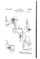
With the foregoing and other objects in View, the nature of which will appear as the description proceeds,,the invention consists in the construction, combination and arrangement of parts hereinafter fully described and claimed, and illustrated in the accompanying drawings, wherein Figure 1 is a view partly in top plan and partly in horizontal section illustratingthe application of the brake to an automobile truck;
Figure 2 is a diagrammatic View of the means for controlling the operation of the brake;
Figure 3 is a sectional view illustrating the type of piston valve employed in the vacuum P m e Figure 4 1s a sectlonal vlew taken on a plane extending vertically through the brake shaft and axle housing; and
Fi re 5 is a sectional view illustrating the 1930. Serial No. 462,337.
type of check valve employed between the vacuum tank and vacuum pump.
Referring in detail to the drawings, 1 designates the chassis, 2 the rear wheels and 3 the front wheels of an automobile truck of well known construction. 4 designates the rear axle housing, 5 the brake drums and 6 the brake bands of the truck. The brake bands 6 are connected in the usual manner, as shown at 7, to a shaft 8 which is journaled, as at 8a, on the axle housing 4, and is provided at its center with a crank 9.
In accordance with my invention, a brake cylinder 10 is secured to the chassis l forwardly of and in longitudinal alinement with the crank 9. The brake cylinder 10 is provided at its rear side with a flexible head or diaphragm 11 to which is connected a rod 12. The diaphragm 11 is provided at its inner and outer sides with washers 13 and 14 through which the rod 12 extends. The rod 12 is screw threadedly engaged with the washers 13 and 14, and is held against accidental turning movement with respect thereto by nuts 15 and 16. A link 12a which is connected to the rod 12 is connected to the crank 9 by a pin 17. The cylinder 10 and diaphragm 11 are of similar formation and are provided with outer flanges 10 and 11 to permit them to be secured together by bolts 19, packing being arranged between the flanges to render the connection between the cylinder and diaphragm air-proof.
A vacuum pump 21 is mounted upon the chassis 1 at one side of the cylinder 10, and comprises a cylinder block 22, a head 23 and a crank case 24. The block 22 has two cylinders 25 in which are reciprocably mounted pistons 26. The pistons 26 are provided in their heads with inwardly facing conical valve seats 27 and associated with said seats are conical valves 28 which are yieldingly retained seated by springs 29. The valves 28 remain seated during the inner strokes and unseat during the outer strokes of the piston 26.
The pistons 26 are connected by rods 30 to a crank shaft 31 which is journaled in bearings 32 carried by the block 22. The crank case 24 is adapted to contain lubricant for pump 21. Oneend of the tank 36"is connected to the cylinder 10 by a ,pipe 37, andthe other end of the tank is connected by a pipe 38 and check valves 39 to' the cylinders12.5; The check valves 39 seat outwardly to permit the operations.ofthezpistons 26 to create a Vacuum inthe. cylinder :10 and tank 36.
When a vacuum: is created in the cylinder 10, the diaphragm ll is collapsed or moved forwardly withrespect to the cylinder by atmospheric pressure, and the;colla,psing or movement ofzthe diaphragm resultsin the application of the brake bands 6. j lVhenthe vacuum in the cylinder 10 is broken, the diaphragm llvreturns to its original condition or moves rearwardly, and the restoration of the diaphragm to its original condition or movement thereof results in the release of the brake bands '6 which. areflrestored' totheir by springs, not shown.
normalinactive positionzin the usual manner Themotor 33 is supplied with currentfrom the storage'battery 40 of the. automobile,and the supply of current thereto is controlled by a rheostat 41. One side of the battery 40and one of the brushes of the motor 33 are grounded .to the chassis l. The other brush of-the motor33 is connectedby a conductor 42 to the resistance element 43 of the rheostat 41, and thebl-ade 44 ofthe rheostat is connectedfby a conductor 45-tothe other side of the battery .40. The rheostat 41 .is of well vknown: construction,-and the blade :44 thereof is connectedabya link 4.6 to the lower end of a'pedal lever/i7 which is pivoted interzmediateitsends, asat 48, to the chassis 1. A spring 49, which is secured at oneend to the chassis land atthe other end to the lower .end. of the lever 47, serves to normally hold :the blade 44 in circuit breaking position. The lever 47' provides means through the medium of which the driver .ofthe automobile may m'ovethe blade 44 into circuit closing position when it is desired to effect the application of the brake bands 6. The rapidity of the application of the brake bands 6'will depend'upon the distance through which the blade 44 is moved,as will be understood;
A normally closed pressure actuated switch 50 "is interposed in the conductor-42'. The means for actuating this switch comprisesa chamber '51 provided with a flexible diaphragm -52 and connected'to the cylinder 10 by a'pipe 53. A spring 54 arranged "in :the chamber 51 and bearing against the "diaphragm 52 serves to maintain the switch 50 normally closed. A vacuum is simultaneously created in the cylinder 10 and chamber 51, and when suflicient air has been exhausted from these parts to permit the application of the brake bands, the diaphragm 52 is moved inwardly. This movement of the diaphragm 52-resultsin the opening of the switch 50 and the consequent stopping of the motor 33 and p'ump 21. The stopping of the pump 21 'does'not permit the release of the brake bandsfi, andthey will not be released until the va'cuum'i n the cylinder 10 and chamber 51 isbroken,
To permit the vacuum to be broken and the consequentreleasingof the brake bands .6,-a.release pipe 55is connected at one end .to the cyliIlderlOQand isprovided at its other end with avalve 56' which controls communication of the pipe with the atmosphere. '1 he valve 56 has its stem 57 arranged in contact with theifront side of the lever 47 so as to permit it to be normally held opened by the spring 49. A spring 58 functions to close the valve 56 during the first phase of the movementof thelever 47 when the latter is forwardly depressed orswung in the direction .indicated by the arrow of Figure 2, the remaining phase of this movement of the .lever serving to move the blade 44 into circuit closing position. It will thus be seen that communication between the cylinder 10 and the atmosphere will be cut ofi immediately "prior to the operation of the pump 21 to create a vacuum in-the cylinder, the creation of the vacuum resulting in the application of the brake bands 6. b
It should be understood from theforegoing description, taken in connection with the ac- -.com ptanying drawings, that the spring 49 rnormally supports thelever 47 in upright 'position, and that 'whenthe lever is in this position, .the rheostat blade 44iis in motor circuit breaking position and the valve-5.6is opened. When the parts areintheseposi- ,tions, the vacuum pump 21 is at rest,'the cylinder,l0-is inscommunication with theatmo'sphere and the brakeba-nds 6 are released.
,To apply the brakebands 6, itis only (necessary to depress the lever 47 in a forward direction, During the first phase ofthe movementof thelever47 the valve56 is released for closing by its spring 58, and du-ringthe remaining phase of this movement of the lever, the rheostat blade 44 is moved into motor circuit closing position. As the pump 21 .isnow operating and as the valve 56 is closed, a vacuum is created in the tank 36, cylinder 10, and chamber51, "the creation of the vvacuum :permitting the diaphragm .11 to be moved by atmospheric pressure in a direction to apply the brakebands 6. Onthe fullapplication :of the brake Tbands v6, a jsuffi'cient vacuum will be created in the chamber 51 to permi t the 'openin'g of the switch 50; The
stopping of the pump 21, as the result of the opening of the switch 50, will not release the brake bands 6 which will remain applied until the lever 47 is released.
Upon being released, the lever 47 is swung in the opposite direction or rearwardly by the spring 49, and during the first phase of this movement of the lever, the rheostat blade 44 is moved into circuit breaking position and during the final phase of this movement of the lever, the valve 56 is opened by its spring 57, the opening of the valve breaking the vacuum in the cylinder 10, tank 36 and chamber 51 to permit the brake bands 6 to be moved into released position by their springs and to permit the closing of the switch 50 by its spring 54:. The rapidity of the applicationof the brake bands 6 depends upon the rapidity with which the lever 47 is depressed, it being thus apparent that the brake bands may be applied as slowly or quickly as conditions may require. The tank 36 stabilizes the creation of the vacuum in the cylinder 10, and this effects the application of the brake bands 6 in asteady or uniform manner.
I claim 1.'A vehicle brake, comprising breaking elements, a cylinder having a flexible head connected to said elements, a vacuum pump connected to the cylinder, a normally idle motor for the pump, a normally opened release valve connected to the cylinder, and means by which the motor may be operated .and the valve closed.
2. A vehicle brake, comprising breaking elements, a cylinder having a flexible head connected to said elements, a vacuum stabilizing tank connected to the cylinder, a vacuum pump connected to the tank, a. normally idle motor for the pump, a normally opened release valve connected to the cylinder, and means for starting the motor and closing the valve.
3. A vehicle brake, comprising breaking elements, a cylinder having a flexible head connected to said elements, a vacuum pump connected to the cylinder, an electric motor for the pump, a source of current connected to the motor, a switch in said connection, a normally opened release valve connected to the cylinder, and means normally holding the switch opened and adapted to be operated to close the switch and valve.
4. A vehicle brake, comprising breaking elements, a cylinder having a flexible head connected to said elements, a vacuum pump connected to the cylinder, an electric motor for the pump, a source of current connected to the motor, a rheostat having a movable der and bearing against the lever, the lever being adapted to be rocked to move the blade into circuit closing position and to close the valve.
5. A vehicle brake, comprising breaking elements, a cylinder having a flexible head connected to said elements, a vacuum pump connected to the cylinder, an electric motor for the pump, a source of current connected to the motor, a normally opened switch in said connection, a normally opened release valve connected to the cylinder, means by which the switch and valve may be closed, and a normally closed pressure actuated switch in said connection and connected to the cylinder.
6. A vehicle brake, comprising breaking elements, a cylinder having a flexible head connected to said elements, a vacuum stabilizing tank connected to the cylinder, a vacuum pump connected to the tank, an electric motor for the pump, a soure of current connected to the motor, a rheostat having a blade and arranged in said connection, a pivoted lever connected to the blade, a spring acting through the lever to normally hold the blade in circuit breaking position, a normally opened release valve connected to the cylinder and bearing against the lever, the lever being adapted to be operated to move the blade into circuit closing position and to close the valve, and a normally closed pressure operated switch in said connection and connected to the cylinder, said last switch being adapted to be opened on the creation of a predetermined vacuum in the cylinder.
In testimony whereof I hereunto aflix my signature.
EARL R. HERREN.
blade and arranged in said connection, a pivoted lever connected to the rheostat, a spring acting through the lever to hold the blade in circuit breaking position, and a normally opened release valve connected to the cylin-
Priority Applications (1)
| Application Number | Priority Date | Filing Date | Title |
|---|---|---|---|
| US462337A US1856635A (en) | 1930-06-19 | 1930-06-19 | Mechanically operated brake |
Applications Claiming Priority (1)
| Application Number | Priority Date | Filing Date | Title |
|---|---|---|---|
| US462337A US1856635A (en) | 1930-06-19 | 1930-06-19 | Mechanically operated brake |
Publications (1)
| Publication Number | Publication Date |
|---|---|
| US1856635A true US1856635A (en) | 1932-05-03 |
Family
ID=23836071
Family Applications (1)
| Application Number | Title | Priority Date | Filing Date |
|---|---|---|---|
| US462337A Expired - Lifetime US1856635A (en) | 1930-06-19 | 1930-06-19 | Mechanically operated brake |
Country Status (1)
| Country | Link |
|---|---|
| US (1) | US1856635A (en) |
Cited By (4)
| Publication number | Priority date | Publication date | Assignee | Title |
|---|---|---|---|---|
| US2844003A (en) * | 1953-08-31 | 1958-07-22 | Kelsey Hayes Co | Emergency power hook-up for booster brake mechanism |
| US3114498A (en) * | 1960-02-15 | 1963-12-17 | Westinghouse Air Brake Co | Vacuum pump unloading apparatus |
| US3420579A (en) * | 1967-05-03 | 1969-01-07 | Dole Valve Co | Vacuum operated brake system |
| EP0089081A1 (en) * | 1982-03-16 | 1983-09-21 | SAB NIFE AB (reg. no. 556010-0058) | A hydraulic brake system for vehicles |
-
1930
- 1930-06-19 US US462337A patent/US1856635A/en not_active Expired - Lifetime
Cited By (4)
| Publication number | Priority date | Publication date | Assignee | Title |
|---|---|---|---|---|
| US2844003A (en) * | 1953-08-31 | 1958-07-22 | Kelsey Hayes Co | Emergency power hook-up for booster brake mechanism |
| US3114498A (en) * | 1960-02-15 | 1963-12-17 | Westinghouse Air Brake Co | Vacuum pump unloading apparatus |
| US3420579A (en) * | 1967-05-03 | 1969-01-07 | Dole Valve Co | Vacuum operated brake system |
| EP0089081A1 (en) * | 1982-03-16 | 1983-09-21 | SAB NIFE AB (reg. no. 556010-0058) | A hydraulic brake system for vehicles |
Similar Documents
| Publication | Publication Date | Title |
|---|---|---|
| US867282A (en) | Steering-gear for automobiles. | |
| US2365960A (en) | Clutch or brake operating mechanism | |
| US1856635A (en) | Mechanically operated brake | |
| US1548394A (en) | Vehicle braking system | |
| US2296003A (en) | Automatic vehicle control | |
| US2571885A (en) | Tractor-trailer brake system | |
| US3094843A (en) | Automatic emergency power for vacuum powered braking systems | |
| US2102834A (en) | Brake | |
| USRE23081E (en) | Apparatus including power unit for | |
| US2185936A (en) | Safety automatic stopping device for automobiles and the like vehicles | |
| US3002791A (en) | Emergency power brake system | |
| US2933160A (en) | Power brake system emergency control | |
| CN203485908U (en) | A pneumatic brake master valve | |
| US2226671A (en) | Control mechanism | |
| US2464327A (en) | Vehicle brake system | |
| GB312350A (en) | Improvements in brake system for automotive vehicles | |
| US2112962A (en) | Pneumatic steering device | |
| US2634742A (en) | Valve for advancing trailer brake operation | |
| US1488017A (en) | Brake mechanism | |
| US1244606A (en) | Vehicle-brake. | |
| US1466549A (en) | Brake for vehicles | |
| US1972552A (en) | Vacuum operated jack | |
| US794382A (en) | Automobile-brake. | |
| US1928566A (en) | Power braking and clutch releasing mechanism for automotive vehicles | |
| US1538193A (en) | Fluid or safety gas brake for automobiles |