US1856629A - Scooping attachment for tractors - Google Patents
Scooping attachment for tractors Download PDFInfo
- Publication number
- US1856629A US1856629A US474866A US47486630A US1856629A US 1856629 A US1856629 A US 1856629A US 474866 A US474866 A US 474866A US 47486630 A US47486630 A US 47486630A US 1856629 A US1856629 A US 1856629A
- Authority
- US
- United States
- Prior art keywords
- fork
- scoop
- tractor
- beams
- frame
- Prior art date
- Legal status (The legal status is an assumption and is not a legal conclusion. Google has not performed a legal analysis and makes no representation as to the accuracy of the status listed.)
- Expired - Lifetime
Links
- 239000000463 material Substances 0.000 description 6
- 230000007246 mechanism Effects 0.000 description 5
- 239000011435 rock Substances 0.000 description 4
- 230000010355 oscillation Effects 0.000 description 3
- 230000009471 action Effects 0.000 description 2
- 230000006835 compression Effects 0.000 description 2
- 238000007906 compression Methods 0.000 description 2
- 230000005484 gravity Effects 0.000 description 2
- 210000003608 fece Anatomy 0.000 description 1
- 239000010871 livestock manure Substances 0.000 description 1
- 230000004048 modification Effects 0.000 description 1
- 238000012986 modification Methods 0.000 description 1
- 239000010902 straw Substances 0.000 description 1
Images

Classifications
-
- A—HUMAN NECESSITIES
- A01—AGRICULTURE; FORESTRY; ANIMAL HUSBANDRY; HUNTING; TRAPPING; FISHING
- A01D—HARVESTING; MOWING
- A01D87/00—Loaders for hay or like field crops
- A01D87/08—Loaders for hay or like field crops with sweep rakes, i.e. buck-rakes, e.g. transporting rakes
Definitions
- This invention relates to improvements in power operated scoops or forks and pertains particularly to a material handling fork mounted for power operation'upon a tractor.
- the primary object of the present invention is to provide a push fork carried and operated by a tractor so constructed that it may be shoved along the surface of the ground to pick up straw, manure or other material, without digging into the ground.
- Another object of the invention is to provide a tractor carried scoop fork having novel and improved means for mounting it upon the tractor whereby strain will not be trans.- ferred from the fork structure to the frame of the tractor but will be carried by the tractor draw bar.
- a still further object of the invention is to provide a tractor carried fork having associated therewith novel means whereby it may be dumped and automaticallyreturned to its former position, the means bywhich the fork is returned to operative position being actuated by power developed throughthe tipping of the fork under the action of gravity, when it is released.
- Still another object of the invention is to provide a tractor carried scoop fork which ma be raised or lowered for transportation or or a scooping operation and which has associated therewith a braking device whereby the fork may be held in fully raised position or a position intermediate this and fully lowered position.
- Figure 2 is a view in plan of the frame structure and scoop of the mechanism, parts being in section.
- Figure 3 is a view in front elevation of the upright structure carried by the tractor, the scoop carrying frame being in cross-section.
- Figure -l is a view in rear elevation of the scoop.
- Figure 5 is; an enlarged longitudinal section of the rear of the scoop looking toward the adjacent latch showing the latch engaged.
- Figure 6 is a detailed top plan view of a latch and shove plate.
- Figure 7 is an enlarged sectional view taken transversely of the side of the frame adjacent a latch and looking toward the latter.
- Figure 8 is a view in side elevation of a latch and shove plate showing the latch retracted.
- Figure 9 is a view in side elevation of the brake drum.
- the numeral 1 indicates genorally a tractor on which the present invention is shown mounted.
- a draw bar 2 which is in a lower plane than the main frame or chassis 3 of the machine.
- This draw bar 2 has connected thereto a pair of forwardly extending beams 4 preferably of the charm 01 type, these beams being upon opposite sides of the machine and each connected at its forward end to a depending bracket 5 secured to the frame 3.
- a scoop fork carrying frame which consists of a pair of side channel beams 6 disposed upon opposite sides of the tractor like the beams 4. and each pivotally secured at its rear end as at 7 to a bracket
- the forward ends of these beams 6 of the fork frame are flattened as indicated by the numeral 8 and each has mounted thereon a bearing 9 in which is mounted one end of a rock shaft 10,
- brace bars 11 Adjacent the forward ends of the beams 6 a pair or more of cross brace bars 11 are mounted to give rigidity to this frame.
- the brace bars 11 which connect the beams 6 are centrally cohrfected-together by a pair of rcarwardly converging bars 12.
- a shaft I 13 upon which is mounted adjacent each end a latch 14 which secures the fork, hereinafter described, in working position upon its supporting frame.
- latches are mountedintermediate their. ends and each is formed at its upper end to provide a bill 15 while at its lowcrend there is connected one elder a spring'lti wh ch has its other end 'attfit-lied'tO the adjacent beam. These springs lomaintain the latches in the proper vertical position.
- ion'e of the bars 12 is a relatively long latch tripping bar 18'. one end of which is disposed adjacent one of the latches l4 and is connected thereto by an adjustable. link 19,whi1e the other end is” disposed adjacent the opposite side of the frame and has connected thereto a pull rod 20 which runs rearwardly along the inner side of the adjacent'beam' to a point adjacent the pivotal mounting of the beam where it connectswith a'crank fin-' ger21. pivotally mounted on the beam in the manner shown.
- This crank finger has op- 8B er'atively connected therewith a lever 22 which extends upwardly to a position where it'may be easily reached by an occupant of the tractor so that by oscillation of the lever reciprocation of the pull rod 20 may .be effected.
- shove plate 26 Mounted upon each of the beams 6 adjacent a latcl'rlt is a shove plate 26. which has in the forward edge thereof a notch or recess 27 which coacts with the bill of the adjacent latch as will be hereinafter more fully described.
- the pivot about which the fork rotates is disposed a substantial distance rearwardly of the transverse center of the fork so that when'the fork;, is,-loaded the weight thereon would cause'it to pitch forwardly if the rear edge were not held down.
- the rear edge of the fork is normally helddown so as to maintain the bottom of the fork in a horizontal plane substantially parallel with the plane in which the beams. 6 lie by the latches 16, the bills of which hook over the rear edge of the plate 29 which forms the bottom of the fork.
- each side of the scoop fork 28 Pivotally attached to each side of the scoop fork 28 is an eye 33 throu 'h which passes a rod 34;
- the upper end of this rod has attached thereto a collar held in place by a nut 35 and surrounding the rod between the collar and nut 35 and the eye 33 is a coil spring 36.
- the other end of each rod 34 is pivotal ly attached to the adjacent end of the shaft 13 on which the latches 14 are pivotally mounted.
- a second shaft Disposed rearwardly of'the shaft 13 is a second shaft which is indicated by the numeral 37, this shafthaving its ends mounted in bearings carried by the beams 6.
- a pair of pulleys each of which is indicated by the numeral 38.
- the forward end of the tractor frame 3 has secured thereto a pair of upright beams each of which is indicated by the numeral 39, these beams being placed one adjacent each side of thetractor. At their lower ends the beams 39'are offset slightly as indicated at 40 so that the terminal lower portions will not be in a position to interfere with the turning of the steering wheels of-the tractor.
- These beams 39 are disposed within the scoop fork carrying frame as :shown in Figure 2,the beams 6 being in frictional engagement with the beams 39 so-that as the scoop fork frame is raised it willbe maintained in a vertical path by these upright beams.
- the scoop fork frame guiding beams 39 Adjacent their upper ends the scoop fork frame guiding beams 39 have mounted on their forward faces bearings' ll in which is supported a. transversely extending shaft 42, the ends of which project beyond the beams 39. as shown in Figure-3.
- This shaft 42 carries on one end a belt drum or pulley 43 and upon its other end a brake drum 44.
- the pulley 43 iscon'nected by means of a belt 45 with the'power take-off pulley 46 of thetractor.
- a brakeshaft 47 is mounted between the beams 39, one end of the shaft carrying a pair of fingers 48 to which are attached the ends of a brake band 49 which surrounds the drum 44 while the other end of this shaft carries a lever arm 50 to which is attached one end of apull rod 51 having its other end attached to a control lever 52 pivotally mounted adjacent the rear of the tractor.
- the fork In the operation of the present scoop fork the fork is lowered to the ground while being held down on the beams 6 by the latches 14, as shown in Figure 1, the curved forward ends of the tines lying upon the surface of the ground. The tractor is then moved forward so that the points of the tines are forced under the material to be lifted.
- the dumping is effected by pulling the rod to cause the oscillation of the latches 14 in the manner previously described.
- the load then overbalances the scoop fork so that the latter tips forwardly to allow the load to slip therefrom.
- the rear end swings up and causes compression of the spring 36 between the eye 33 carried by the scoop and the members 35 at the free end of the rod 34 so that as soon as the load leaves the scoop the spring 36 will react to throw the rear of the scoop downwardly again and cause it to be engaged by the latches 14 to be held in proper position thereby for the reception of another load.
- the scoop After the scoop has been lifted from the ground by the lifting mechanism it may be held in' elevated'position so as to permit stopping of the drive belt 45, by-the brake band 49. As will be readily seen this is accom- The band thus holds the shaft 42 against roe,
- the tractor attachment 'embodying the present invention is of relatively simple design and maybe inexpensively constructed. It will also be seen that its use will impose no strain upon the frame structure of the tractor to which it is attached as all of the strain of pushing the scoop into a pile of material is borne by the pull bar at the back of the tractor which is designed to stand such strains.
- a frame designed to enclose the forward end of a tractor and project forwardly thereof, means for pivotally at-- rearwardly against, and when the scoop is engaged by, the latches.
- a frame designed to be pivotally attached at one end to the tractor with the opposite end projecting beyond the front thereof and means for raising the same; a rock shaft carried upon the front end of said frame, a scoop mounted upon said rock shaft, said frame including a pair of side beams, a second shaft extending transversely of the frame between said side beams, a pair of latch elements carried by said second shaft and designed to engage said scoop to maintain it in upright position on the frame, a relatively long bar pivotally mounted intermediate its ends on said frame and having adjustable connection at one end with one of said latches, a shorter bar pivotally mounted intermediate its ends upon said frame and having sliding pivotal connection with said first mentioned bar, the other end of said shorter bar having adjustable connection-with the other latch member, and a control rod connected at one end to the other end of said first mentioned bar.
- a fork pivotally mountedv upon said frame and including .a. transverse rear member, a pair of latching elements pivotally mounted upon the frame 1.; rearwardly of the fork and'adapted to engage, the transverse member thereof, a pair of levers pivotally mounted intermediate their ends for-oscillation in the same plane beneath the fork, one of said levers being of v greater'length than the other, the lever of v reatest length having one end of the other everpivotally attached thereto 'substantial- ⁇ l'y midway between its ends, a connection bevtween the other end of the shorter lever and one end of the longer lever and said latch 85 members, and an actuating element connected with the other end of'the longer lever Whereby the oscillation of the longer lever will effeet the shifting of the'latches for the release of the fork; I p 40 In testimony whereof I hereunto afi
Landscapes
- Life Sciences & Earth Sciences (AREA)
- Environmental Sciences (AREA)
- Soil Working Implements (AREA)
Description
May 3, 1932- A. s. GEISTER SCOOPING ATTACHMENT FOR TRACTORS Filed Aug. 12, 1930 3 Sheets-Sheet gwuemtoz 71. 6', fie z'a Zer' May 3, 1932. A. a. GEISTER SOOOPING ATTACHMENT FOR TRACTORS 3 Sheets-Sheet Filed Aug. 12, 1930 I swan "tom 74. 6 6 SI er w l l I H I l l l A w May 3, 1932. A. G. GEISTER I SCOOPING ATTACHMENT FOR TRACTORS Filed Aug. 12, 1930 3 Sheets-Sheet Patented May 3, 1932 PATENT OFFICE -ALBEBT G.. GEISTER', OF SANBORN, IOWA BCOOPIN'G ATTACHMENT FOR TRACTORS Application filed August 12, 1930. Serial No. 474,866.
This invention relates to improvements in power operated scoops or forks and pertains particularly to a material handling fork mounted for power operation'upon a tractor.
The primary object of the present invention is to provide a push fork carried and operated by a tractor so constructed that it may be shoved along the surface of the ground to pick up straw, manure or other material, without digging into the ground.
Another object of the invention is to provide a tractor carried scoop fork having novel and improved means for mounting it upon the tractor whereby strain will not be trans.- ferred from the fork structure to the frame of the tractor but will be carried by the tractor draw bar.
A still further object of the invention is to provide a tractor carried fork having associated therewith novel means whereby it may be dumped and automaticallyreturned to its former position, the means bywhich the fork is returned to operative position being actuated by power developed throughthe tipping of the fork under the action of gravity, when it is released.
Still another object of the invention is to provide a tractor carried scoop fork which ma be raised or lowered for transportation or or a scooping operation and which has associated therewith a braking device whereby the fork may be held in fully raised position or a position intermediate this and fully lowered position.
Otherobjects and advantages of the present invention will become apparent as the description of the same proceeds and the invention will be best understood from a consideration of the following detailed description taken in connection with the accompanying drawings forming part of this specification, with the understanding, however, that the invention is not confined to any strict conformity with the showing of the drawings but may be changed or modified so long as such changes or modifications mark no material departure from the salient features of the invention as expressed in the appended claims.
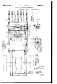
In the drawings 2- Figure 1 is a view in side elevation of the mechanism embodying the present invention showing the same applied.
Figure 2 is a view in plan of the frame structure and scoop of the mechanism, parts being in section.
Figure 3 is a view in front elevation of the upright structure carried by the tractor, the scoop carrying frame being in cross-section.
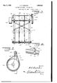
Figure -l is a view in rear elevation of the scoop.
Figure 5 is; an enlarged longitudinal section of the rear of the scoop looking toward the adjacent latch showing the latch engaged.
Figure 6 is a detailed top plan view of a latch and shove plate.
Figure 7 is an enlarged sectional view taken transversely of the side of the frame adjacent a latch and looking toward the latter.
Figure 8 is a view in side elevation of a latch and shove plate showing the latch retracted.
Figure 9 is a view in side elevation of the brake drum.
Referring more particularly to the drawings wherein like numerals of reference indicate corresponding parts throughout the several views, the numeral 1 indicates genorally a tractor on which the present invention is shown mounted. In the particular make of tractor to which the present scoop .fork is adapted to be connected there is mounted at the rear a draw bar 2 which is in a lower plane than the main frame or chassis 3 of the machine. This draw bar 2 has connected thereto a pair of forwardly extending beams 4 preferably of the charm 01 type, these beams being upon opposite sides of the machine and each connected at its forward end to a depending bracket 5 secured to the frame 3.
Extending forwardly from the beams 4 is a scoop fork carrying frame which consists of a pair of side channel beams 6 disposed upon opposite sides of the tractor like the beams 4. and each pivotally secured at its rear end as at 7 to a bracket The forward ends of these beams 6 of the fork frame are flattened as indicated by the numeral 8 and each has mounted thereon a bearing 9 in which is mounted one end of a rock shaft 10,
this shaft, of course, connecting the forward ends of these b ams together.
Adjacent the forward ends of the beams 6 a pair or more of cross brace bars 11 are mounted to give rigidity to this frame. The brace bars 11 which connect the beams 6 are centrally cohrfected-together bya pair of rcarwardly converging bars 12.
Extending across between and supported by the beams 6 between the bars 11 is a, shaft I 13 upon which is mounted adjacent each end a latch 14 which secures the fork, hereinafter described, in working position upon its supporting frame. These latches, as shown, are mountedintermediate their. ends and each is formed at its upper end to provide a bill 15 while at its lowcrend there is connected one elder a spring'lti wh ch has its other end 'attfit-lied'tO the adjacent beam. These springs lomaintain the latches in the proper vertical position.
ion'e of the bars 12 is a relatively long latch tripping bar 18'. one end of which is disposed adjacent one of the latches l4 and is connected thereto by an adjustable. link 19,whi1e the other end is" disposed adjacent the opposite side of the frame and has connected thereto a pull rod 20 which runs rearwardly along the inner side of the adjacent'beam' to a point adjacent the pivotal mounting of the beam where it connectswith a'crank fin-' ger21. pivotally mounted on the beam in the manner shown. This crank finger 'has op- 8B er'atively connected therewith a lever 22 which extends upwardly to a position where it'may be easily reached by an occupant of the tractor so that by oscillation of the lever reciprocation of the pull rod 20 may .be effected. I
"Pivotally mounted intermediate its ends upon'theoth'er one of the bars 12 is an auxiliary latchtrip fbar 23, one end of which is slid ably an'dpiv'otally attached to the bar 18 5 substant ally inidway between its ends as indicated at 24 while the other end is connected by the adjustable link 25, with the other latch 14. v
Mounted upon each of the beams 6 adjacent a latcl'rlt is a shove plate 26. which has in the forward edge thereof a notch or recess 27 which coacts with the bill of the adjacent latch as will be hereinafter more fully described.
"fPiyotally mounted at the point 17 upon 32 which connect it with the adjacent side tines 30.
As shown, the pivot about which the fork rotates, or in other words the rock shaft 10, is disposed a substantial distance rearwardly of the transverse center of the fork so that when'the fork;, is,-loaded the weight thereon would cause'it to pitch forwardly if the rear edge were not held down. The rear edge of the fork is normally helddown so as to maintain the bottom of the fork in a horizontal plane substantially parallel with the plane in which the beams. 6 lie by the latches 16, the bills of which hook over the rear edge of the plate 29 which forms the bottom of the fork.
It will be seen that when the fork is in normal horizontal position the plate29 will rest 'uponithe bottom edge of each of the notches 27 in-a shove plate 26 and will also bear against the vertical edges of these notches;
Pivotally attached to each side of the scoop fork 28 is an eye 33 throu 'h which passes a rod 34; The upper end of this rod has attached thereto a collar held in place by a nut 35 and surrounding the rod between the collar and nut 35 and the eye 33 is a coil spring 36. The other end of each rod 34 is pivotal ly attached to the adjacent end of the shaft 13 on which the latches 14 are pivotally mounted.
Disposed rearwardly of'the shaft 13 is a second shaft which is indicated by the numeral 37, this shafthaving its ends mounted in bearings carried by the beams 6. Mounted on the shaft'37 isa pair of pulleys each of which is indicated by the numeral 38.
The forward end of the tractor frame 3 has secured thereto a pair of upright beams each of which is indicated by the numeral 39, these beams being placed one adjacent each side of thetractor. At their lower ends the beams 39'are offset slightly as indicated at 40 so that the terminal lower portions will not be in a position to interfere with the turning of the steering wheels of-the tractor. These beams 39 are disposed within the scoop fork carrying frame as :shown in Figure 2,the beams 6 being in frictional engagement with the beams 39 so-that as the scoop fork frame is raised it willbe maintained in a vertical path by these upright beams.
Adjacent their upper ends the scoop fork frame guiding beams 39 have mounted on their forward faces bearings' ll in which is supported a. transversely extending shaft 42, the ends of which project beyond the beams 39. as shown in Figure-3. This shaft 42-carries on one end a belt drum or pulley 43 and upon its other end a brake drum 44. The pulley 43 iscon'nected by means of a belt 45 with the'power take-off pulley 46 of thetractor. Above the shaft 42 a brakeshaft 47 is mounted between the beams 39, one end of the shaft carrying a pair of fingers 48 to which are attached the ends of a brake band 49 which surrounds the drum 44 while the other end of this shaft carries a lever arm 50 to which is attached one end of apull rod 51 having its other end attached to a control lever 52 pivotally mounted adjacent the rear of the tractor.
Upon the shaft 42 there is mounted in spaced relation a pair of collars 53 and the shaft 42 has attached thereto the ends of a pair of cables 54 which pass downwardly about the pulleys 38 and back up to the brake shaft 47 "to which they are attached as indicated at 55. The ends of the cables 54 which are attached to the shaft 42 are wound up on this shaft in the operation of the mechanism and the collars 53 serve to keep the cables separated.
In the operation of the present scoop fork the fork is lowered to the ground while being held down on the beams 6 by the latches 14, as shown in Figure 1, the curved forward ends of the tines lying upon the surface of the ground. The tractor is then moved forward so that the points of the tines are forced under the material to be lifted.
. By manipulation of the proper controls upon the tractor power is then transmitted to the pulley 43 which rotates the shaft 42 and winds up the cables 54 thereon thus lifting the forward ends of thebeams 6 and the scoop shovel and other mechanism mounted thereon. During the movement of the tractor when the fork is being pushed into the material which is to be transported the plates 26 will receive any strain which might otherwise be applied to the latches 14, particularly if there should be any looseness in the I bearing 9. At the same time the rearward thrust of the beams 6 is carried entirely by the draft bar 2 which is attached to the rear of the tractor instead of by the brackets 5 and the frame 3 to which these brackets are attached.
After the load has been lifted to the desired elevation and transported to the place where it is to be dumped, the dumping is effected by pulling the rod to cause the oscillation of the latches 14 in the manner previously described. The load then overbalances the scoop fork so that the latter tips forwardly to allow the load to slip therefrom. When the scoop fork is tipped under the weight of the load the rear end swings up and causes compression of the spring 36 between the eye 33 carried by the scoop and the members 35 at the free end of the rod 34 so that as soon as the load leaves the scoop the spring 36 will react to throw the rear of the scoop downwardly again and cause it to be engaged by the latches 14 to be held in proper position thereby for the reception of another load.
After the scoop has been lifted from the ground by the lifting mechanism it may be held in' elevated'position so as to permit stopping of the drive belt 45, by-the brake band 49. As will be readily seen this is accom- The band thus holds the shaft 42 against roe,
tation and will not permit the unwinding of the cables 54 therefrom.
From the foregoing description it will be readily seen that the tractor attachment 'embodying the present invention is of relatively simple design and maybe inexpensively constructed. It will also be seen that its use will impose no strain upon the frame structure of the tractor to which it is attached as all of the strain of pushing the scoop into a pile of material is borne by the pull bar at the back of the tractor which is designed to stand such strains.
. Having thus described my invention, what I claimis 1. In an attachment of the character described for tractors, a frame designed to enclose the forward end of a tractor and project forwardly thereof, means for pivotally at-- rearwardly against, and when the scoop is engaged by, the latches.
2. In an attachment of the character described for tractors, including a frame designed to be pivotally attached at one end to the tractor with the opposite end projecting beyond the front thereof and means for raising the same; a rock shaft carried upon the front end of said frame, a scoop mounted upon said rock shaft, said frame including a pair of side beams, a second shaft extending transversely of the frame between said side beams, a pair of latch elements carried by said second shaft and designed to engage said scoop to maintain it in upright position on the frame, a relatively long bar pivotally mounted intermediate its ends on said frame and having adjustable connection at one end with one of said latches, a shorter bar pivotally mounted intermediate its ends upon said frame and having sliding pivotal connection with said first mentioned bar, the other end of said shorter bar having adjustable connection-with the other latch member, and a control rod connected at one end to the other end of said first mentioned bar.
3. In an attachment of the character described for tractors, a vertically swinging structure designed to have pivotal connection 4 names:
with the tractor, ascoop oscillatably mounted upon said structure, said scoop being arranged to-itip under the action of gravity, latch elements normally maintaining the .4 scoop against tipping, means for-raising the structure, and'means for automat1call returning said scoop .to latch engaged position after a tipping operation, comprisin a barhaving pivotal connection with sai structure, apivotally mountedeye carried lbythe scoop and having said bar extendin there- .t hrou'gh,'-an element carried by saicfcbar at its free endfand a coil spring surrounding .lwthe ,barbetween said eye andosaid element,
said spring being placed under compression when the scoop is tipped for a dumping operation. I
4. In a scooping attachment of the character described including a vertically movable frame structure, a fork pivotally mountedv upon said frame :and including .a. transverse rear member, a pair of latching elements pivotally mounted upon the frame 1.; rearwardly of the fork and'adapted to engage, the transverse member thereof, a pair of levers pivotally mounted intermediate their ends for-oscillation in the same plane beneath the fork, one of said levers being of v greater'length than the other, the lever of v reatest length having one end of the other everpivotally attached thereto 'substantial- \l'y midway between its ends, a connection bevtween the other end of the shorter lever and one end of the longer lever and said latch 85 members, and an actuating element connected with the other end of'the longer lever Whereby the oscillation of the longer lever will effeet the shifting of the'latches for the release of the fork; I p 40 In testimony whereof I hereunto afiix my signature.
ALBERT G. (JrlTISTER-v
Priority Applications (1)
| Application Number | Priority Date | Filing Date | Title |
|---|---|---|---|
| US474866A US1856629A (en) | 1930-08-12 | 1930-08-12 | Scooping attachment for tractors |
Applications Claiming Priority (1)
| Application Number | Priority Date | Filing Date | Title |
|---|---|---|---|
| US474866A US1856629A (en) | 1930-08-12 | 1930-08-12 | Scooping attachment for tractors |
Publications (1)
| Publication Number | Publication Date |
|---|---|
| US1856629A true US1856629A (en) | 1932-05-03 |
Family
ID=23885257
Family Applications (1)
| Application Number | Title | Priority Date | Filing Date |
|---|---|---|---|
| US474866A Expired - Lifetime US1856629A (en) | 1930-08-12 | 1930-08-12 | Scooping attachment for tractors |
Country Status (1)
| Country | Link |
|---|---|
| US (1) | US1856629A (en) |
Cited By (3)
| Publication number | Priority date | Publication date | Assignee | Title |
|---|---|---|---|---|
| US2429890A (en) * | 1945-07-09 | 1947-10-28 | Mcenglevan Heat Treating And M | Material loader |
| US2655277A (en) * | 1951-01-15 | 1953-10-13 | Florian J Gebauer | Rake attachment for tractors |
| US2979839A (en) * | 1959-08-17 | 1961-04-18 | Norbert J Hugger | Tool support for tractor |
-
1930
- 1930-08-12 US US474866A patent/US1856629A/en not_active Expired - Lifetime
Cited By (3)
| Publication number | Priority date | Publication date | Assignee | Title |
|---|---|---|---|---|
| US2429890A (en) * | 1945-07-09 | 1947-10-28 | Mcenglevan Heat Treating And M | Material loader |
| US2655277A (en) * | 1951-01-15 | 1953-10-13 | Florian J Gebauer | Rake attachment for tractors |
| US2979839A (en) * | 1959-08-17 | 1961-04-18 | Norbert J Hugger | Tool support for tractor |
Similar Documents
| Publication | Publication Date | Title |
|---|---|---|
| US2906077A (en) | Agricultural implement | |
| US2398119A (en) | Load handling attachment for tractors | |
| US1856629A (en) | Scooping attachment for tractors | |
| US2427575A (en) | Manure loader | |
| US2446827A (en) | Scoop and trip mechanism therefor | |
| US2628730A (en) | Loading attachment for tractors | |
| US2799129A (en) | Bale dropper attachment for hay balers | |
| US2523263A (en) | Stone digger | |
| US2731161A (en) | Fork attachment for tractors | |
| US2469187A (en) | Power digger and loader | |
| US1725201A (en) | Loading attachment for tractors | |
| US1628725A (en) | Stacker | |
| US948006A (en) | Shock and hay loader. | |
| US1715198A (en) | Potato digger | |
| US1935841A (en) | Cotton seed hull fork | |
| US1692468A (en) | Potato digger | |
| US1677490A (en) | Bagging platform and carrier attachment for harvester thrashers | |
| US2488061A (en) | Lock for hay rakes | |
| US3170584A (en) | Automatic self bunching and dispensing bale carrier | |
| US2427971A (en) | Loading machine | |
| US2273970A (en) | Combination hay buck and stacker | |
| US1222299A (en) | Traction-plow. | |
| US1365392A (en) | Hay-loader | |
| US1871599A (en) | Manure loader | |
| US2528045A (en) | Hayrack |