US1856626A - Multiple break oil switch for large currents - Google Patents
Multiple break oil switch for large currents Download PDFInfo
- Publication number
- US1856626A US1856626A US291929A US29192928A US1856626A US 1856626 A US1856626 A US 1856626A US 291929 A US291929 A US 291929A US 29192928 A US29192928 A US 29192928A US 1856626 A US1856626 A US 1856626A
- Authority
- US
- United States
- Prior art keywords
- contacts
- oil
- switch
- main
- main contacts
- Prior art date
- Legal status (The legal status is an assumption and is not a legal conclusion. Google has not performed a legal analysis and makes no representation as to the accuracy of the status listed.)
- Expired - Lifetime
Links
Images
Classifications
-
- H—ELECTRICITY
- H01—ELECTRIC ELEMENTS
- H01H—ELECTRIC SWITCHES; RELAYS; SELECTORS; EMERGENCY PROTECTIVE DEVICES
- H01H33/00—High-tension or heavy-current switches with arc-extinguishing or arc-preventing means
- H01H33/02—Details
- H01H33/04—Means for extinguishing or preventing arc between current-carrying parts
- H01H33/12—Auxiliary contacts on to which the arc is transferred from the main contacts
Definitions
- Our invention has been developed from the above point of view and according to it our improved oil switch for large currents is divided into a high capacity oil switch with an air cushion over the level of the oil, in which are located the rupturing contacts and an oil switch with a second oil tank, which houses the main contacts.
- a high capacity oil switch with an air cushion over the level of the oil, in which are located the rupturing contacts and an oil switch with a second oil tank, which houses the main contacts.
- the oil switch for the main contacts may be carried out as an oil switch for smaller interrupting capacities, inasmuch as the highest value which it has to break is the product of the loop voltage multiplied by a portion of the total current traversing the switch.
- the oil tank mounted on the cover of the high capacity switch for instance, which contains the main contacts and their circuits, may be constructed by comparatively thin, if desired, non-magnetic materials, such as sheet brass.
- a thin sheet of brass or a layer of an insulating textile material may be used, because according to our invention this cover does not serve its-supporting member for the leading-in insulators and these may be mount-ed on the bushings of the high capacity switch.
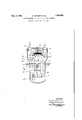
- FIG. 1 An embodiment of our invention is illustrated in the drawing afiixed hereto and-
- the leading-in insulators 17 are supported by the aid of the resilient main contacts 14 by means of the insulating bushings 18 in the cover 13 of the high capacity switch.
- the cover 16 thus only contains passage openings for the leading-in insulators 17.
- the oil tank 15 is preferably located on top of the cover 13 of the high capacity oil switch, so that it need not be provided with a bottom.
- the operation of the cross-bar 20 connecting the contacts 11 takes place in the usual man ner by means of a crank 21 mounted upon a shaft 22 passing through the wall of the tank 12. At the outside of the oil switch there is mounted upon the shaft 22 another crank '46 from which a connecting rod 24 passes above the cover 16 and by means of another rod 25 operates the movable main contact brush 14.
- the open position of the switch is shown in dotted lines.
- a multiple-break oil switch for large currents, in combination, a high capacity oil tank containing a pair of rupturing contacts and means for making a connection therebetween, an air cushion above the level of the oil in said tank, a separate oil tank for the main contacts of said switch disposed external of said high capacity oil tank, and an operating shaft adapted to open and close said rupturing contacts and said main contacts.
- a multiple-break oil switch for large currents, in combination, a high capacity oil tank containing the rupturing contacts of said switch, an air cushion above the level of the oil in said tank, a separate oil tank for the main contacts of said switch, which is arranged above said high capacity tank and the bottom of which is formed by the cover of the high capacity tank, and an operating shaft adapted to open and close said rupturing contacts and said main contacts.
- a high capacity oil tank containing the rupturing contacts or" said switch, an air cushion above the level of the oil in said tank, a separate oil tank for the main contacts of said switch, which is arranged above said high capacity tank and the bottom of which is form-ed by the cover of the high capacity tank, insulating bushes in the cover of said high capacity switch on which are arranged the leading-in insulators and the stationary main contacts, and an operating shaft adapted to open and close said contacts.
Landscapes
- Contacts (AREA)
Description
May 3, 1932. w. ESTORFF ET AL v MULTIYLE BREAK OIL SWITCH FOR LARGE CURRENTS Original Filed July 11, 1928 INVENTGRS Wa/fher Esforff X Ludw g He/nemeyer 7 ATT'ORNEY Patented May 3, 1932 UNITED STATES PATENT OFFECE WALTHER ESTOR-FF, OF BERLIN-CHARLOTTENBURG, AND LUDWIG- HEINEMEYER, OF BERLIN-LIGHTERFELDE, GERMANY, ASSIGNORS T0 WESTINGHOUSE ELECTRIC AND MANUFACTURING COIJIPANY, A CORPORATION OF PENNSYLVANIA MULTIPLE BREAK OIL SWITCH FOR LARGE CUBRENTS Our invention relates to improvements in multiple break oil switches for large currents.
The manufacture of oil switches for corn trolling currents of several thousand amperes becomes somewhat difiicult, because the magnetic fields of the strong currents demand the employment of non-magnetic materials, so
that the oil switch becomes rather expensive.
This is particularly the case as regards the cover of the oil switch, which for such large currents can no longer be constructed of iron or cast steel, but had to be made of manganese steel or bronze. It has therefore already been proposed to place the rupturing contacts of the switch under oil only, and leave the main contacts or their circuit above the oil, in order to eliminate the difiiculties, which arise from the passing of such high currents through the cover and thus to allow the employment of cheap materials in the container for the oil. This has, however, the great disadvantage, that the loop, which is formed by the circuit containing the ruptur ing contacts of the oil switch, may in the event of high short-circuit current intensities show such a high inductive voltage drop, that it reaches under certain circumstances the magnitude of the electric arc voltage.
This happens particularly then when more than two breaking points are provided. In such a case the arc remains stationary at the main contacts and the arc breakers, which protect the main brush against burning are subjected to a considerable amount of sparking and consequent wear. The incandescent copper particles are then blown about under the action of the strong magnetic field and are liable to cause flashovers over long distances.
Our invention has been developed from the above point of view and according to it our improved oil switch for large currents is divided into a high capacity oil switch with an air cushion over the level of the oil, in which are located the rupturing contacts and an oil switch with a second oil tank, which houses the main contacts. In this way the advantage is obtained, that by the immersion of the main contacts in oil backfiring at the main contacts is avoided, even when the arc- Application filed July 11, 1928,'Seria1 No. 291,929, and in Germany July 12, 1927. Renewed April 21, 1930.
ing voltage has been reached due to the inductive voltage drop of the loop. The oil insulation permits, furthermore, a closer spacing of the current carrying parts.
The oil switch for the main contacts may be carried out as an oil switch for smaller interrupting capacities, inasmuch as the highest value which it has to break is the product of the loop voltage multiplied by a portion of the total current traversing the switch. For this reason the oil tank mounted on the cover of the high capacity switch, for instance, which contains the main contacts and their circuits, may be constructed by comparatively thin, if desired, non-magnetic materials, such as sheet brass. For closing the oil tank either a thin sheet of brass or a layer of an insulating textile material may be used, because according to our invention this cover does not serve its-supporting member for the leading-in insulators and these may be mount-ed on the bushings of the high capacity switch.
An embodiment of our invention is illustrated in the drawing afiixed hereto and- The leading-in insulators 17 are supported by the aid of the resilient main contacts 14 by means of the insulating bushings 18 in the cover 13 of the high capacity switch. The cover 16 thus only contains passage openings for the leading-in insulators 17. For the main contacts 1 1 there are also provided renewable burning tips 19, which are resiliently mounted on the main contact 14. The oil tank 15 is preferably located on top of the cover 13 of the high capacity oil switch, so that it need not be provided with a bottom. The operation of the cross-bar 20 connecting the contacts 11 takes place in the usual man ner by means of a crank 21 mounted upon a shaft 22 passing through the wall of the tank 12. At the outside of the oil switch there is mounted upon the shaft 22 another crank '46 from which a connecting rod 24 passes above the cover 16 and by means of another rod 25 operates the movable main contact brush 14. The open position of the switch is shown in dotted lines.
Various chan es and modifications may be made without departing from the spirit of our invention and the ambit of our claims.
We claim as our invention:
1. In a multiple-break oil switch for large currents, in combination, a high capacity oil tank containing a pair of rupturing contacts and means for making a connection therebetween, an air cushion above the level of the oil in said tank, a separate oil tank for the main contacts of said switch disposed external of said high capacity oil tank, and an operating shaft adapted to open and close said rupturing contacts and said main contacts.
2. In a multiple-break oil switch for large currents, in combination, a high capacity oil tank containing the rupturing contacts of said switch, an air cushion above the level of the oil in said tank, a separate oil tank for the main contacts of said switch, which is arranged above said high capacity tank and the bottom of which is formed by the cover of the high capacity tank, and an operating shaft adapted to open and close said rupturing contacts and said main contacts.
3. Into multiple-break 'oil switch for large currents, in combination, a high capacity oil tank containing the rupturing contacts or" said switch, an air cushion above the level of the oil in said tank, a separate oil tank for the main contacts of said switch, which is arranged above said high capacity tank and the bottom of which is form-ed by the cover of the high capacity tank, insulating bushes in the cover of said high capacity switch on which are arranged the leading-in insulators and the stationary main contacts, and an operating shaft adapted to open and close said contacts.
4. The combination with separable main contact members enclosed in a chamber containing a quenching fluid, of separable secondary contact members associated with the first said members and enclosed in a chamber that is adjacent to the first said chamber and separated therefrom by an oil-tight wall which su ports the contacts in both chamhers, the rst-mentionedchamber being made of non-magnetic material and being external to the second-mentioned chamber.
5. Ina circuit interrupter,-a container for a pair of main contacts, a pai-r'of conductors extending through said container to said contacts, said container having a portion of nonmagnetic material surrounding said conductors, a second container enclosing a pair of rupturing contacts connected in parallel with said main contacts, and means for operating said main and rupturing contacts in sequence, the main contacts closing a circuit which does not enter the second container.
6. In a circuit interrupter, a container of light-weight non-magnetic material enclosing a pair of main contacts and a container of heavy-weight magnetic material enclosing a pair of rupturing contacts, and means for operating said main and said rupturin contacts in sequence, the main contacts closing a circuit which does not enter the second container.
7. In a circuit interrupter, a container for a pair of main contacts, a pair of conductors extending throu said container to said contacts, said container having a portion of nonmagnetic material surrounding said conductors, a second container enclosing a pair of rupturing contacts connected in parallel with said main contacts, the main contacts closing a circuit Which does not enter the second 00ntainer, and means for opening said-main and rupturing contacts in sequence, first the main contacts and then the rupturing contacts.
In testimony whereof we have hereunto subscribed our names this 26th day of June,
VVALTHER- ESTORFF. LUDWIG HEINEMEYER.
Applications Claiming Priority (1)
| Application Number | Priority Date | Filing Date | Title |
|---|---|---|---|
| DE1856626X | 1927-07-12 |
Publications (1)
| Publication Number | Publication Date |
|---|---|
| US1856626A true US1856626A (en) | 1932-05-03 |
Family
ID=7746258
Family Applications (1)
| Application Number | Title | Priority Date | Filing Date |
|---|---|---|---|
| US291929A Expired - Lifetime US1856626A (en) | 1927-07-12 | 1928-07-11 | Multiple break oil switch for large currents |
Country Status (1)
| Country | Link |
|---|---|
| US (1) | US1856626A (en) |
-
1928
- 1928-07-11 US US291929A patent/US1856626A/en not_active Expired - Lifetime
Similar Documents
| Publication | Publication Date | Title |
|---|---|---|
| US2100753A (en) | Circuit interrupter | |
| US2257900A (en) | Tube switch | |
| US2555799A (en) | Electric switch | |
| US1856626A (en) | Multiple break oil switch for large currents | |
| US4604507A (en) | Miniature circuit breaker with improved insulation level | |
| US1866495A (en) | Electric circuit breaker | |
| US1834856A (en) | Circuit breaker | |
| US2316470A (en) | Switch construction | |
| US2160630A (en) | Circuit breaker | |
| US1645905A (en) | Provements limited | |
| US999780A (en) | Electric fuse and fuse-holder. | |
| GB438401A (en) | Improvements in or relating to electric circuit interrupters | |
| US2025386A (en) | Electric circuit breaker | |
| US967280A (en) | Magnetic blow-out. | |
| US1596417A (en) | Circuit interrupter | |
| US1006504A (en) | Alternating-current switch. | |
| US1988927A (en) | Blow out coil | |
| US1825228A (en) | Electric switch and arc extinguishing method | |
| US2501323A (en) | Magnetic blowout circuit breaker | |
| US1623851A (en) | Circuit interrupter | |
| US1867293A (en) | Electric circuit breaker | |
| US2970196A (en) | Circuit interrupters | |
| US1483431A (en) | Control apparatus | |
| US1555299A (en) | Circuit interrupter | |
| US1862782A (en) | Electric switch or circuit breaker |