US1856618A - Heat exchanger - Google Patents
Heat exchanger Download PDFInfo
- Publication number
- US1856618A US1856618A US455035A US45503530A US1856618A US 1856618 A US1856618 A US 1856618A US 455035 A US455035 A US 455035A US 45503530 A US45503530 A US 45503530A US 1856618 A US1856618 A US 1856618A
- Authority
- US
- United States
- Prior art keywords
- tube
- sleeve
- sheet
- tubes
- aperture
- Prior art date
- Legal status (The legal status is an assumption and is not a legal conclusion. Google has not performed a legal analysis and makes no representation as to the accuracy of the status listed.)
- Expired - Lifetime
Links
- 239000002184 metal Substances 0.000 description 8
- 238000010276 construction Methods 0.000 description 6
- 239000007789 gas Substances 0.000 description 4
- 238000000034 method Methods 0.000 description 4
- 230000015572 biosynthetic process Effects 0.000 description 3
- 230000008602 contraction Effects 0.000 description 3
- 229910000831 Steel Inorganic materials 0.000 description 2
- 238000005219 brazing Methods 0.000 description 2
- 230000006835 compression Effects 0.000 description 2
- 238000007906 compression Methods 0.000 description 2
- 239000012809 cooling fluid Substances 0.000 description 2
- 238000003780 insertion Methods 0.000 description 2
- 230000037431 insertion Effects 0.000 description 2
- 238000005476 soldering Methods 0.000 description 2
- 239000010959 steel Substances 0.000 description 2
- 241000370685 Arge Species 0.000 description 1
- 238000001816 cooling Methods 0.000 description 1
- 238000006073 displacement reaction Methods 0.000 description 1
- 238000005553 drilling Methods 0.000 description 1
- 239000000945 filler Substances 0.000 description 1
- 239000001257 hydrogen Substances 0.000 description 1
- 229910052739 hydrogen Inorganic materials 0.000 description 1
- 125000004435 hydrogen atom Chemical class [H]* 0.000 description 1
- 238000007689 inspection Methods 0.000 description 1
- 239000007788 liquid Substances 0.000 description 1
- 238000012986 modification Methods 0.000 description 1
- 230000004048 modification Effects 0.000 description 1
- 238000005192 partition Methods 0.000 description 1
- 239000012858 resilient material Substances 0.000 description 1
- 230000008961 swelling Effects 0.000 description 1
- XLYOFNOQVPJJNP-UHFFFAOYSA-N water Substances O XLYOFNOQVPJJNP-UHFFFAOYSA-N 0.000 description 1
- 238000004804 winding Methods 0.000 description 1
Images

Classifications
-
- F—MECHANICAL ENGINEERING; LIGHTING; HEATING; WEAPONS; BLASTING
- F28—HEAT EXCHANGE IN GENERAL
- F28F—DETAILS OF HEAT-EXCHANGE AND HEAT-TRANSFER APPARATUS, OF GENERAL APPLICATION
- F28F9/00—Casings; Header boxes; Auxiliary supports for elements; Auxiliary members within casings
- F28F9/02—Header boxes; End plates
- F28F9/04—Arrangements for sealing elements into header boxes or end plates
- F28F9/16—Arrangements for sealing elements into header boxes or end plates by permanent joints, e.g. by rolling
- F28F9/165—Arrangements for sealing elements into header boxes or end plates by permanent joints, e.g. by rolling by using additional preformed parts, e.g. sleeves, gaskets
-
- Y—GENERAL TAGGING OF NEW TECHNOLOGICAL DEVELOPMENTS; GENERAL TAGGING OF CROSS-SECTIONAL TECHNOLOGIES SPANNING OVER SEVERAL SECTIONS OF THE IPC; TECHNICAL SUBJECTS COVERED BY FORMER USPC CROSS-REFERENCE ART COLLECTIONS [XRACs] AND DIGESTS
- Y10—TECHNICAL SUBJECTS COVERED BY FORMER USPC
- Y10T—TECHNICAL SUBJECTS COVERED BY FORMER US CLASSIFICATION
- Y10T29/00—Metal working
- Y10T29/49—Method of mechanical manufacture
- Y10T29/4935—Heat exchanger or boiler making
- Y10T29/49373—Tube joint and tube plate structure
-
- Y—GENERAL TAGGING OF NEW TECHNOLOGICAL DEVELOPMENTS; GENERAL TAGGING OF CROSS-SECTIONAL TECHNOLOGIES SPANNING OVER SEVERAL SECTIONS OF THE IPC; TECHNICAL SUBJECTS COVERED BY FORMER USPC CROSS-REFERENCE ART COLLECTIONS [XRACs] AND DIGESTS
- Y10—TECHNICAL SUBJECTS COVERED BY FORMER USPC
- Y10T—TECHNICAL SUBJECTS COVERED BY FORMER US CLASSIFICATION
- Y10T29/00—Metal working
- Y10T29/49—Method of mechanical manufacture
- Y10T29/4935—Heat exchanger or boiler making
- Y10T29/49377—Tube with heat transfer means
- Y10T29/49378—Finned tube
Definitions
- This invention relates chiefly to heat exchangers of the type'in which a bundle of tubes is supported between tube sheets and surrounded by a suitable casing.
- the inven tion concerns more particularly heat exchangers of this type in which the tubes are provided with external fins or the like, for the purpose of increasing the heat transferring surface of the tubes.
- heat exchangers are used largely in transferring heat from a liquid, usually passed through the inside of the tubes, to a gas which is circulated over the outsides of the tubes.
- heat exchangers of this kind are employed in connection with the cooling of large electric generators.
- the exchanger When used for this purpose-the exchanger is connected in a duct system with the generator, and air or other gas, for example hydrogen, is circulated through this duct system, the gas being heated during its passage through the generator, thereby removing heat from the generator, and thegas being cooled in passing through the heat exchanger.
- an important object of the present invention is to provide a construction in which the individual tubes can be readily removed from, and replaced in the tube bundle without damage to the external fins which are ordinarily comparatively fragile and easily injured.
- Another object of the invention is to accomplish the object just referred to, and still preserve adequate strength in the tube sheets.
- a further object of the invention is to provide means for joining the tubes to the tube sheets in such a way as to effectively prevent leakage without greatly increasing the cost of making these joints over the cost of the ordinary plain expanded joint.
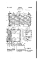
- Fig. 1 is a central vertical section through the heat exchanger.
- Fig. 2 is an end view looking from the right end of Fig. 1, but with parts broken away so as to show the tube sheet at the rear or left hand end as well as at the front or righthand end of the exchanger.
- Fig. 3 is an enlarged fragmentary horizontal section taken on line 3-3 of Fig. 2.
- Fig.4 is a still further enlarged section of the improved joint between the end of a tube and tube sheet.
- Fig. 5 is a view similar to Fig. 4 of a modified form of joint.
- Fig. 6 is an enlarged longitudinal section through a single tube and a portion of a tube sheet showing a somewhat simpler form of the improved tube and tube sheet joint.
- Fig. 7 is a similar view of another modified form of joint.
- Fig. 8 is a similar view of the simplified form of joint shown in Fig. 6 shown in connection with a tube having an oval cross section at its central portion;
- Fig. 9 is a cross sectional view of the tube shown in Fig. 8:
- the tube bundle 10 is supported by the tube sheets 11 and 12, respectively, the tube bundle consisting of a relatively arge number of closely spaced fin tubes l3.
- the tube sheets Hand 12 are supported upon the ends of the casing of the heat exchanger, which consists of the steel shapes or sections 14, and sheet metal plates 15 at both the'near and far sides of the exchanger, as viewed in Fig. l.
- the air ducts connecting the exchanger with the generator are joined tothe casing at the top and bottom, respectively, so that the air or gas passes vertically through the tube bundle.
- a head 16 is bolted around the rectangular periphery of the tube sheet 11, and a similar head 17 is similarly bolted to the opposite tube sheet- 12.
- the head 16 is provided with a flange inlet 18 and a flange outlet 19 for the water or other cooling fluid.
- the heat exchanger illustrated is a so-called four-pass exchanger.
- the tubes 13 are of uniform cross section throughout their length, and are provided throughout their central portions and extending for substantially the entire distance between the tube sheets 11 and 12, with metallic fins 22.
- These fins 22 are preferable arranged in equally spaced relation, and are secured upon the outside surfaces of the tubes in good heat exchanging relation with the metal of the tubes so that heat may pass readily by conduction between the fins and the walls of the tubes.
- These fins are preferably of helical form and applied to the tubes by grooving the same and winding a metal ribbon into the groove, and then upsetting the metal of the tube against the base. of the helical fin. This method of applying the fins produces a joint between fin and tube of excellent heat conductivity.
- other methods of applying the fins may be employed.
- helical fins may be secured to the surface of the tube by soldering or brazing, or the fins may be applied as individual annular discs secured to the tube in spaced relation by. soldering, brazing, or in any other suitable manner.
- a hole 23 is punched in one of the tube sheets, say for example, tube sheet 12, of slightly larger diameter than the diameter of the fins 22, so that the tube with the fins thereon will slide readily through this aperture.
- a sleeve or thimble 24 surrounds the end of the tube and fills the annular space between the tube and the walls of hole 23, the sleeve being of substantially the same annular thickness as the width of the fins 22.
- Sleeve 24 is expanded in any suitable manner so that its exterior surface is forced into intimate contact with the contiguous surface of hole 23.
- the tube isalso similarly expanded into intimate contact with the interior surface of sleeve 24.
- sufiiciently tight joints are formed in the manner just descr bed and which is illustrated in Fig. 6.
- annular groove 25 see. Figs 3, 4 and 5
- a similar'groove 26 is formed in the interior wall of sleeve 24. Then in expanding the sleeve 24 into the hole 23 by means of a suitable expanding tool,
- a rib 27 is formed on the surface of sleeve 24 which projects into and fills the annular groove or recess 25.
- the expanding tool forms a rib 28 on the outside. of the tube which projects into and lills recess 26.
- the rib and groove construction just described facilitates the making of tight joints between the tube and the sleeve and between the sleeve and the tube sheet.
- the ordinary use of the expanding tool in the'hands of the ordinary workman will produce a-much larger percentage of tight joints when the rib and groove construction is used than when the ribs and grooves are omitted and the surfaces are left smooth.
- the ribs and grooves preferably have approximately straight radial Walls.
- each tube of the tube bundle 10 is secured in its tube sheet in the usual manner by expanding the tube into a tube hole of customary size which is only slightly larger than the diameter of the tube.
- the tube sheets 11 and 12 are each punched with alternate large and small tube receiving holes so that alternate tubes are secured in the tube sheet by means of the improved form of joint above described, and the intermediate tubes are expanded into holes of ordinary size in the-usual manner.
- Fig. 3 is a section taken centrally through the first three tubes at the'left hand end of the uppermdst row of tubes shown in Fig. 2. It will be' seen that two of these tubes are secured in tube sheet 12 by means of the improved form of joint, and the intermediate tube passes through a tube aperture of substantially the same size as the tube and into which it has been expanded.
- the procedure in removing and inserting a faulty tube is as follows.
- the caps or heads 16 and 17 are first removed from the heat exchanger so as to expose the tube sheets 11 and 12.
- the faulty tube is located, and its sleeve 24 together with the end of the tube are drilled away following the same procedure as would be followed in removing a tube which had been expanded into a tube hole in the ordinary manner.
- the only clifference is that there is more metal to be drilled away, and for this reason and also to metal.
- the new finned tube is passed through the 7 hole 23 until its inner end is received in the tube sheet having the small tube hole, and
- a plurality ofconcent'ric sleeves are used in place of a' single sleeve.
- two concentric sleeve 37 and 38 are employed, sleeve 37- being expanded into the hole in the tube sheet first, and the .inner sleeve 38 then expanded into the sleeve 37.
- the tube is, of course, ex-
- the construction shown in the lower part of Fig. 3 and at the left'hand'end of Fig. 1 is employed for the purpose of compensating for the longitudinal expansion and, contraction of the tubes 13.
- thecaps 17 are bolted to the tube sheet 12, but the tubes are not secured fast to the heat exchanger casing, but are mounted in such a Way as to permit the cap and tube sheet to move closer to or further away from the end of the casing as the tubes contract or expand.
- the end of the casing has a relatively wide face 32 formed by a part of the steel angle 14 of the framework, and a groove 33 is formed near the periphery-of the inner face of the tube sheet 12.
- a gasket 34" of resilient material such as rubber, is placed between the inner face of a tube sheet, and face 32 of the end of thecasing, and isretained in position by the groove 33.
- This resilient gasket is placed under an initial compression so as to deform it from its original natural conformation.
- the cross section of the gasket shown in Fig. 3 and Fig. 1 before assembling is round, and it is compressed to approximately the shape shown in these figures when the apparatus is assembled. Any further contraction of the tubes compresses the gasket still more, and when the tubes are elongated by expansion so that the tube sheet moves further and prevent leakage from the interior of the casing.
- tube sheet 12 with respect to the end face 32 of the casing is such that a very considerable initial compression is imparted to gasket 34, and the resiliency of the gasket is sufficient to take care of the maximum amount of movement of the tube sheet either'towardor away from the casing caused by contraction or expansion of the tubes 13.
- a plurality of guide studs 36 are employed, two of which are shown in Fig. 1. These guide studs are tapped into tube sheet 12 from its inner face, and project through apertures in the face-32 of the casing. The studs 36 are received in these apertures with a sliding fit and thereby Fig. 1 are slightly larger than the fins so that the finned tubes may be easily passed through them. As the support given to each of the tubes by this perforated plate is imparted directly to the edges of the fins, the plate is made relatively thick so that it will span a plurality of fins.
- the sleeve 39 is the annular filler sleeve shown in the previous figures of the drawings recessed at its outer end and provided with a longitudinal extension 40 at'its inner end.
- the recess at the outer end of the sleeve reduces the thickness of the annular portion 41 of the sleeve within the tube sheet aperture 42 so that it is easier to expand the sleeve into the tube sheet.
- the extension 40 on the inner side of the sleeve is providediwith a tube receiving aperture 43 of a diameter corresponding to that of the tube so that the tube may be expanded into this aperture in the same manner as the tube would be expanded directly into an ordinary tube sheet aperture.
- the joint between the'tube and aperture 43, and the oint between the sleeve 39 and aperture 42 may be plain joints. It is desirable under most conditions to employ the rib and groove form of joint previously described. Thus a single relatively large rib and grooves 44 are shown in Fig. 7 between the annular recessed portion 41 and aperture 42 of the tube sheet. Between the tubeand the aperture 43 ofthe sleeve, it isdesirable to employ a multiple rib and groove structure in which each individual rib and groove is relatively small. In this way the forces applied during the formation of the rib by the expanding tool are reduced so as to prevent deformation of the extension 40 which, because it projects beyond the surface of the tube sheet, is unsupported thereby.
- rib and groove joints 45 and 46 are shown.
- the riband groove 45 are located within the aperture 42 of the tube sheet so that if there is any swelling or enlargement of the sleeve 39 during their. formation, this merely tends to improve the tightness of the joint between the sleeve and aperture 42.
- the rib and groove 46 are located entirely within the extension 40.
- the diameter of the longitudinal extension 40 is preferably made the same as the diameter of the fins 22 which is substantially equal to the diameter of the tube aperture 42 but just enough smaller than this aperture to enable the fins to slide readily therethrough.
- tube 47 is of flattened or elliptical cross section as shown in Fig. 9 and may be smooth or it may be provided with fins at least upon its flattened s1des. The width of the flattened said ofi'set portion.
- tube is such as to just slide through the tube aperture 48 in the tube sheet, and the end of the tube, which is circular, is expanded into a plain sleeve '49 which is similar to the sleeve illustrated in Fig.6.
- Sleeve 49 is expanded into the aperture in the tube sheet.
- the rib and groove joints previously described niay be used, or the form of sleeve described in connection with Fig. 7 may also be employed.
- a 'tube having outwardly' projecting fins on its central portion for increasing the heat transmitting surface of the tube, a tube sheet for supporting one end of said tube and having a tube aperture slightly larger than theoutside dimension of the fins so that the said finned tube can be removed from the exchanger through said aperture, a sleeve within said aperture surrounding the end of the tube, a coacting rib and groove on the sleeve and tube sheet re- I roove, the surfaces of the sleeve opposite I the rib and groove therein being smooth.
- a tube of uniform cross-section provided with outwardly projecting fins for increasing the heat transmitting surface of the tube, a tube sheet for supporting one end of said tube and having a tube aperture slightly larger than the outside diameter of the fins so that said finned tube can be removed from the exchanger through said aperture, and means for securing the end of the.
- tube in said tube aperture comprising-a sleeve within said aperture surrounding the end of the tube, a coacting rib and groove on the sleeve and tube sheet respectively,- and a similar coacting rib and groove on the tube-and sleeve'displ'aeed out of the plane of said first-mentioned rib and groove, the surfaces of the sleeve opposite the rib and groove therein being smooth.
- a tube having at its central portion means effecting an enlargement of the outside dimension of said central portion, a tube sheet for supporting one end of said tube and having a tube aperture slightly larger than said outsidedimensi'on, and means for securing the end of.
- said tube in said tube sheet comprising a sleeve having a recessed-portion at its outer end and an offset portion at its inner end, said recessed portion being expanded into vsaid tube sheet, and the end of said tube being expanded into central portion means efi'ecting an enlarge- Ell ment of the outside dimension of said central portion, a tube sheet for supporting one end of said tube and having a tube aperture slightly.
- means for securing the end of said tube in said tube sheet comprising a sleeve having an outer recessed portion and an inner olfset portion, the recess in said outer portion being larger in diameter than the end of said tube and being expanded into said tube aperture,
- said ofi'set portion extending inwardly be yond the inner surface of the tube sheet and.
- a tube of uniform cross-section provided with outwardly projecting fins for increasing the' heat transmittingsurface of the-tube, a tube sheet for supportlng one end of said tube and having a tube aperture slightly larger than the outside diameter of said fins so that said finned tube can be removed from the exchanger through said aperture, and means for securing the end ofthe tube in said aperture comprising a sleeve having a relatively thick annular wall surrounding the end of the tube and into which the end of the tube is expanded, and a portion having a relatively thin annular wall disposed outwardly from said thick walled portion and expanded into the tube aperture in the tube sheet. 6.
- a tube bundle containing tubes of uniform cross-sectionprovided with outwardly projecting fins for increasing the heat transmitting surface of the tubes a pair of tube sheets for supporting the said tubes at their ends, said tube sheets each having alternate large and small tube apertures therein, the large apertures in one sheet being in alignment with the small apertures in the opposite tube sheet and the large apertures being slightly larger than the fins so as to permit the removal of the said finned tubes therethrough, a sleeve expanded into each of said large apertures, means for connecting one end of a tube with each of said sleeves, and the opposite end of the tube being expanded into the small aperture in the opposite tube sheet.
- a tube having at its central portion means effecting an enlargement of the outside dimension of said central portion, a tube sheet for supporting one end of said tube and having a tube aperture slightly larger than said outside dimension. and means for securing the end of said tube in said tube sheet comprising a sleeve of greater length than the thickness of said tube sheet, said sleeve having a recess in its outer portion of less length than'the thickness of said tube sheet and of larger diameter than said tube, a coacting rib and groove respectively on the-outer surface of the sleeve and the wall of the tube aperture in the tube sheet, and a coacting rib and groove respectively on the outer surface of said tube and the inner wall of saidsleeve and located longitudinally between the outer and inner surfaces of said tube sheet.
- a tube having at its central portion means efiecting an enlargement of the outside dimension of said central portion, a tube sheet for supporting one end of said tube and having a-tubeaperture slightly larger than said outside dimension, and means for securing the end of said tube in said tube sheet comprising a sleeve the inner portion of which envelopes said tube and the outer portion of which extends beyond the end of the tube, said outer portion being secured to said tube sheet and the end of said tube being secured to said inner portion.
- a tube provided with means for increasing the heat transferring surface of the tube, a tube sheet for supporting one end of said'tube and having a tube aperture slightly larger than the outside diameter of said tube so that the same can be removed from the exchanger through said aperture, and means for securing the end of the tube in said aperture comprising a sleeve having a relatively thick annular wall surrounding the end of the tube and into which the end of the tube is expanded, and a portion having a relatively thin annular wall disposed outwardly from said thick walled portion and expanded into the tube aperture in the tube sheet.
- a tube bundle containing tubes provided with means for increasing the heat transferring surface of the tubes, a pair of tube sheets for supporting the said tubes at their ends, said tube sheets each having alternate large and small tube apertures therein, the large apertures in one sheet being in alignment with the small apertures in the opposite tube sheet and the large apertures being slightly larger than the tubes so as to permit the removal of the said tubes therethrough, a sleeve expanded into each of said large apertures.
- a tube having at its central portion means effecting an enlargement of the outside dimension of said central portion, a tube sheet for supporting one end of said tube and having a tube aperture slightly larger than said outside dimension, and means for securing the end of said tube in said tube sheet comprising a sleeve of greater length than the thickness of said tube sheet, said sleeve havinga recess in its outer portion of less length than the thickness of said tube sheet and of larger diameter than said tube, a eoaeting rib and groove respectively on the outer surface of the sleeve and the van of the tube aperture in the tube sheet,
- a tube having means eflecting an enlargement of the outside dimension of the central portion of the tube, atube sheet for supporting one end of the tube and having a tube aperture slightly larger than said outside dimension, and means for securing the end of said tube in said tube sheet comprising an outer sleeve expanded into said tube aperture and an inner sleeve expanded into said outer sleeve, the said tube being secured to said inner sleeve.
Landscapes
- Engineering & Computer Science (AREA)
- Physics & Mathematics (AREA)
- Thermal Sciences (AREA)
- Mechanical Engineering (AREA)
- General Engineering & Computer Science (AREA)
- Heat-Exchange Devices With Radiators And Conduit Assemblies (AREA)
Description
May3, 1932. V S'BROWN 1,856,618
HEAT E XC HANGER Filed May 23, 1930 2 Sheets-Sheet I M Fi .1
INVENTOR Siam/ y Brow/7 {a ATTORNEYS s. BROWN HEAT EXCHA GER May 3, 1932.
Filed May 2 3, 1930 .2 Sheets-Sheet a a wi BEN 6 R m mm A m5 m v v wk .m
n m M 5 W. M.
Patented May 3, 1932 STANLEY BROWNQ OF GARDEN CITY, NEW YORK,
COMPANY, OF NEW YORK, N.
ASSIGNOIRi-TO THE GRISCOM-RUSSELL Y., A CORPORATION or DELAWARE HEAT EXCHAN GER Application filed May 23,
This invention relates chiefly to heat exchangers of the type'in which a bundle of tubes is supported between tube sheets and surrounded by a suitable casing. The inven tion concerns more particularly heat exchangers of this type in which the tubes are provided with external fins or the like, for the purpose of increasing the heat transferring surface of the tubes.
Such heat exchangers are used largely in transferring heat from a liquid, usually passed through the inside of the tubes, to a gas which is circulated over the outsides of the tubes. Thus, for example, heat exchangers of this kind are employed in connection with the cooling of large electric generators. When used for this purpose-the exchanger is connected in a duct system with the generator, and air or other gas, for example hydrogen, is circulated through this duct system, the gas being heated during its passage through the generator, thereby removing heat from the generator, and thegas being cooled in passing through the heat exchanger.
In heat exchangers of this kind, it is sometimes desirous to remove individual tubes from the tube bundle for inspection or repair,
I and with the ordinary heat exchanger construction this is very laborious, if not impossible, because of the presence of the external fins upon the tubes. Accordingly, an important object of the present invention is to provide a construction in which the individual tubes can be readily removed from, and replaced in the tube bundle without damage to the external fins which are ordinarily comparatively fragile and easily injured.
Another object of the invention is to accomplish the object just referred to, and still preserve adequate strength in the tube sheets.
A further object of the invention is to provide means for joining the tubes to the tube sheets in such a way as to effectively prevent leakage without greatly increasing the cost of making these joints over the cost of the ordinary plain expanded joint.
The invention will be understood'from a consideration of the accompanying drawings, which, by way of example, illustrate the 1930. Serial No. 455,035.
invention as applied to a generator air cooler.
In these drawings, 4
Fig. 1 is a central vertical section through the heat exchanger.
Fig. 2 is an end view looking from the right end of Fig. 1, but with parts broken away so as to show the tube sheet at the rear or left hand end as well as at the front or righthand end of the exchanger.
Fig. 3 is an enlarged fragmentary horizontal section taken on line 3-3 of Fig. 2.
Fig.4 is a still further enlarged section of the improved joint between the end of a tube and tube sheet.
Fig. 5 is a view similar to Fig. 4 of a modified form of joint.
Fig. 6 is an enlarged longitudinal section through a single tube and a portion of a tube sheet showing a somewhat simpler form of the improved tube and tube sheet joint.
Fig. 7 is a similar view of another modified form of joint.
Fig. 8 is a similar view of the simplified form of joint shown in Fig. 6 shown in connection with a tube having an oval cross section at its central portion; and
Fig. 9 is a cross sectional view of the tube shown in Fig. 8:
Referring now to the accompanying drawings, the tube bundle 10 is supported by the tube sheets 11 and 12, respectively, the tube bundle consisting of a relatively arge number of closely spaced fin tubes l3. The tube sheets Hand 12 are supported upon the ends of the casing of the heat exchanger, which consists of the steel shapes or sections 14, and sheet metal plates 15 at both the'near and far sides of the exchanger, as viewed in Fig. l.
The air ducts connecting the exchanger with the generator are joined tothe casing at the top and bottom, respectively, so that the air or gas passes vertically through the tube bundle.
A head 16 is bolted around the rectangular periphery of the tube sheet 11, and a similar head 17 is similarly bolted to the opposite tube sheet- 12. The head 16 is provided with a flange inlet 18 and a flange outlet 19 for the water or other cooling fluid. The
The tubes 13 are of uniform cross section throughout their length, and are provided throughout their central portions and extending for substantially the entire distance between the tube sheets 11 and 12, with metallic fins 22. These fins 22 are preferable arranged in equally spaced relation, and are secured upon the outside surfaces of the tubes in good heat exchanging relation with the metal of the tubes so that heat may pass readily by conduction between the fins and the walls of the tubes. These fins are preferably of helical form and applied to the tubes by grooving the same and winding a metal ribbon into the groove, and then upsetting the metal of the tube against the base. of the helical fin. This method of applying the fins produces a joint between fin and tube of excellent heat conductivity. However, other methods of applying the fins may be employed. For example, helical fins may be secured to the surface of the tube by soldering or brazing, or the fins may be applied as individual annular discs secured to the tube in spaced relation by. soldering, brazing, or in any other suitable manner.
Referring now particularly to Figs. 3. 4, 5 and 6, the improved joint construction which I employ is as follows: A hole 23 is punched in one of the tube sheets, say for example, tube sheet 12, of slightly larger diameter than the diameter of the fins 22, so that the tube with the fins thereon will slide readily through this aperture. A sleeve or thimble 24 surrounds the end of the tube and fills the annular space between the tube and the walls of hole 23, the sleeve being of substantially the same annular thickness as the width of the fins 22. Sleeve 24 is expanded in any suitable manner so that its exterior surface is forced into intimate contact with the contiguous surface of hole 23. The tube isalso similarly expanded into intimate contact with the interior surface of sleeve 24.
For some uses of the heat exchanger, sufiiciently tight joints are formed in the manner just descr bed and which is illustrated in Fig. 6. However, in order to provide a joint that will withstand greater pressure and to enable the tubes 13 to withstand a greater longitudinal stress or thrust with respect to the tube sh eet, an annular groove 25 see. Figs 3, 4 and 5) is formed in the wall of hole 23 in the tube sheet, and a similar'groove 26 is formed in the interior wall of sleeve 24. Then in expanding the sleeve 24 into the hole 23 by means of a suitable expanding tool,
a rib 27 is formed on the surface of sleeve 24 which projects into and fills the annular groove or recess 25. Similarly in expanding the tube into the sleeve, the expanding tool forms a rib 28 on the outside. of the tube which projects into and lills recess 26. These two sets of ribs and grooves are preferably displaced from one another as shown, so that they will not lie in a common plane.
In addition to preventing longitudinal (lisplacemcnt of the tubes with respect to the tube sheet, the rib and groove construction just described facilitates the making of tight joints between the tube and the sleeve and between the sleeve and the tube sheet. In other words, the ordinary use of the expanding tool in the'hands of the ordinary workman will produce a-much larger percentage of tight joints when the rib and groove construction is used than when the ribs and grooves are omitted and the surfaces are left smooth. The ribs and grooves preferably have approximately straight radial Walls.
In expanding the sleeve into the tube sheet hole 23, a general displacement orfiowing of the metal of the sleeve takes place, in causing the formation of the rib 27, which reduces slightly the thickness of the sleeve. Similarly, when the tube is expanded into the sleeve, a very slight thinning of the wall of the tube takes place, as indicated at 29 in Fig. 4.
The opposite end of each tube of the tube bundle 10 is secured in its tube sheet in the usual manner by expanding the tube into a tube hole of customary size which is only slightly larger than the diameter of the tube. The tube sheets 11 and 12 are each punched with alternate large and small tube receiving holes so that alternate tubes are secured in the tube sheet by means of the improved form of joint above described, and the intermediate tubes are expanded into holes of ordinary size in the-usual manner. This, for
example, is shown in Fig. 3 which is a section taken centrally through the first three tubes at the'left hand end of the uppermdst row of tubes shown in Fig. 2. It will be' seen that two of these tubes are secured in tube sheet 12 by means of the improved form of joint, and the intermediate tube passes through a tube aperture of substantially the same size as the tube and into which it has been expanded.
The procedure in removing and inserting a faulty tube is as follows. The caps or heads 16 and 17 are first removed from the heat exchanger so as to expose the tube sheets 11 and 12. The faulty tube is located, and its sleeve 24 together with the end of the tube are drilled away following the same procedure as would be followed in removing a tube which had been expanded into a tube hole in the ordinary manner. The only clifference is that there is more metal to be drilled away, and for this reason and also to metal.
- The opposite end of the tube which is secured to its tube sheet by means of a plain expanded joint is then drilled out in the usual manner, and the tube is thus freed from both tube sheets. The tube is then slid through the large hole, that is the tube sheet hole which was first drilled out, this hole being just enough larger in diameter than the fins to permit the fins to slide through it. If any of the rib 27 has been left in the groove after the drilling operation, this isnow cut out and the apparatus is ready to have a new tube inserted.
The new finned tube is passed through the 7 hole 23 until its inner end is received in the tube sheet having the small tube hole, and
-this end of the tube is expanded into this hole in the usualmanner. Then anew sleeve 24 is inserted around the end of the tube which is in the large tube hole 23. This sleeve has previously been machined to a fairly close fit in hole 23, and ity is driven inwardly until its outer end is flush with the outer surface of the tube sheet." The length of the sleeve being equal to the thickness of the tube sheet,
its inner end-will then be flush with the in- 1 ner surface of the tube sheet. An appropriate expanding tool is then applied to the interior of the new tube, and the sleeve and tube are expanded simultaneously until the metal of the sleeve and tube is forced outwardly into the grooves 25 and 26, forming the interlocking ribs 27 and28. If desired the. sleeve may be placed upon the tube and the end of the tube expanded into the sleeve before the tube is placed in position within the heat'exchanger. Then after the insertion of the tube, 'the assemblage of sleeve and tube is together expanded into the tubesheet.
This completes the insertion of the tube and the caps 16 and 17 may then be replaced and the heat exchanger restored to surface.
In the modified form of tube joint shown in Fig. 5, a plurality ofconcent'ric sleeves are used in place of a' single sleeve. In the particular form illustrated, two concentric sleeve 37 and 38 are employed, sleeve 37- being expanded into the hole in the tube sheet first, and the .inner sleeve 38 then expanded into the sleeve 37. The tube is, of course, ex-
panded into inner sleeve 38. In this figure, the bead-like form of rib and grooveis shown in place of the square form with radial sides shown in the other figures. The square form is, however, preferred. This form of joint is intended more especially for use where the width of the fins is unsually large as compared with the diameter of the tube, and it will be understood that the expanding operations are rendered easier to carry out because of the thinner sleeves.
1 In the present heatexchanger, the construction shown in the lower part of Fig. 3 and at the left'hand'end of Fig. 1, is employed for the purpose of compensating for the longitudinal expansion and, contraction of the tubes 13. In thisconstruction thecaps 17 are bolted to the tube sheet 12, but the tubes are not secured fast to the heat exchanger casing, but are mounted in such a Way as to permit the cap and tube sheet to move closer to or further away from the end of the casing as the tubes contract or expand. The end of the casing has a relatively wide face 32 formed by a part of the steel angle 14 of the framework, and a groove 33 is formed near the periphery-of the inner face of the tube sheet 12. A gasket 34" of resilient material such as rubber, is placed between the inner face of a tube sheet, and face 32 of the end of thecasing, and isretained in position by the groove 33. This resilient gasket is placed under an initial compression so as to deform it from its original natural conformation. Thus,the cross section of the gasket shown in Fig. 3 and Fig. 1, before assembling is round, and it is compressed to approximately the shape shown in these figures when the apparatus is assembled. Any further contraction of the tubes compresses the gasket still more, and when the tubes are elongated by expansion so that the tube sheet moves further and prevent leakage from the interior of the casing. In other words, the positioning of tube sheet 12 with respect to the end face 32 of the casing is such that a very considerable initial compression is imparted to gasket 34, and the resiliency of the gasket is sufficient to take care of the maximum amount of movement of the tube sheet either'towardor away from the casing caused by contraction or expansion of the tubes 13.
In order to support the tube sheet 12 in cap 17 so as to allow for movement of these parts withrespect to the end of the casing, and also to prevent lateral movement of the tube sheet with respect to the face 32 which would tend to displace gasket 34, a plurality of guide studs 36 are employed, two of which are shown in Fig. 1. These guide studs are tapped into tube sheet 12 from its inner face, and project through apertures in the face-32 of the casing. The studs 36 are received in these apertures with a sliding fit and thereby Fig. 1 are slightly larger than the fins so that the finned tubes may be easily passed through them. As the support given to each of the tubes by this perforated plate is imparted directly to the edges of the fins, the plate is made relatively thick so that it will span a plurality of fins.
e will now refer to the modified form of joint shown in Fig. 7. In this modification the sleeve 39 is the annular filler sleeve shown in the previous figures of the drawings recessed at its outer end and provided with a longitudinal extension 40 at'its inner end. The recess at the outer end of the sleeve reduces the thickness of the annular portion 41 of the sleeve within the tube sheet aperture 42 so that it is easier to expand the sleeve into the tube sheet.
The extension 40 on the inner side of the sleeve is providediwith a tube receiving aperture 43 of a diameter corresponding to that of the tube so that the tube may be expanded into this aperture in the same manner as the tube would be expanded directly into an ordinary tube sheet aperture.
While for some conditions ofservice, the joint between the'tube and aperture 43, and the oint between the sleeve 39 and aperture 42 may be plain joints. it is desirable under most conditions to employ the rib and groove form of joint previously described. Thus a single relatively large rib and grooves 44 are shown in Fig. 7 between the annular recessed portion 41 and aperture 42 of the tube sheet. Between the tubeand the aperture 43 ofthe sleeve, it isdesirable to employ a multiple rib and groove structure in which each individual rib and groove is relatively small. In this way the forces applied during the formation of the rib by the expanding tool are reduced so as to prevent deformation of the extension 40 which, because it projects beyond the surface of the tube sheet, is unsupported thereby.
In Fig. 7 two such rib and groove joints 45 and 46 are shown. The riband groove 45 are located within the aperture 42 of the tube sheet so that if there is any swelling or enlargement of the sleeve 39 during their. formation, this merely tends to improve the tightness of the joint between the sleeve and aperture 42. The rib and groove 46, however. are located entirely within the extension 40. The diameter of the longitudinal extension 40 is preferably made the same as the diameter of the fins 22 which is substantially equal to the diameter of the tube aperture 42 but just enough smaller than this aperture to enable the fins to slide readily therethrough.
In Figs. 8 and the central portion of the.
tube is such as to just slide through the tube aperture 48 in the tube sheet, and the end of the tube, which is circular, is expanded into a plain sleeve '49 which is similar to the sleeve illustrated in Fig.6. Sleeve 49 is expanded into the aperture in the tube sheet. Instead of using a plain sleeve, the rib and groove joints previously described niay be used, or the form of sleeve described in connection with Fig. 7 may also be employed.
It will be .understood that the central porf tion of tube 47 and the central portions of the tubes shown in the remaining figures of the drawings are both enlarged, in the case of the tube of Fig. 8 by the flattening of the tube, and in the case of the tubes of the other figures, by the provision of fins thereon.
I claim: i
1. In a heat exchanger, a 'tube having outwardly' projecting fins on its central portion for increasing the heat transmitting surface of the tube, a tube sheet for supporting one end of said tube and having a tube aperture slightly larger than theoutside dimension of the fins so that the said finned tube can be removed from the exchanger through said aperture, a sleeve within said aperture surrounding the end of the tube, a coacting rib and groove on the sleeve and tube sheet re- I roove, the surfaces of the sleeve opposite I the rib and groove therein being smooth.
2. In a heat exchanger, a tube of uniform cross-section provided with outwardly projecting fins for increasing the heat transmitting surface of the tube, a tube sheet for supporting one end of said tube and having a tube aperture slightly larger than the outside diameter of the fins so that said finned tube can be removed from the exchanger through said aperture, and means for securing the end of the. tube in said tube aperture comprising-a sleeve within said aperture surrounding the end of the tube, a coacting rib and groove on the sleeve and tube sheet respectively,- and a similar coacting rib and groove on the tube-and sleeve'displ'aeed out of the plane of said first-mentioned rib and groove, the surfaces of the sleeve opposite the rib and groove therein being smooth.
3. In a heat exchanger, a tube having at its central portion means effecting an enlargement of the outside dimension of said central portion, a tube sheet for supporting one end of said tube and having a tube aperture slightly larger than said outsidedimensi'on, and means for securing the end of. said tube in said tube sheet comprising a sleeve having a recessed-portion at its outer end and an offset portion at its inner end, said recessed portion being expanded into vsaid tube sheet, and the end of said tube being expanded into central portion means efi'ecting an enlarge- Ell ment of the outside dimension of said central portion, a tube sheet for supporting one end of said tube and having a tube aperture slightly. larger than said outside dimension, and means for securing the end of said tube in said tube sheet comprising a sleeve having an outer recessed portion and an inner olfset portion, the recess in said outer portion being larger in diameter than the end of said tube and being expanded into said tube aperture,
said ofi'set portion extending inwardly be yond the inner surface of the tube sheet and.
having a relatively thick wall capable of withstanding the expansion stresses of the end of the tube therein without substantial distortion, the end of said tube being expanded into said offset portion of said sleeve.
5. In a heat exchanger, a tube of uniform cross-section provided with outwardly projecting fins for increasing the' heat transmittingsurface of the-tube, a tube sheet for supportlng one end of said tube and having a tube aperture slightly larger than the outside diameter of said fins so that said finned tube can be removed from the exchanger through said aperture, and means for securing the end ofthe tube in said aperture comprising a sleeve having a relatively thick annular wall surrounding the end of the tube and into which the end of the tube is expanded, and a portion having a relatively thin annular wall disposed outwardly from said thick walled portion and expanded into the tube aperture in the tube sheet. 6. In a heat exchanger, a tube bundle containing tubes of uniform cross-sectionprovided with outwardly projecting fins for increasing the heat transmitting surface of the tubes, a pair of tube sheets for supporting the said tubes at their ends, said tube sheets each having alternate large and small tube apertures therein, the large apertures in one sheet being in alignment with the small apertures in the opposite tube sheet and the large apertures being slightly larger than the fins so as to permit the removal of the said finned tubes therethrough, a sleeve expanded into each of said large apertures, means for connecting one end of a tube with each of said sleeves, and the opposite end of the tube being expanded into the small aperture in the opposite tube sheet.
7. In a heat exchanger, a tube having at its central portion means effecting an enlargement of the outside dimension of said central portion, a tube sheet for supporting one end of said tube and having a tube aperture slightly larger than said outside dimension. and means for securing the end of said tube in said tube sheet comprising a sleeve of greater length than the thickness of said tube sheet, said sleeve having a recess in its outer portion of less length than'the thickness of said tube sheet and of larger diameter than said tube, a coacting rib and groove respectively on the-outer surface of the sleeve and the wall of the tube aperture in the tube sheet, and a coacting rib and groove respectively on the outer surface of said tube and the inner wall of saidsleeve and located longitudinally between the outer and inner surfaces of said tube sheet. 7
8. In a heat exchanger, a tube having at its central portion means efiecting an enlargement of the outside dimension of said central portion, a tube sheet for supporting one end of said tube and having a-tubeaperture slightly larger than said outside dimension, and means for securing the end of said tube in said tube sheet comprising a sleeve the inner portion of which envelopes said tube and the outer portion of which extends beyond the end of the tube, said outer portion being secured to said tube sheet and the end of said tube being secured to said inner portion.
9. In a heat exchanger, a tube provided with means for increasing the heat transferring surface of the tube, a tube sheet for supporting one end of said'tube and having a tube aperture slightly larger than the outside diameter of said tube so that the same can be removed from the exchanger through said aperture, and means for securing the end of the tube in said aperture comprising a sleeve having a relatively thick annular wall surrounding the end of the tube and into which the end of the tube is expanded, and a portion having a relatively thin annular wall disposed outwardly from said thick walled portion and expanded into the tube aperture in the tube sheet.
10. In a heat exchanger, a tube bundle containing tubes provided with means for increasing the heat transferring surface of the tubes, a pair of tube sheets for supporting the said tubes at their ends, said tube sheets each having alternate large and small tube apertures therein, the large apertures in one sheet being in alignment with the small apertures in the opposite tube sheet and the large apertures being slightly larger than the tubes so as to permit the removal of the said tubes therethrough, a sleeve expanded into each of said large apertures. means for connectmg oneend of a tube with each of said sleeves, and the opposite end of the tube being secured in the small aperture in the opposite tube sheet.
11. In a heat exchanger, a tube having at its central portion means effecting an enlargement of the outside dimension of said central portion, a tube sheet for supporting one end of said tube and having a tube aperture slightly larger than said outside dimension, and means for securing the end of said tube in said tube sheet comprising a sleeve of greater length than the thickness of said tube sheet, said sleeve havinga recess in its outer portion of less length than the thickness of said tube sheet and of larger diameter than said tube, a eoaeting rib and groove respectively on the outer surface of the sleeve and the van of the tube aperture in the tube sheet,
and a coacting rib and groove respectively on the outer surface of said tube and the inner wall of said sleeve.
12. In a heat exchanger, a tube having means eflecting an enlargement of the outside dimension of the central portion of the tube, atube sheet for supporting one end of the tube and having a tube aperture slightly larger than said outside dimension, and means for securing the end of said tube in said tube sheet comprising an outer sleeve expanded into said tube aperture and an inner sleeve expanded into said outer sleeve, the said tube being secured to said inner sleeve.
In testimony whereof I affix my signature.
' STANLEY BROWN.
Priority Applications (1)
| Application Number | Priority Date | Filing Date | Title |
|---|---|---|---|
| US455035A US1856618A (en) | 1930-05-23 | 1930-05-23 | Heat exchanger |
Applications Claiming Priority (1)
| Application Number | Priority Date | Filing Date | Title |
|---|---|---|---|
| US455035A US1856618A (en) | 1930-05-23 | 1930-05-23 | Heat exchanger |
Publications (1)
| Publication Number | Publication Date |
|---|---|
| US1856618A true US1856618A (en) | 1932-05-03 |
Family
ID=23807103
Family Applications (1)
| Application Number | Title | Priority Date | Filing Date |
|---|---|---|---|
| US455035A Expired - Lifetime US1856618A (en) | 1930-05-23 | 1930-05-23 | Heat exchanger |
Country Status (1)
| Country | Link |
|---|---|
| US (1) | US1856618A (en) |
Cited By (18)
| Publication number | Priority date | Publication date | Assignee | Title |
|---|---|---|---|---|
| US2433731A (en) * | 1945-08-20 | 1947-12-30 | Young Radiator Co | Process of making heat transfer units |
| US2488627A (en) * | 1946-02-28 | 1949-11-22 | Young Radiator Co | Tube and header-plate assembly for heat-exchange units |
| US2537024A (en) * | 1946-12-02 | 1951-01-09 | Thomas J Bay | Heat exchanger finned tube |
| US2658728A (en) * | 1948-06-25 | 1953-11-10 | Lummus Co | Method of detecting leakage between heat transfer fluids |
| US2768813A (en) * | 1944-03-31 | 1956-10-30 | Robert Q Boyer | Heat exchangers |
| US2966340A (en) * | 1957-03-08 | 1960-12-27 | Combustion Eng | Joining tubes to tube sheets |
| US2977789A (en) * | 1958-05-15 | 1961-04-04 | Yuba Cons Ind Inc | Heat exchange test jig |
| DE1205564B (en) * | 1959-05-29 | 1965-11-25 | Lummus Nederland N V | Tube-tube sheet connection for both tube ends in a tube bundle heat exchanger with a shell space, two tube sheets and the distribution chambers behind |
| US3222864A (en) * | 1962-12-31 | 1965-12-14 | Garrett Corp | Gas turbine engine fixed boundary recuperator |
| US3452814A (en) * | 1967-02-24 | 1969-07-01 | Gen Electric | Bell-end condenser tubes |
| US4191148A (en) * | 1977-06-30 | 1980-03-04 | Cummins Engine Company, Inc. | Aftercooler assembly for internal combustion engine |
| US4467511A (en) * | 1979-07-26 | 1984-08-28 | Collgon Pierre C | Method for the conformation of a metallic tube, particularly for a heat exchanger, and a heat exchanger provided with tubes thus conformed |
| US4579087A (en) * | 1983-12-21 | 1986-04-01 | Westinghouse Electric Corp. | Corrosion resistant steam generator and method of making same |
| DE3724675A1 (en) * | 1987-07-25 | 1989-02-02 | Heraeus Elektroden | Heat exchanger |
| EP0379701A1 (en) * | 1989-01-12 | 1990-08-01 | Behr GmbH & Co. | Heat exchanger |
| US5107926A (en) * | 1990-04-03 | 1992-04-28 | Thermal Components, Inc. | Manifold assembly for a parallel flow heat exchanger |
| US5152339A (en) * | 1990-04-03 | 1992-10-06 | Thermal Components, Inc. | Manifold assembly for a parallel flow heat exchanger |
| US5181561A (en) * | 1991-11-07 | 1993-01-26 | Lansing Overhaul And Repair, Inc. | Stiffener for use with a heat exchanger |
-
1930
- 1930-05-23 US US455035A patent/US1856618A/en not_active Expired - Lifetime
Cited By (18)
| Publication number | Priority date | Publication date | Assignee | Title |
|---|---|---|---|---|
| US2768813A (en) * | 1944-03-31 | 1956-10-30 | Robert Q Boyer | Heat exchangers |
| US2433731A (en) * | 1945-08-20 | 1947-12-30 | Young Radiator Co | Process of making heat transfer units |
| US2488627A (en) * | 1946-02-28 | 1949-11-22 | Young Radiator Co | Tube and header-plate assembly for heat-exchange units |
| US2537024A (en) * | 1946-12-02 | 1951-01-09 | Thomas J Bay | Heat exchanger finned tube |
| US2658728A (en) * | 1948-06-25 | 1953-11-10 | Lummus Co | Method of detecting leakage between heat transfer fluids |
| US2966340A (en) * | 1957-03-08 | 1960-12-27 | Combustion Eng | Joining tubes to tube sheets |
| US2977789A (en) * | 1958-05-15 | 1961-04-04 | Yuba Cons Ind Inc | Heat exchange test jig |
| DE1205564B (en) * | 1959-05-29 | 1965-11-25 | Lummus Nederland N V | Tube-tube sheet connection for both tube ends in a tube bundle heat exchanger with a shell space, two tube sheets and the distribution chambers behind |
| US3222864A (en) * | 1962-12-31 | 1965-12-14 | Garrett Corp | Gas turbine engine fixed boundary recuperator |
| US3452814A (en) * | 1967-02-24 | 1969-07-01 | Gen Electric | Bell-end condenser tubes |
| US4191148A (en) * | 1977-06-30 | 1980-03-04 | Cummins Engine Company, Inc. | Aftercooler assembly for internal combustion engine |
| US4467511A (en) * | 1979-07-26 | 1984-08-28 | Collgon Pierre C | Method for the conformation of a metallic tube, particularly for a heat exchanger, and a heat exchanger provided with tubes thus conformed |
| US4579087A (en) * | 1983-12-21 | 1986-04-01 | Westinghouse Electric Corp. | Corrosion resistant steam generator and method of making same |
| DE3724675A1 (en) * | 1987-07-25 | 1989-02-02 | Heraeus Elektroden | Heat exchanger |
| EP0379701A1 (en) * | 1989-01-12 | 1990-08-01 | Behr GmbH & Co. | Heat exchanger |
| US5107926A (en) * | 1990-04-03 | 1992-04-28 | Thermal Components, Inc. | Manifold assembly for a parallel flow heat exchanger |
| US5152339A (en) * | 1990-04-03 | 1992-10-06 | Thermal Components, Inc. | Manifold assembly for a parallel flow heat exchanger |
| US5181561A (en) * | 1991-11-07 | 1993-01-26 | Lansing Overhaul And Repair, Inc. | Stiffener for use with a heat exchanger |
Similar Documents
| Publication | Publication Date | Title |
|---|---|---|
| US1856618A (en) | Heat exchanger | |
| US1946234A (en) | Heat exchanger | |
| US2573161A (en) | Heat exchanger | |
| US3668757A (en) | Method of forming a heat exchanger | |
| US2969956A (en) | Pipe joint for heat exchange devices | |
| GB1461638A (en) | Heat exchangers apparatus for making debossed displays in blanks | |
| US20050061494A1 (en) | Heat exchanger and method of manufacturing the same | |
| US3702021A (en) | Methods of making heat exchangers | |
| US2643863A (en) | Recuperative heat exchanger and process of producing same | |
| US3831247A (en) | Method of metallurgically bonding a internally finned heat exchange structure | |
| JP2019502085A (en) | Fin tube heat exchanger for washing machine / clothing dryer and manufacturing method thereof | |
| US6675882B1 (en) | Apparatus and method for manufacturing one piece flat sides extruded product | |
| US3708012A (en) | Heat exchanger | |
| EP0002823B1 (en) | Tube bundle assembly and process for its construction | |
| WO2021049505A1 (en) | Tank structure of heat exchanger | |
| US2589262A (en) | Heat exchanger | |
| US1947109A (en) | Heat exchange apparatus | |
| US2451786A (en) | Multitubular heat exchanger | |
| US1780294A (en) | Heat-exchanging apparatus | |
| US3313344A (en) | Plate fin heat exchanger with curved expansion tubes | |
| US4266600A (en) | Heat exchanger with double walled tubes | |
| WO2022014719A1 (en) | Header plate structure of heat exchanger | |
| CN113532163B (en) | Air-cooled heat exchanger and assembly method | |
| US2673542A (en) | Method of making heat exchanger core tubes | |
| US1952896A (en) | Tubular member for heat exchangers |