US1856593A - Automatic guard for hydro-extractors - Google Patents
Automatic guard for hydro-extractors Download PDFInfo
- Publication number
- US1856593A US1856593A US318409A US31840928A US1856593A US 1856593 A US1856593 A US 1856593A US 318409 A US318409 A US 318409A US 31840928 A US31840928 A US 31840928A US 1856593 A US1856593 A US 1856593A
- Authority
- US
- United States
- Prior art keywords
- shaft
- basket
- guard
- brake
- machine
- Prior art date
- Legal status (The legal status is an assumption and is not a legal conclusion. Google has not performed a legal analysis and makes no representation as to the accuracy of the status listed.)
- Expired - Lifetime
Links
- 238000005266 casting Methods 0.000 description 13
- ZZUFCTLCJUWOSV-UHFFFAOYSA-N furosemide Chemical compound C1=C(Cl)C(S(=O)(=O)N)=CC(C(O)=O)=C1NCC1=CC=CO1 ZZUFCTLCJUWOSV-UHFFFAOYSA-N 0.000 description 8
- 239000011435 rock Substances 0.000 description 5
- 239000002184 metal Substances 0.000 description 4
- 229910052751 metal Inorganic materials 0.000 description 4
- 230000002093 peripheral effect Effects 0.000 description 3
- 239000000725 suspension Substances 0.000 description 3
- XLYOFNOQVPJJNP-UHFFFAOYSA-N water Substances O XLYOFNOQVPJJNP-UHFFFAOYSA-N 0.000 description 3
- 238000010586 diagram Methods 0.000 description 2
- 239000000463 material Substances 0.000 description 2
- 229910001369 Brass Inorganic materials 0.000 description 1
- 101100400378 Mus musculus Marveld2 gene Proteins 0.000 description 1
- 229910000746 Structural steel Inorganic materials 0.000 description 1
- 230000001133 acceleration Effects 0.000 description 1
- 239000010951 brass Substances 0.000 description 1
- 238000010276 construction Methods 0.000 description 1
- 230000001276 controlling effect Effects 0.000 description 1
- 239000000428 dust Substances 0.000 description 1
- 238000009429 electrical wiring Methods 0.000 description 1
- 239000004519 grease Substances 0.000 description 1
- 230000010355 oscillation Effects 0.000 description 1
- 230000001105 regulatory effect Effects 0.000 description 1
- 230000002459 sustained effect Effects 0.000 description 1
Images
Classifications
-
- B—PERFORMING OPERATIONS; TRANSPORTING
- B04—CENTRIFUGAL APPARATUS OR MACHINES FOR CARRYING-OUT PHYSICAL OR CHEMICAL PROCESSES
- B04B—CENTRIFUGES
- B04B7/00—Elements of centrifuges
- B04B7/02—Casings; Lids
- B04B7/06—Safety devices ; Regulating
-
- D—TEXTILES; PAPER
- D06—TREATMENT OF TEXTILES OR THE LIKE; LAUNDERING; FLEXIBLE MATERIALS NOT OTHERWISE PROVIDED FOR
- D06F—LAUNDERING, DRYING, IRONING, PRESSING OR FOLDING TEXTILE ARTICLES
- D06F49/00—Domestic spin-dryers or similar spin-dryers not suitable for industrial use
- D06F49/003—Doors or covers; Safety arrangements
Definitions
- Thisinvention relates to new and useful improvements in an automatic guard adapted to be used upon extractors and it consists in the novel features hereinafter described 5, and claimed.
- the guard is especially adapted to be used upon extractors or centrifugal machines of the large capacity type and adapted to handle heavy bags, nets, bulk work, yarn, etc., and wherein the balancing arrangement, that is, the three point suspension of the guard, the supporting shaft fixedly mounted in the guard, and a freely mounted basket on the shaft, increases the balancing action and en ables the machine to handle unbalanced loads without calling for any adjustment.
- the balancing arrangement that is, the three point suspension of the guard, the supporting shaft fixedly mounted in the guard, and a freely mounted basket on the shaft, increases the balancing action and en ables the machine to handle unbalanced loads without calling for any adjustment.
- An object of the invention is to provide a device of the character stated adapted to be used upon extractors that may be quickly and easily started and also quickly and readily stopped and wherein the starting, coasting and stopping operations are controlled from a single source, the brake lever, which has three positions.
- A. further object of the invention is to arrange the extractor and its control so that when in the first or running position the brake is off and the power is on,in,the second or coasting position, both the brake and the power are ofi, while in the third or stopping position, the brake is on and the power is 011'.
- Another object of the invention is to provide an extractor wherein the cover is interlocked and cannot be raiseduntil the basket comes to a full stop, nor can the machine be started until the cover is closed.
- a still further object of the invention is to provide'an extractor with very fast acceleration. a high running speed and a relative- 50 ly quick stop.
- Still another object of the invention is to provide a hydro-extractor wherein the entire machine is stopped at three different points and the machine so hung that the central shaft or support may be connected by a belt to a motor, which motor is mounted on the guard so that there will be no differences in the torque regardless of the lateral movement of the guard and basket.
- Still another object of the invention is to provide a hydro-extractor suspended from three points so that the weight of the machine will tend to overcome any gyrations which might otherwise be present in the extractor, that is, gyrations of the central shaft and guard.
- the basket is preferably freely mounted on the shaft so that the same may occupy, if necessary, a plane other than the horizontal.
- a still further object of the invention is to provide a hydro-extractor wherein the basket is mounted freely but the shaft and the guard are so arranged that there may be a slight lateral movement of the guard and shaft so that the vibration in turn may be taken up in the three points of support, rather than being transmitted directly to the floor on which the machine is mounted.
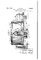
- Figure 1 is a vertical sectional View of the extractor showing one of the supporting logs, the vertical type motor being shown in elevation, the pulley of the latter being shown in section;
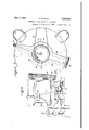
- Figure 2 is a fragmentary side elevational view showing the control lever connected to the brake and the dotted lines showing one of the controlling switches;
- FIG. 3 is a fragmentary sectional view showing the arrangement of the toggle joint
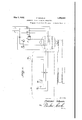
- Figure 4 is a wiring diagram showing the manner in which the control and motor for the hydro-extractor are wired.
- the metal leg may be a casting and comprise a base: or foot 2 which willbe bolted on a tional joint maybe oiled and kept free from dust.
- r v V 7 Still. referring to Figure 1, and to the supportzin question, there will be seen; two springs on this rod 8, the upper spring 12 being held in place by the nut 13, and the lower spring 14 being held in place and adjustably by the nut 15..v
- the guard is suspended so that the same is capable of a slight lateral motion or vibratory movement in a horizontal plane which motion willbe, transmitted to the hangers, and mostly absorbed rather than being transmitted to the floor on' which'the guardl'is, mounted.
- the guard through the connection of the feet, may be forced downwardly tightly in position, which, together with the weight-of, the machine, will prevent any rocking or tipping motion of the guard.
- the basket about to be described
- bracket 23 which bracket is secured to the side of the guard, the adjusting movement being regulated by thebolt 24, so that should it be necessary to tighten the belt 25, attached to'the pulley 26 onthe mainsupport or shaft 27, this may be done, and'the machine balanced by tightening the spring on theleg opposite the motor.
- the guard may move laterally or shift its position without in any way disturbing the torque of the shaft 27.
- FIG. 1 there Will be seen centrally of the bottom or guard plate 19, a central opening 28 in which there is mounted a casting 29, in turn held in position in the opening 28 by the bolts 30' which extend through holes 31of the casting, and holes 32 in the rim about the opening 38.
- the casting29. is a hollow one and is adapted to receive the main shaft 27, which shaft may be tapered at its lower end as at 36 to receive the hub of the beltpulley- 26, which pulley in turn islocked on by thenut37.
- pulley 26 is in theform of a double pulley, so that there may be placed about the rim 38 a brake 39 with the brake lining 40, which brake will be shortly described.
- the shaft 27 there may be seen-the collar or tube 41, in turn extending up to the ball race 42, while a small cover 43 may be seen at the top of the casting.
- Fixed near the upper end of the shaft 27' is the large metal ball or portion of one 44 while extending through this ball is the-small cross shaft 45 in turn held in position bythe key 46, the shaft or" stub extending slightly beyond the outer circumference of the said ball. 7
- the upper end of the shaft is, drilled as at 47 so that oil or grease may be fed to the ball bearing 42 and in turn drop down on the bearing 33.
- this basket 48 comprises a bottom plate 49, with the upstanding flanges 50 about its peripheral edge to which in turn is riveted the side wall 51 in turn provided with a plurality of holes or perforations 52.
- metal rings 53 are placed around the side wall, and I have found that four of them will provide the suflicient strength.
- the upper peripheral edge of the basket is provided with a heavy brass plate 54, riveted as at 55, while the inner peripheral edge of this plate is slightly rounded as at 59.
- the casting 60 Secured centrally of the bottom plate 49 of the basket is the casting 60 which is d0meshaped, having the lower outstanding flange 61 to which the bottom plate is securely riveted, there, of course, being an opening in the bottom plate to receive the casting.
- the internal diagneter of this casting is greater than the external diameter of the previously mentioned casting 29, so that the basket is free to tilt from the vertical to a slight degree.
- the upper inner surface of this casting 60 is in the form of a socket 63 to nicely or snugly fit the aforementioned ball 44.
- At the base of the socket there are two small cut out portions opposite the ends of the shaft 45, so that the said ends may fit within the cut out portion and bear against the adjacent walls of this cut out portion, so that a rotation of the shaft 27 and the cross shaft will in turn transmit rotation of the basket.
- the basket is what is known as freely mounted, or in other words, may tilt or rock slightly in any direc tion with relation to its shaft or support.
- the dome of the casting has a passageway therein, so that the upper end of the shaft 27 may extend therethrough and into the small housing or cover 63.
- the guard 20 in which is rotated the basket 48, it will be seen that it comprises the base 19 and the casting 29, and also comprises the outer wall 64, riveted at its lower edge by the rivets 65, the base plate having the flanges 66, while at the upper ends of the side wall 64 is the largerim 67, welded or otherwise fastened to the said side wall.
- outlet A there is an outlet for the water that is extracted from the material in the basket, and in Figure 3 I have shown the outlet A to which may be bolted a discharge pipe (not shown). Although I have not shown the specific construction of the outlet A, it will be understood that there is generally a small trough built in the bottom of the guard so that the water will flow into this trough and through the outlet A.
- the centrifugal force When the machine, that is, the basket, is rotated, the centrifugal force will cause the hook 71 to attain the position as shown, the jaws of the hook extending over the edge of the angle 70. However, when the centrifugal action ceases. the hook 71 will fall down wardly and become disengaged from the channel and permit the opening of the cover.
- the brake mechanism hereinafter described is not the primary feature of the present application but the description thereof is included in order that the funct on and operation of the subject-matter of the present invention may be better understood.
- the brake consists of two arms 39 pivoted at their one end as at 7 3. these arms being bowed in the center as at 7 3 to enc rcle or encompass the pulley 38 heretofore referred to. while a brake lining 40 is carried on each bowed portion of the arms as may be clearly seen in Figure 4.
- thearms 39 may then-be spread apart and pulled from beneath the machine, a new brake lining placed in pos tion and the brake again assembled.
- cable 80 that is, the insnlation or cover for the cable, extending through a switch 81 on the machine or con-,
- asmall switch 82 in its closed position when the lever 7 6 is thrown to its extreme limit to the left, so that the circuit throughthe lines A and B ( Figure 4) will be closed.
- lhis switch 82 will remain closed when the brake is off, that is, when the lever is all the way to the left, and will also remain closed, after the lever 76 has been shifted a slight degree to the right, and then the switch or contact is broken so that when the brakeis in a coasting position, the switch is open and the power is oh", and of course, the brake is oil.
- timing switch 81 If, however, the timing switch 81 is turned to its off position, that is, just opposite from the position shown in Figure 4, and the small switch'arm thrown to an upper position, it will beseen that the circuit is broken through A and B but a lead Y will be closed or thrown into circuit with the lead B, the current passing through Y up through the red light, R and over the power line P.
- a small knife-switch or other form of switch maybe placed in the main power line so that of course the current may be entirely cut off from the machine, in order'that the red light R will not operate when the machine is standing idle at night, or not in service.
- the basket has the ball center practically at the center of the basket, and does not have the weight concentrated. As the centers nearly coincide, an unbalanced weight may move the basket-axis away from the vertical, and the small restoring force will not overcome the friction of the supporting ball and socket to bring it back to vertical. However, the basket will operate just as well even though it revolves in a plane slightly from the horizontal.
- the shaft always remains parallel to its normal position and that the weight of practically the entire machine, plus the friction caused by the springs, tends to hold the machine from any rocking or jarring action, and at the same time allows a slight lateral action which is absorbed by the supports rather than being transmitted to the floor.
- the normal speed is about 750 R. P. M. and at this rate, the water will be quickly extracted from the material in the basket, and at the same time, the machine will run quietly and smoothly and with but relatively little lateral movement considering the mass that is rotated and the rate of rotation.
- a hydro extractor having a shaft for supporting a basket, a manually operated brake on said shaft provided with a handle, an electric motor for driving said shaft, a secondary electrical circuit including a solenoid operatively connected with said motor and said handle whereby when the brake is applied the current to the motor is out OK; when the brake is released the current to the elec tric motor is on; a cover for the hydro extractor and means connected to the cover and secondary circuit whereby the solenoid is deenergized and the motor is cut off when the cover is open.
- a hydro extractor having a basket therein, a shaft and a motor for rotating said shaft, a manually operated brake and means for operating the same, electric controls including a solenoid connected with the brake means, a cover for the hydro extractor, contacting means on the cover, and operating in the electric control means to de-energize the solenoid whereby the shaft cannot be started when the cover is in its open position.
Landscapes
- Engineering & Computer Science (AREA)
- Textile Engineering (AREA)
- Centrifugal Separators (AREA)
Description
May 3, 1932. F. SCHAUM 5 AUTOMATIC GUARD FOR HYDRO EXTRACTORS Original Filed March 29, 1928 3 Sheets-Sheet 1 gwwmtoz B kicker Saizazzm May 3, 1932. F. SCHAUM AUTOMATIC GUARD FOR HYDRO EXTRACTORS Original Filed March 29, 1928 5 Sheets-Sheet 2 May 3, 1932. SCHAUM 1,856,593
AUTOMATIC GUARD FOR HYDRO EXTRACTORS Original Filed March 29, 1928 3 Sheets-Sheet 3 abbomq Patented May 3, 1932 Miran STATES PATENT OFFICE FLETCHER SCI-IAUM, OF PHILADELPHIA, PENNSYLVANIA, ASSIGNOR T FLETCHER WORKS, 0F PHILADELPHIA, PENNSYLVANIA, A CORPORATION 035 PENNSYLVANIA AUTOMATIC GUARD FOR HYDBD-EXTRACTORS Original application filed March 29, 1928, Serial No. 265,761. Divided and this application filed November 10, 1928.
Thisinvention relates to new and useful improvements in an automatic guard adapted to be used upon extractors and it consists in the novel features hereinafter described 5, and claimed.
The subject-matter of the present invention is divided out of my earlier application for patent for hydro-extractor, filed March 29, 1928, Serial No. 265,761.
The guard is especially adapted to be used upon extractors or centrifugal machines of the large capacity type and adapted to handle heavy bags, nets, bulk work, yarn, etc., and wherein the balancing arrangement, that is, the three point suspension of the guard, the supporting shaft fixedly mounted in the guard, and a freely mounted basket on the shaft, increases the balancing action and en ables the machine to handle unbalanced loads without calling for any adjustment.
An object of the invention is to provide a device of the character stated adapted to be used upon extractors that may be quickly and easily started and also quickly and readily stopped and wherein the starting, coasting and stopping operations are controlled from a single source, the brake lever, which has three positions.
A. further object of the invention is to arrange the extractor and its control so that when in the first or running position the brake is off and the power is on,in,the second or coasting position, both the brake and the power are ofi, while in the third or stopping position, the brake is on and the power is 011'.
It is to be remembered that some of these extractors weigh 3800 pounds and the baskets are 48 inches in diameterand when trav cling at 750 R. P. M., exert a tremendous centrifugal force.
Another object of the invention is to provide an extractor wherein the cover is interlocked and cannot be raiseduntil the basket comes to a full stop, nor can the machine be started until the cover is closed.
A still further object of the invention is to provide'an extractor with very fast acceleration. a high running speed and a relative- 50 ly quick stop.
Serial N0. 318,409.
Still another object of the invention is to provide a hydro-extractor wherein the entire machine is stopped at three different points and the machine so hung that the central shaft or support may be connected by a belt to a motor, which motor is mounted on the guard so that there will be no differences in the torque regardless of the lateral movement of the guard and basket.
' Still another object of the invention is to provide a hydro-extractor suspended from three points so that the weight of the machine will tend to overcome any gyrations which might otherwise be present in the extractor, that is, gyrations of the central shaft and guard.
The basket is preferably freely mounted on the shaft so that the same may occupy, if necessary, a plane other than the horizontal.
A still further object of the invention is to provide a hydro-extractor wherein the basket is mounted freely but the shaft and the guard are so arranged that there may be a slight lateral movement of the guard and shaft so that the vibration in turn may be taken up in the three points of support, rather than being transmitted directly to the floor on which the machine is mounted.
With these and other objects in view the invention consists in certain new and novel arrangements, and combination of parts as will be hereinafter more fully described and pointed out in the claims.
Referring now to the drawings showing a preferred embodiment of the invention.
Figure 1 is a vertical sectional View of the extractor showing one of the supporting logs, the vertical type motor being shown in elevation, the pulley of the latter being shown in section;
Figure 2 is a fragmentary side elevational view showing the control lever connected to the brake and the dotted lines showing one of the controlling switches;
Figure 3 is a fragmentary sectional view showing the arrangement of the toggle joint, and
Figure 4 is a wiring diagram showing the manner in which the control and motor for the hydro-extractor are wired.
This application is directed particularly to the automatic guard for an extractor or centrifugal machine and throughout the following specification reference is being made to coacting features and arrangements in order 'that the present invention may be clearly and fully understood.
Referring now more specifically to Figs. 1 and2 there will be seen three metal supporting legs 1, and as they are alike, a descrip tion of one will be a description of all. The metal leg may be a casting and comprise a base: or foot 2 which willbe bolted on a tional joint maybe oiled and kept free from dust. r v V 7 Still. referring to Figure 1, and to the supportzin question, there will be seen; two springs on this rod 8, the upper spring 12 being held in place by the nut 13, and the lower spring 14 being held in place and adjustably by the nut 15..v
' On the lower end of the hanger on the rod 8 there .willbe seen in position, another ball .16 or a portion of one, designed to fit tightly within a socket 17 in aleglS of the base plate 19 of the guard 20.- There is also the opening 21 extending to the socket 17 so that the. aforementionedrod 8 may pass down into the same.
- As mentioned heretofore, thereare three of the lugs or supports which engage and cooperate with the'three feet or lugs 18 :disposed in certain spaced relation about the base plate of the guard. a r As far as the specification has proceeded, it will be seen that the guard is suspended so that the same is capable of a slight lateral motion or vibratory movement in a horizontal plane which motion willbe, transmitted to the hangers, and mostly absorbed rather than being transmitted to the floor on' which'the guardl'is, mounted.
'By' having the adjustable springs on the hangers, the guard, through the connection of the feet, may be forced downwardly tightly in position, which, together with the weight-of, the machine, will prevent any rocking or tipping motion of the guard. In other words, when the basket about to be described,
rot-ates in ahigh rate of speed in the guard. there would be'a tendency to have the guard rock or tilt unless spring pressure is exerted to tightly hold the guard on the hangers. However, due to the frictional contact of the balls and the respective sockets, plus the weight ofthe machine and the spring pressure, the guard will move laterally or may possibly be shifted slightly about its three points of suspension, but will not rock or tilt to any appreciable degree, and as'far as can be seen, will always be sustained in a horizontal plane.
Furthermore, there is a motor 22 adj ustable longitudinally on the bracket 23, which bracket is secured to the side of the guard, the adjusting movement being regulated by thebolt 24, so that should it be necessary to tighten the belt 25, attached to'the pulley 26 onthe mainsupport or shaft 27, this may be done, and'the machine balanced by tightening the spring on theleg opposite the motor.
By mounting the motor on the guard, the guard may move laterally or shift its position without in any way disturbing the torque of the shaft 27.
The explanation of the manner of support and the shaft 27 is set out rather fully, but it is of great importance, as unless the machine is properly supported and proper spring provided, and unless the drive shaft in turn is properly supported Within the guard,the machine would vibrate or rock due ltio the centrifugal force of the rotating bas- Understanding now, therefore, how the machine is mounted or susended, a more specific description will follow of the shaft, guard andbasket, control and brake.
Referringto Figure 1 in particular, there Will be seen centrally of the bottom or guard plate 19, a central opening 28 in which there is mounted a casting 29, in turn held in position in the opening 28 by the bolts 30' which extend through holes 31of the casting, and holes 32 in the rim about the opening 38.
Near the bottom of the casting is the ball race 33' in turn fitting on the thrust bearing 34 while a wick 35 maybe seen at the lower end of the casting. The casting29. is a hollow one and is adapted to receive the main shaft 27, which shaft may be tapered at its lower end as at 36 to receive the hub of the beltpulley- 26, which pulley in turn islocked on by thenut37. I
It might be mentionedat this point that the pulley 26 is in theform of a double pulley, so that there may be placed about the rim 38 a brake 39 with the brake lining 40, which brake will be shortly described.
About the shaft 27, there may be seen-the collar or tube 41, in turn extending up to the ball race 42, while a small cover 43 may be seen at the top of the casting. Fixed near the upper end of the shaft 27' is the large metal ball or portion of one 44 while extending through this ball is the-small cross shaft 45 in turn held in position bythe key 46, the shaft or" stub extending slightly beyond the outer circumference of the said ball. 7 The upper end of the shaft is, drilled as at 47 so that oil or grease may be fed to the ball bearing 42 and in turn drop down on the bearing 33. When the motor, therefore, is started, the shaft 27 and its ball and stub shaft may be rotated to in turn rotate the basket 48, now to be described.
B aslcet While the basket mechanism hereinafter described is not a primary feature of the present application, the description thereof is included in order that the subject-matter of the present application may be better understood.
As may be seen in Figure 1, this basket 48 comprises a bottom plate 49, with the upstanding flanges 50 about its peripheral edge to which in turn is riveted the side wall 51 in turn provided with a plurality of holes or perforations 52. To strengthen this basket, metal rings 53 are placed around the side wall, and I have found that four of them will provide the suflicient strength. The upper peripheral edge of the basket is provided with a heavy brass plate 54, riveted as at 55, while the inner peripheral edge of this plate is slightly rounded as at 59.
Secured centrally of the bottom plate 49 of the basket is the casting 60 which is d0meshaped, having the lower outstanding flange 61 to which the bottom plate is securely riveted, there, of course, being an opening in the bottom plate to receive the casting.
The internal diagneter of this casting is greater than the external diameter of the previously mentioned casting 29, so that the basket is free to tilt from the vertical to a slight degree. The upper inner surface of this casting 60 is in the form of a socket 63 to nicely or snugly fit the aforementioned ball 44. At the base of the socket there are two small cut out portions opposite the ends of the shaft 45, so that the said ends may fit within the cut out portion and bear against the adjacent walls of this cut out portion, so that a rotation of the shaft 27 and the cross shaft will in turn transmit rotation of the basket. I I
From this it will be seen that the basket is what is known as freely mounted, or in other words, may tilt or rock slightly in any direc tion with relation to its shaft or support.
I The dome of the casting has a passageway therein, so that the upper end of the shaft 27 may extend therethrough and into the small housing or cover 63.
Referring now for the moment to the guard 20, in which is rotated the basket 48, it will be seen that it comprises the base 19 and the casting 29, and also comprises the outer wall 64, riveted at its lower edge by the rivets 65, the base plate having the flanges 66, while at the upper ends of the side wall 64 is the largerim 67, welded or otherwise fastened to the said side wall. I
Of course there is an outlet for the water that is extracted from the material in the basket, and in Figure 3 I have shown the outlet A to which may be bolted a discharge pipe (not shown). Although I have not shown the specific construction of the outlet A, it will be understood that there is generally a small trough built in the bottom of the guard so that the water will flow into this trough and through the outlet A.
Referring for the moment to Figure 2, there will be seen a cover 68 hinged as at 69, and a handle 70, so that when the clothes are to be inserted or removed from the basket, this cover may be thrown back.
I have provided a little safety device for always holding the cover in position when the basket is rotating, by placing a small channel iron 70 centrally of the cover, and to cooperate with this small hook 71 (see Figure 1) is pivoted the small housing 63.
When the machine, that is, the basket, is rotated, the centrifugal force will cause the hook 71 to attain the position as shown, the jaws of the hook extending over the edge of the angle 70. However, when the centrifugal action ceases. the hook 71 will fall down wardly and become disengaged from the channel and permit the opening of the cover.
I provide this as it is dangerous to try and remove anything from the basket even though the same is rotating at a low rate of speed, it having caused operators at different times to have their arms torn from the shoulder.
The brake mechanism hereinafter described is not the primary feature of the present application but the description thereof is included in order that the funct on and operation of the subject-matter of the present invention may be better understood.
Brake mechanism Referring now to the braking mechanism 39, and referring to Figures 1, 3 and 4 in particular. it will be seen that the brake consists of two arms 39 pivoted at their one end as at 7 3. these arms being bowed in the center as at 7 3 to enc rcle or encompass the pulley 38 heretofore referred to. while a brake lining 40 is carried on each bowed portion of the arms as may be clearly seen in Figure 4. The outer ends of these arms 39 are connected by bolts and links 75 to an operating lever 76, pivoted as at 77 so that when the handle 76 is thrown to the right (Figure 3), it will lilQlllZlV pull these arms toward each other to thus tightly grip the brake band 40 about the pulley 38 and thus slow down or stop the machine.
Then the lever 7 6 is in the position shown in Figure 3, the outer ends of the brake arms are slightly forced apart, thus removing the tension about the pulley connected to the lower end of the shaft 27.
Ill)
By using this toggle arrangement, great force can be applied to the brake, which of course is necessary, asit is to be remembered in the large size the rota-ting basket weighs approximately 1700 pounds, and revolves at about 750R. Pshil. i There is another advantage of having the brake formed in the manner just described, and that-is, it will be noticed that it is not necessary to remove the basket or the central shaft when desired to reline the brake, which has to be done more or less frequently.
In the present instance, all that is necessary, is to release the pin 72 and remove the links and bolts at the outer ends of the arms 39. I
In this manner, thearms 39 may then-be spread apart and pulled from beneath the machine, a new brake lining placed in pos tion and the brake again assembled.
Uontrols As previously mentions-din the application, the starting, coasting and stopping operations are controlled from a single source, that is, after the current is onceiturned on.
i As also heretofore mentioned, in the first or running position, the brake, is off and the power is on, but the cover must be closed before the machine will start, as Wlll be shortlydescribed. In the second, or coasting position, both brake and power are off; while in the third orstopping position, the brake is on and the power is off. This is accom-. plished by an electrical wiring system and switches and relays, which are diagrammatically shown in Figure 4, in cooperation with the handle 76, heretofore mentioned.
Referring to Figure 2 for the moment,
there will-be seen a. cable 80, that is, the insnlation or cover for the cable, extending through a switch 81 on the machine or con-,
nected or positioned on a wall or other convenient place. q
Still referring to Figure 2, there may be seen in dottedlines, asmall switch 82 in its closed position when the lever 7 6 is thrown to its extreme limit to the left, so that the circuit throughthe lines A and B (Figure 4) will be closed. lhis switch 82 will remain closed when the brake is off, that is, when the lever is all the way to the left, and will also remain closed, after the lever 76 has been shifted a slight degree to the right, and then the switch or contact is broken so that when the brakeis in a coasting position, the switch is open and the power is oh", and of course, the brake is oil.
Referring for the moment to Figure 1,
there will be seen a small switch box containing the top cover switch 83, so that when the cover is open, the circuit through A and B will'be broken, and the machine cannot be started even thoughthe timing switch be thrown on or the switch 82 be in operative (p si ion, hus m k g it impossible to start the r ation of the baske hen the cover is in its ope pos tion- It will be seen that the line A runs to a magnetic contact or solenoid C from which a lead extends over to one power line P. There is also a connection at the point X from which there is a lead to a green light G to show an operator, whether the machine is running or idle. 7
From the green light Gr extends a lead H so that when the shaft C of'the solenoid is pulled inwardly, the switch arm H will contact with the other power line 1 At the same time the power line P will be closed through the small arm H", so that the motor may be energized and the center shaft 27 and the basketbe set in motion.
If, however, the timing switch 81 is turned to its off position, that is, just opposite from the position shown in Figure 4, and the small switch'arm thrown to an upper position, it will beseen that the circuit is broken through A and B but a lead Y will be closed or thrown into circuit with the lead B, the current passing through Y up through the red light, R and over the power line P.
A small knife-switch or other form of switch maybe placed in the main power line so that of course the current may be entirely cut off from the machine, in order'that the red light R will not operate when the machine is standing idle at night, or not in service.
It'will be seen that there is a timing circuit for the motor and that there is really an operating circuit for energizing the motor by the different control set forth.
From this description of the controls and wiring diagram, it will be seen that the machine is always .under the control of the operator, and that when the machine is running and the brake off, the power is on, but when the brake is on or when the machine is coasting, the power is off. Furthermore, it is impossible to run the machine when the cover is open, and lastly signal lights always show whether the machine. has been stopped or whether it is in operation.
Resume From the foregoing, the operation of the machine will be readily understood, as the machine is very simple to operate. The control handle 7 6, when manipulated, will either start or stop the machine or allow the same to coast. V v a As in all rotating bodies, there is what is known as the critical point, and after the machine is first started the basket may rock or tilt slightly, that is when traveling around 300 or 400 revolutions per minute, but when this point is passed, the rotation of the basket is verysmooth. e
By providing springs and adjusting them,
so that the front spring exerts about 800 pounds pressure, and the two back springs 650 pounds pressure; or in other words, adjusting the supporting spring to offset the difference in weight on the three lugs, due to the overhang of the motor at the back, it is possible to handle a very great unbalanced load in the basket.
Furthermore, by using three balancing or supporting posts which are vertical and therefore parallel with each other and parallel with the extractor shaft, any oscillation would raise the whole machine parallel to its normal position.
The machine described should not be run above a normal speed of say 750 R. P. M., as at a higher rate, it will jump, or tend to pound.
It will be noticed that the basket has the ball center practically at the center of the basket, and does not have the weight concentrated. As the centers nearly coincide, an unbalanced weight may move the basket-axis away from the vertical, and the small restoring force will not overcome the friction of the supporting ball and socket to bring it back to vertical. However, the basket will operate just as well even though it revolves in a plane slightly from the horizontal.
It will also be noticed that the shaft always remains parallel to its normal position and that the weight of practically the entire machine, plus the friction caused by the springs, tends to hold the machine from any rocking or jarring action, and at the same time allows a slight lateral action which is absorbed by the supports rather than being transmitted to the floor. As before stated, the normal speed is about 750 R. P. M. and at this rate, the water will be quickly extracted from the material in the basket, and at the same time, the machine will run quietly and smoothly and with but relatively little lateral movement considering the mass that is rotated and the rate of rotation.
I am aware that it is old to provide extractors to carry unbalanced loads designed to travel at a very high rate of speed, and wherein the basket and its shaft are designed for free gyration, but it will be seen and understood that with my device, the entire weight of the machine is so suspended as to prevent free gyration. Also, heavy springs between the frictional contacts are used to overcome and restrict, as far as possible any gyratory movement of the guard and its rotating shaft.
Many slight changes may be made without in any way departing from the spirit and scope of the invention.
Having thus described'my invention, what I claim as new and desire to secure by Letters Patent is 1. A hydro extractor having a shaft for supporting a basket, a manually operated brake on said shaft provided with a handle, an electric motor for driving said shaft, a secondary electrical circuit including a solenoid operatively connected with said motor and said handle whereby when the brake is applied the current to the motor is out OK; when the brake is released the current to the elec tric motor is on; a cover for the hydro extractor and means connected to the cover and secondary circuit whereby the solenoid is deenergized and the motor is cut off when the cover is open.
2. A hydro extractor having a basket therein, a shaft and a motor for rotating said shaft, a manually operated brake and means for operating the same, electric controls including a solenoid connected with the brake means, a cover for the hydro extractor, contacting means on the cover, and operating in the electric control means to de-energize the solenoid whereby the shaft cannot be started when the cover is in its open position.
3. A hydro extractor, three points of suspension, means therefor to thereby equally distribute the weight on said means, a shaft in said extractor and a basket on said shaft, a guard about said basket, a cover on said guard, a finger carried by said shaft centrifugally operated for interlocking with said cover when said basket is rotated, and said finger released when said shaft is idle, a motor for driving said shaft, an energizing circuit including a solenoid. and control means therefor connected with said motor, a brake on said shaft, and said brake operating said control means whereby when the brake is on the power is off, and when the brake is off the power is on.
In testimony whereof I affix my signature.
FLETCHER SOHAUM.
Priority Applications (1)
| Application Number | Priority Date | Filing Date | Title |
|---|---|---|---|
| US318409A US1856593A (en) | 1928-03-29 | 1928-11-10 | Automatic guard for hydro-extractors |
Applications Claiming Priority (2)
| Application Number | Priority Date | Filing Date | Title |
|---|---|---|---|
| US265761A US1766310A (en) | 1928-03-29 | 1928-03-29 | Hydro extractor |
| US318409A US1856593A (en) | 1928-03-29 | 1928-11-10 | Automatic guard for hydro-extractors |
Publications (1)
| Publication Number | Publication Date |
|---|---|
| US1856593A true US1856593A (en) | 1932-05-03 |
Family
ID=26951415
Family Applications (1)
| Application Number | Title | Priority Date | Filing Date |
|---|---|---|---|
| US318409A Expired - Lifetime US1856593A (en) | 1928-03-29 | 1928-11-10 | Automatic guard for hydro-extractors |
Country Status (1)
| Country | Link |
|---|---|
| US (1) | US1856593A (en) |
-
1928
- 1928-11-10 US US318409A patent/US1856593A/en not_active Expired - Lifetime
Similar Documents
| Publication | Publication Date | Title |
|---|---|---|
| US1766310A (en) | Hydro extractor | |
| US2658372A (en) | Washing machine | |
| US3226016A (en) | Industrial centrifuges | |
| US2793757A (en) | Centrifugal-type washing machine | |
| US1856593A (en) | Automatic guard for hydro-extractors | |
| US1641780A (en) | Extractor | |
| US1905950A (en) | Drive release and brake for extractors | |
| US2574617A (en) | Washing machine | |
| US3306582A (en) | Fire escape device | |
| US1753722A (en) | Support for centrifugals | |
| US3363772A (en) | Extractor | |
| US3226960A (en) | Washing machine unbalance control | |
| US1882968A (en) | Clear top extractor | |
| US3159257A (en) | Speed responsive clutch with variable means | |
| US1188098A (en) | Brake for centrifugal extractors. | |
| US1502677A (en) | Centrifugal drier | |
| US2481867A (en) | Motor and clutch unit | |
| US2524678A (en) | Suspended gyratory centrifugal | |
| US2693866A (en) | Electromagnetically controlled brake | |
| CN2262951Y (en) | Tripodia bag-turning type automatic slag tap centrifuger | |
| US397243A (en) | Island | |
| US1501163A (en) | Extractor drive mechanism | |
| US656908A (en) | Centrifugal machine. | |
| US2383671A (en) | Starting mechanism and the like | |
| US1764214A (en) | Centrifugal extractor |