US1856589A - Concrete flume structure and method of building same - Google Patents
Concrete flume structure and method of building same Download PDFInfo
- Publication number
- US1856589A US1856589A US538072A US53807231A US1856589A US 1856589 A US1856589 A US 1856589A US 538072 A US538072 A US 538072A US 53807231 A US53807231 A US 53807231A US 1856589 A US1856589 A US 1856589A
- Authority
- US
- United States
- Prior art keywords
- concrete
- ties
- flume
- forms
- side walls
- Prior art date
- Legal status (The legal status is an assumption and is not a legal conclusion. Google has not performed a legal analysis and makes no representation as to the accuracy of the status listed.)
- Expired - Lifetime
Links
- 239000004567 concrete Substances 0.000 title description 95
- 238000000034 method Methods 0.000 title description 22
- 230000003014 reinforcing effect Effects 0.000 description 19
- 238000010276 construction Methods 0.000 description 10
- 239000000463 material Substances 0.000 description 9
- 229910001294 Reinforcing steel Inorganic materials 0.000 description 7
- 229910000831 Steel Inorganic materials 0.000 description 6
- 239000010959 steel Substances 0.000 description 6
- 238000009412 basement excavation Methods 0.000 description 3
- 238000005266 casting Methods 0.000 description 3
- XLYOFNOQVPJJNP-UHFFFAOYSA-N water Substances O XLYOFNOQVPJJNP-UHFFFAOYSA-N 0.000 description 3
- RYGMFSIKBFXOCR-UHFFFAOYSA-N Copper Chemical compound [Cu] RYGMFSIKBFXOCR-UHFFFAOYSA-N 0.000 description 2
- 229910052802 copper Inorganic materials 0.000 description 2
- 239000010949 copper Substances 0.000 description 2
- 230000001105 regulatory effect Effects 0.000 description 2
- 230000002787 reinforcement Effects 0.000 description 2
- 230000002441 reversible effect Effects 0.000 description 2
- 239000004576 sand Substances 0.000 description 2
- 125000006850 spacer group Chemical group 0.000 description 2
- 241000935974 Paralichthys dentatus Species 0.000 description 1
- 239000004568 cement Substances 0.000 description 1
- 238000005336 cracking Methods 0.000 description 1
- 238000007599 discharging Methods 0.000 description 1
- 239000000945 filler Substances 0.000 description 1
- -1 gravel Substances 0.000 description 1
- 239000011440 grout Substances 0.000 description 1
- 230000003137 locomotive effect Effects 0.000 description 1
- 239000000203 mixture Substances 0.000 description 1
- NJPPVKZQTLUDBO-UHFFFAOYSA-N novaluron Chemical compound C1=C(Cl)C(OC(F)(F)C(OC(F)(F)F)F)=CC=C1NC(=O)NC(=O)C1=C(F)C=CC=C1F NJPPVKZQTLUDBO-UHFFFAOYSA-N 0.000 description 1
- 239000004540 pour-on Substances 0.000 description 1
- 239000011150 reinforced concrete Substances 0.000 description 1
- 239000011435 rock Substances 0.000 description 1
- 238000005096 rolling process Methods 0.000 description 1
- 239000007787 solid Substances 0.000 description 1
- 238000012384 transportation and delivery Methods 0.000 description 1
- 239000002023 wood Substances 0.000 description 1
Images

Classifications
-
- E—FIXED CONSTRUCTIONS
- E02—HYDRAULIC ENGINEERING; FOUNDATIONS; SOIL SHIFTING
- E02B—HYDRAULIC ENGINEERING
- E02B9/00—Water-power plants; Layout, construction or equipment, methods of, or apparatus for, making same
- E02B9/02—Water-ways
- E02B9/04—Free-flow canals or flumes; Intakes
-
- Y—GENERAL TAGGING OF NEW TECHNOLOGICAL DEVELOPMENTS; GENERAL TAGGING OF CROSS-SECTIONAL TECHNOLOGIES SPANNING OVER SEVERAL SECTIONS OF THE IPC; TECHNICAL SUBJECTS COVERED BY FORMER USPC CROSS-REFERENCE ART COLLECTIONS [XRACs] AND DIGESTS
- Y02—TECHNOLOGIES OR APPLICATIONS FOR MITIGATION OR ADAPTATION AGAINST CLIMATE CHANGE
- Y02E—REDUCTION OF GREENHOUSE GAS [GHG] EMISSIONS, RELATED TO ENERGY GENERATION, TRANSMISSION OR DISTRIBUTION
- Y02E10/00—Energy generation through renewable energy sources
- Y02E10/20—Hydro energy
Definitions
- pro-casting concrete ties to support and secure reinforcing steel employed in the flume and-to form a road-bed to support rails and planks over which trucks, tractors, concrete mixers, and other similar equipment may travel to deliver forms, sand, gravel, cement,
- third to provide a method of supporting and securing side wall forms with relation to the ties whereby the forms may be readily erected and removed as required; and fourth, to provide a method of delivering and pouring the concrete to form the bottom and side walls of the flume in one integral unit.
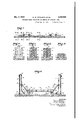
- Fig. 1 is a cross section of an excavated bench showing a concrete tie in position thereon.
- Fig. 2 is an enlarged end view of a concrete tie taken on line II-II of Fig. 1.
- Fig. 3 is an enlarged cross section of the tie taken on line III-III of Fig. 1.
- Fig. 4 is an enlarged cross section of the tie taken on line IV-IV of Fig. 1.
- Fig. 5 is an enlarged cross section of the tie taken on line VV of Fig. 1.
- Fig. 6 is a cross section showing the side wall forms erected and placed in position on the ties, said view also showing a part of the road bed over which the equipment may travel during construction of the flume.
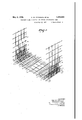
- Fig. 7 is a perspective view showing the manner of placing the reinforcing steel in the construction of the flume.
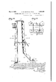
- Fig. 8 is an enlarged cross section of one of the side wall forms.
- Fig. 9 is a partial plan view of the same.
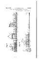
- Fig. 10 is a side elevation of the form 1931. Serial No. 538,072.
- FIG. 8 looking in the direction of arrow a.
- Fig. 11 is an enlarged side elevation of the form shown in Fig. 8 looking in the direction of arrow 6.
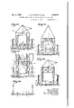
- Fig. 12 is a cross section of the flume showing the form setting jumbo.
- Fg. 13 is a crosssection of the flume showing the tractor turning jumbo.
- Fig. 14 is a cross section of the flume showing the concrete mixing jumbo.
- Fig. 15 is a cross section of the flume showing the form removing jumbo.
- Fig. 16 is a cross section of the flume showing the side wall forms removed and the road bed prior to removal.
- Fig. 17 is a longitudinal, central section of the flume showing the several jumbos in operating position.
- Fig. 18 is a similar section showing a part of the completed flume and showing the form removing jumbo in operating position.
- the flume shown in the present applicat on is particularly designed to carry water from the intake head of a certain river to a power house located some twenty miles away.
- the flume is constructed of reinforced concrete and is built for a greater part on a bench excavated from the solid of the hillside, and where the flume crosses ravines and rivers. bridges, siphons, etc., are employed.
- the country through which the flume passes is rather rough and inaccessible, hence transportation and delivery of material required for the construction of the flume became one of the major problems.
- a method of construction has been employed which permits the flume bed and structure to be employed as a roadway for hauling and delivering material both during and after construction of the flume.
- the excavation of the bench is accomplished in any suitable manner. For instance, first by clear ng away trees and other obstructions and then excavating by means of power shovels. The excavation is kept close to grade so that there will be a minimum of material to be compacted when bringing thebench to proper grade. After excavation the bench is trimmed and rolled with may be employed. They are placed at suitable intervals along the bench. Reinforcing rods are laid in the forms and the concrete is poured. The reinforcing rods extend from end to end of .eachtie and are ind cated at 22 in Figs. 1 to 5, respectively. Rods project through the ends of the ties as indicated at 3 and the function of the projecting ends will hereinafter be described.
- the ties are cast with a pair of rectangular pedestal like projections adjacent each end as indicated at 4 and 5.
- the tops "of said'pedestals are set at the elevation of the inner surface of the bottom portion of the flume and a groove is cast around the projections as indicated at 6 for the purposeof binding theties to the flame bottom since the ties are incorporated in the bottom pour.
- the outermost pedestals indicated at 4 are provided with staples 7 which are tied to the re nforcing rods 2 as shown in Fig. 3.
- the inside'steelforms hereinafter to be described are secured by means of the staples "and wedges driven therethrough.
- the innermost pedestals indicated at 5 are provided with dowel holes 8 which are formed just after the concrete has been poured and before it takes its initial set and these dowel holes receive p ns whereby spacer blocks and woodenties are temporarily secured to support a board track 9, and rails 9a.
- the inner pedestals 5 are also employed to secure bracing rods 26 which are connected with the inner forms. Outside forms are also supported by the ties. The outside forms are placed on the outer ends of the ties and are 7 there secured by -means. of hook-shaped clamps which are attached to the projecting ends 3 of the reinforcing rods 2.
- construction joints spaced approximately 20 feet apart are employed. They consist of copper seals which direct the cracking to a particular location, which is sealed to prevent leakage.
- the copper seals are pressed into shape in hydraulic dies and are furnished in three pieces to the joint,'one piece for the flame bottom. and one piece for each of the side walls, the joints are brazed after the seal is in place.
- the fiume is thus made of a series of concrete pieces approximately 20 feet long since the concrete and reinforcing is cut through'at these intervals.
- the reinforcing steel when placed in position is tiedtogether in any suitable'manner and the forms forming the side walls are ready to be placed in position.
- Each side wall requires two formsand steel forms are used. These consist of steel panels of uniform height and length with a few shorter panels in order to assist in setting the forms where curves are encountered. Enough forms .to permit one group to remain in place during initial setting of the concrete while one group is in place and being poured and a third, group are being placed in position are provided.
- the method of securing the steel forms is best shown in Figs. 8 and 9.
- the inner forms are indicated at 16 and the outer forms at 17.
- the inner forms have an angular foot extension 18 which-forms a filler between the bottom and the side walls of the flume.
- the inner forms are supported on the pedestals 4 being there secured by wedges 19 which engage a foot flange 20 and which are driven through the staples 7 previously described.
- the outer forms 17 are placed on the outer ends of the ties and there secured by hookshaped clamps 21 which are slipped over the end projections 3 of the tie reinforcing rods and secured in position by wedges 22.
- the upper ends of the forms are provided with perforated flanges 23 and horizontal spacing 'bars' 24: are placed at suitable intervals.
- the forms may also be tied together intermediate their upper and lower ends by turnbuckles such as indicated at 25.
- the inner forms are braced by means of rods 26.
- the rods 26 telescope into tubes 27 and as such are adjustablethey are perforated as indicated at 28 and a pin may be passed through them when the desired adjustment is obtained.
- the lower ends of the tubes are secured to anchor plates 29 which in turn are secured on the inner pedestals 5 by means of the dowel pins 8.
- the dowel pins 8 are placed in the holes formed in the inner pedestals indicated at 5.
- the anchor plates 29 are then slipped over the dowel pins, spacing blocks 30 are next applied, see Fig. 6, and wooden ties 31 having holes drilled in their outer ends are also applied.
- the boa rdwalk or runway 9 is then placed in position on the ties 31 and the rails 9a are secured in any manner desired.
- An overhead runway is thus formed to support equipment whereby the forms may be moved from place to place, that is, set up, taken down etc., said runway also functioning as a support for tractors, trailers, and so on whereby material in general is handled.
- suitable equipment is employed to transport the forms to position after which they are erected and secured as previously described and when the forms are in place the pouring of the concrete may take place.
- the equipment employed comprises industrial tractors provided with pneumatic tires to haul trailers.
- the trailers are designed to track in both directions because the board track over the fresh concrete or the ties does not permit of much width on curves and for this reason both of the trailer axles are equipped with fifth wheels.
- Suitable bodies are placed on the trailers which may be over balanced and readily dumped.
- Other equipment employed are the steel forms alreac y described.
- the material forming the concrete is handled by concrete jumbos. Any suitable number may be employed.
- the concrete jumbos are fabricated steel structures approximately 14 feet high from the rails, about 13 feet long and 10 feet wide. They are self propelling being driven by five horsepower motors through reduction 7 gears and a system of shafts, sprockets and chains.
- the concrete jumbos are equipped with a loading hopper which elevates the sand, rock, etc, from the trackway to the mixer. Any suitable mixer may be employed and the mate-rial raised by the loading hopper is delivered to the mixer.
- the concrete is discharged through a double sliding gate which slides both ways from a central or closed position into a hopper directly beneath the mixer and from the hopper the concrete flows through chutes to two belt conveyors extending from opposite sides of the mixer hopper through the frame to points directly above the fiume sides.
- the belt couveyors are operated by three horse-power motors and are reversible.
- the speed of discharging concrete from the mixer is regulated by the opening of mixer gates and the amount of concrete delivered to each of the belt conveyors is regulated by a deflector of the nature of a butterfly valve built into the side of the mixer hopper.
- the concrete j umbo described is best illustrated in Figs. 14 and 17.
- a tractor or hoisting jumbo is shown in Figs. 13 and 17, form setting and stripping jumbos are shown in Figs. 15, 17 and 18.
- the value of the equipment and the general mode of procedure is that it permits of pouring the flume without joints between the bottom and the side walls so as to produce a flume which is a monolithic structure.
- the procedure of hauling and pouring is as follows: A train composed of a tractor 45, see Figs. 17 and 18, and train of trailers 46 proceeds to the rear of the concrete jumbo indicated at 32. The tractor is cut loose and runs through the mixer jumbo and underneath the tractor hoisting jumbo indicated at 33 where the tractor driver picks the tractor up and leaves it suspended in the air.
- Every successive trailer 46 is cut loose at the concrete jumbo and the load dumped into the hopper 34.- and when the hopper is in the air the empty trailers are shoved ahead through the mixer jumbo and the tractor hoisting jumbo.
- the tractor is lowered in front of the train pointing in the reverse direction, it having been turned around while it was hanging on the crane hook. The tractor then moves out with its train of empties and goes back to the loading bins for loading. The procedure is the same for each train serving the concrete jumbo.
- the first concrete placed is poured into the side forms and under the action of tampers fills the beveled space under the bottom of the inside forms and flows inwardly for about a foot or so between the concrete ties.
- the concrete stands about half way up in the side forms at this time.
- the concrete jumbo is moved back and forth along the particular section being poured when the concrete is being placed.
- the belt conveyors 35, see Fig. 14, delivering the concrete to the side forms are then reversed and the concrete is discharged into a hopper 36 which feeds a short section of pipe 37 which is swivel connected to the underside of the hopper.
- wood troughs or the like may be employed to deliver the water to the burlap.
- the forms are set up in advance of the concrete jumbo so that this may be maintained in continuous'operation.
- the forms are removed by the stripping jumbo whenthe concrete has set sufficiently; They are loaded on cars such as indicated as 37, see Figs. 17 and 18, and hauled by a tractor such as shown at L5 to the form setting jumbo indicated at 38.
- a tractor such as shown at L5 to the form setting jumbo indicated at 38.
- one group of forms are being stripped and set up, another group of forms are already set in position ready to receive the concrete, and a third group is in place while the concrete is setting. WVhen the concrete'has set for two or three days the rails, boardwalk, cross ties, spacer blocks, anchor plates, and dowel pins may be removed.
- the holes in which the dowel pins wereplaced are filled up with concrete grout or likemate'rial and smoothed over and when this is set the bottom of the flume serves as a trackway for the tractors 45 and the trailers indicated at 4:6 and 37.
- a portion of-the finished flume isshown in Fig. 18 and aportion under construction is shown at 39, an incline 450 being formed between the finished bottom of the flume and the trackway to permit the tractors and trailers to reach the elevated track or the flumebottom as the case may be.
- An average of 150 feet of flume per one shift day has been poured and completed with the equipment shown and from present indications it is expected that an average of 180 feet or more per shift will be made.
- the finishing of the subgrade, the'pouring of the ties and placing of reinforcing steel keeps pace with the pouring of the concrete and the work is thus continuously advancing at a rapid rate.
- Ties are cast in advance of the fiume structure and function as a support for the reinforcing steel and transportation system, the forms, the equipment for mixing and placing the concrete and other miscellaneous equipment, the ties finally becoming a part of the completed structure.
- A. novel equipment is employed for mixing and placing of concrete, for talking down and setting up the forms, and the equipment is so constructed as not to interfere with transportation through the completed flume or that section of the flume'which is under construction.
- the completed structure is employed as a roadway for pneumatic equipment or otherwise over which the materials required may be hauled.
- a method of constructing concrete flumes which consists in pre-casting and placing a plurality of concrete tieson a foundation, placing and supporting reinforcing steel on said ties. placing and securing pairs of interspaced side forms at opposite ends of the ties, pouring concrete into the forms to form the sidewalls of the flume, pouring concrete into the space between the ties to form a bottom section integral with the ties and the side walls, and removing the side forms when the concrete is set.
- a plurality of interspaced concrete ties means on said ties for supporting and temporarily retaining means for securing a pair of interspaced side wall forms at each end of the ties to permit concrete to be poured to form the side walls and bottom of the flume and to permit the ties to become an integral part of the bottom and side walls of the flume, and means on the ties for supporting a roadway to haul material for construction of the flume both before and after the pouring of the concrete.
- a method of constructing concrete fiumes which consists in pre-casting and placing a plurality of concrete ties on a foundation, placing a plurality of reinforcing bars horizontally on the ties to reinforce the bottom of the flume, securing vertical bars to the horizontal bars to reinforce the side walls of the flume, erecting forms on opposite sides of the Vertical bars, pouring concrete into the forms to form the side walls of the fiume and also pouring concrete into the space between the ties to form a bottom section integral with the ties and the side walls, and removing the side forms when the concrete has set.
Landscapes
- Engineering & Computer Science (AREA)
- General Engineering & Computer Science (AREA)
- Mechanical Engineering (AREA)
- Civil Engineering (AREA)
- Structural Engineering (AREA)
- On-Site Construction Work That Accompanies The Preparation And Application Of Concrete (AREA)
Description
May 3, 1932. o. w. PETERSON ET AL CONCRETE FLUKE STRUCTURE AND METHOD OF BUILDING SAME Filed May 18, 1931 6 Sheets-Sheet 1 IN V EN TORS. 0225 Z0? PM Mr Q7 9 A TTORNEYS.
May 3, 1932.
Q. W. PETERSON ET AL CONCRETE FLUME STRUCTURE AND METHOD OF BUILDING SAME 6 Sheets-Sheet 2 Filed May 18, 1931 wlBQ! I INVENTORS.
@210 w: WW,
2 ATTORNEYS;
- May 3, 1932. o. w. PETERSON ET AL 1,856,539
CONCRETE FLUME STRUCTURE AND METHOD OF BUILDING SAME Filed May 18, 1931 6 Sheets-Sheet 3 INVENTORS.
$3M, W 4 M ATTORNEYS.
y 1932- o. w. PETERON Ei- AL 56,589
CONCRETE'FLUME STRUCTURE AND METHOD OF BUILDING SAME Filed May 18, 1931 6 Sheets-Sheet 5 A TTORNEYS.
y 1932- o. w. PETERSON ET AL 1,856,589
CONCRETE FLUME STRUCTURE AND METHOD OF BUILDING SAME Filed May 18, 1931 INVENTORS.
1 A TTORNEYS.
6 Sheets-Sheet 6 Mix Patented May 3, 1932 UIT ED STATES PATENT oFFics OTTO W. PETERSON, OF OAKLAND, HECTOR KEESLING, 01 SAN MATEO, AND PLUNKETT I. KUR'IZ, OF OAKLAND, CALIFORNIA CONCRETE FLUME STRUCTURE AND METHOD OF BUILDING SAME Application filed. May 18,
6 tion of concrete flumes; to provide a method of building concrete flumes which consists: first, in excavating or otherwise preparing a suitable foundation. for the flume; secondly,
pro-casting concrete ties to support and secure reinforcing steel employed in the flume and-to form a road-bed to support rails and planks over which trucks, tractors, concrete mixers, and other similar equipment may travel to deliver forms, sand, gravel, cement,
' etc., as the work progresses; third, to provide a method of supporting and securing side wall forms with relation to the ties whereby the forms may be readily erected and removed as required; and fourth, to provide a method of delivering and pouring the concrete to form the bottom and side walls of the flume in one integral unit.
The flume structure and the method of building and constructing the same is shown by way of illustration in the accompanying drawings, in which Fig. 1 is a cross section of an excavated bench showing a concrete tie in position thereon.
Fig. 2 is an enlarged end view of a concrete tie taken on line II-II of Fig. 1.
Fig. 3 is an enlarged cross section of the tie taken on line III-III of Fig. 1.
' Fig. 4 is an enlarged cross section of the tie taken on line IV-IV of Fig. 1.
Fig. 5 is an enlarged cross section of the tie taken on line VV of Fig. 1.
Fig. 6 is a cross section showing the side wall forms erected and placed in position on the ties, said view also showing a part of the road bed over which the equipment may travel during construction of the flume.
Fig. 7 is a perspective view showing the manner of placing the reinforcing steel in the construction of the flume.
Fig. 8 is an enlarged cross section of one of the side wall forms.
Fig. 9 is a partial plan view of the same. Fig. 10 is a side elevation of the form 1931. Serial No. 538,072.
shown in Fig. 8 looking in the direction of arrow a.
Fig. 11 is an enlarged side elevation of the form shown in Fig. 8 looking in the direction of arrow 6.
Fig. 12 is a cross section of the flume showing the form setting jumbo.
Fg. 13 is a crosssection of the flume showing the tractor turning jumbo.
Fig. 14 is a cross section of the flume showing the concrete mixing jumbo.
Fig. 15 is a cross section of the flume showing the form removing jumbo.
Fig. 16 is a cross section of the flume showing the side wall forms removed and the road bed prior to removal.
Fig. 17 is a longitudinal, central section of the flume showing the several jumbos in operating position.
Fig. 18 is a similar section showing a part of the completed flume and showing the form removing jumbo in operating position.
The flume shown in the present applicat on is particularly designed to carry water from the intake head of a certain river to a power house located some twenty miles away. The flume is constructed of reinforced concrete and is built for a greater part on a bench excavated from the solid of the hillside, and where the flume crosses ravines and rivers. bridges, siphons, etc., are employed. The country through which the flume passes is rather rough and inaccessible, hence transportation and delivery of material required for the construction of the flume became one of the major problems. In view thereof a method of construction has been employed which permits the flume bed and structure to be employed as a roadway for hauling and delivering material both during and after construction of the flume.
The excavation of the bench is accomplished in any suitable manner. For instance, first by clear ng away trees and other obstructions and then excavating by means of power shovels. The excavation is kept close to grade so that there will be a minimum of material to be compacted when bringing thebench to proper grade. After excavation the bench is trimmed and rolled with may be employed. They are placed at suitable intervals along the bench. Reinforcing rods are laid in the forms and the concrete is poured. The reinforcing rods extend from end to end of .eachtie and are ind cated at 22 in Figs. 1 to 5, respectively. Rods project through the ends of the ties as indicated at 3 and the function of the projecting ends will hereinafter be described. 'The tiesare cast with a pair of rectangular pedestal like projections adjacent each end as indicated at 4 and 5. The tops "of said'pedestals are set at the elevation of the inner surface of the bottom portion of the flume and a groove is cast around the projections as indicated at 6 for the purposeof binding theties to the flame bottom since the ties are incorporated in the bottom pour. The outermost pedestals indicated at 4 are provided with staples 7 which are tied to the re nforcing rods 2 as shown in Fig. 3. The inside'steelforms hereinafter to be described are secured by means of the staples "and wedges driven therethrough. The innermost pedestals indicated at 5 are provided with dowel holes 8 which are formed just after the concrete has been poured and before it takes its initial set and these dowel holes receive p ns whereby spacer blocks and woodenties are temporarily secured to support a board track 9, and rails 9a. The inner pedestals 5 are also employed to secure bracing rods 26 which are connected with the inner forms. Outside forms are also supported by the ties. The outside forms are placed on the outer ends of the ties and are 7 there secured by -means. of hook-shaped clamps which are attached to the projecting ends 3 of the reinforcing rods 2.
After the forms are stripped from the ties the bench is cleaned 0E leaving a good compact bearing surface upon which to pour the flume structure. ,Thereinforcing steel employed is then placed in position on the ties as shown in Fig. 7. 'Lon'gitudinallv exten'dingreinforcing bars 10 are first placed on the ties after which cross-bars of varying length such as indicated at 11 are placed on top of the rods '10, certain of the rods 11 are bent at right angles and extended upwardly as indicated at 12. 13 and 14 and longitudinally extendine rods 15 are in turn attached to theupright bars. the bars 12, 13, 14 and 15 forming the reinforcement for the side walls of the flume and the bars 10 and 11 reinforcement for the bottom section of the fiume. It may also be statedvthat construction joints spaced approximately 20 feet apart are employed. They consist of copper seals which direct the cracking to a particular location, which is sealed to prevent leakage. The copper seals are pressed into shape in hydraulic dies and are furnished in three pieces to the joint,'one piece for the flame bottom. and one piece for each of the side walls, the joints are brazed after the seal is in place. The fiume is thus made of a series of concrete pieces approximately 20 feet long since the concrete and reinforcing is cut through'at these intervals. The reinforcing steel when placed in position is tiedtogether in any suitable'manner and the forms forming the side walls are ready to be placed in position.
. Each side wall requires two formsand steel forms are used. These consist of steel panels of uniform height and length with a few shorter panels in order to assist in setting the forms where curves are encountered. Enough forms .to permit one group to remain in place during initial setting of the concrete while one group is in place and being poured and a third, group are being placed in position are provided.
The method of securing the steel forms is best shown in Figs. 8 and 9. The inner forms are indicated at 16 and the outer forms at 17. The inner forms have an angular foot extension 18 which-forms a filler between the bottom and the side walls of the flume. The inner forms are supported on the pedestals 4 being there secured by wedges 19 which engage a foot flange 20 and which are driven through the staples 7 previously described. The outer forms 17 are placed on the outer ends of the ties and there secured by hookshaped clamps 21 which are slipped over the end projections 3 of the tie reinforcing rods and secured in position by wedges 22. The upper ends of the forms are provided with perforated flanges 23 and horizontal spacing 'bars' 24: are placed at suitable intervals.
These maintain a predetermined spacing betweenthe upper ends of the forms and ties them together. They are only placed where the forms abut each other and-as such do not materially interfere with the pouring of the concrete. The forms may also be tied together intermediate their upper and lower ends by turnbuckles such as indicated at 25. The inner forms are braced by means of rods 26. The rods 26 telescope into tubes 27 and as such are adjustablethey are perforated as indicated at 28 and a pin may be passed through them when the desired adjustment is obtained. The lower ends of the tubes are secured to anchor plates 29 which in turn are secured on the inner pedestals 5 by means of the dowel pins 8.
After the forms have been stripped from the concrete ties and after the placing of the reinforcing steel as shown in Fig. 7, the dowel pins 8 are placed in the holes formed in the inner pedestals indicated at 5. The anchor plates 29 are then slipped over the dowel pins, spacing blocks 30 are next applied, see Fig. 6, and wooden ties 31 having holes drilled in their outer ends are also applied. The boa rdwalk or runway 9 is then placed in position on the ties 31 and the rails 9a are secured in any manner desired. An overhead runway is thus formed to support equipment whereby the forms may be moved from place to place, that is, set up, taken down etc., said runway also functioning as a support for tractors, trailers, and so on whereby material in general is handled. Hence after the runway has beenplaced in position on the ties suitable equipment is employed to transport the forms to position after which they are erected and secured as previously described and when the forms are in place the pouring of the concrete may take place.
The equipment employed comprises industrial tractors provided with pneumatic tires to haul trailers. The trailers are designed to track in both directions because the board track over the fresh concrete or the ties does not permit of much width on curves and for this reason both of the trailer axles are equipped with fifth wheels. Suitable bodies are placed on the trailers which may be over balanced and readily dumped. Other equipment employed are the steel forms alreac y described. The material forming the concrete is handled by concrete jumbos. Any suitable number may be employed. The concrete jumbos are fabricated steel structures approximately 14 feet high from the rails, about 13 feet long and 10 feet wide. They are self propelling being driven by five horsepower motors through reduction 7 gears and a system of shafts, sprockets and chains. The concrete jumbos are equipped with a loading hopper which elevates the sand, rock, etc, from the trackway to the mixer. Any suitable mixer may be employed and the mate-rial raised by the loading hopper is delivered to the mixer. The concrete is discharged through a double sliding gate which slides both ways from a central or closed position into a hopper directly beneath the mixer and from the hopper the concrete flows through chutes to two belt conveyors extending from opposite sides of the mixer hopper through the frame to points directly above the fiume sides. The belt couveyors are operated by three horse-power motors and are reversible. The speed of discharging concrete from the mixer is regulated by the opening of mixer gates and the amount of concrete delivered to each of the belt conveyors is regulated by a deflector of the nature of a butterfly valve built into the side of the mixer hopper. The concrete j umbo described is best illustrated in Figs. 14 and 17.
Other kinds of jumbos are employed, for instance, a tractor or hoisting jumbo is shown in Figs. 13 and 17, form setting and stripping jumbos are shown in Figs. 15, 17 and 18.
The value of the equipment and the general mode of procedure is that it permits of pouring the flume without joints between the bottom and the side walls so as to produce a flume which is a monolithic structure. The procedure of hauling and pouring is as follows: A train composed of a tractor 45, see Figs. 17 and 18, and train of trailers 46 proceeds to the rear of the concrete jumbo indicated at 32. The tractor is cut loose and runs through the mixer jumbo and underneath the tractor hoisting jumbo indicated at 33 where the tractor driver picks the tractor up and leaves it suspended in the air. Every successive trailer 46 is cut loose at the concrete jumbo and the load dumped into the hopper 34.- and when the hopper is in the air the empty trailers are shoved ahead through the mixer jumbo and the tractor hoisting jumbo. When all the trailers have dumped their load and have been shoved ahead through the c0ncrete jumbo and connected in the train again, the tractor is lowered in front of the train pointing in the reverse direction, it having been turned around while it was hanging on the crane hook. The tractor then moves out with its train of empties and goes back to the loading bins for loading. The procedure is the same for each train serving the concrete jumbo.
The first concrete placed is poured into the side forms and under the action of tampers fills the beveled space under the bottom of the inside forms and flows inwardly for about a foot or so between the concrete ties. The concrete stands about half way up in the side forms at this time. The concrete jumbo is moved back and forth along the particular section being poured when the concrete is being placed. The belt conveyors 35, see Fig. 14, delivering the concrete to the side forms are then reversed and the concrete is discharged into a hopper 36 which feeds a short section of pipe 37 which is swivel connected to the underside of the hopper. By means of this pipe the concrete is distributed over the bottom between the concrete ties until a sufiicient amount has been delivered to bring the bottom surface flush with the upper surface of the pedestals 4 and 5. The concrete is then screeded to grade and given a trowel finish. When the pour on the bottom is finished the belt conveyors 35 are again reversed and the concrete is poured into both side forms until they are completely filled. The top edge is then troweled smooth.
During the whole procedure of pouring,
crete to be poured against concrete which-has not set thereby insuring a good bond. I
' ing. This is accomplished by hanging burlap over both side walls and placing water pipes above the same which are continuously furnishing a drip feed. The burlap kept Wet keeps the concrete wet and it also shiel-dsthe concrete walls from the rays of the sun. In
place of drip pipes, wood troughs or the like may be employed to deliver the water to the burlap.
'It'will be understood that the forms are set up in advance of the concrete jumbo so that this may be maintained in continuous'operation.q The forms are removed by the stripping jumbo whenthe concrete has set sufficiently; They are loaded on cars such as indicated as 37, see Figs. 17 and 18, and hauled by a tractor such as shown at L5 to the form setting jumbo indicated at 38. Hence one group of forms are being stripped and set up, another group of forms are already set in position ready to receive the concrete, and a third group is in place while the concrete is setting. WVhen the concrete'has set for two or three days the rails, boardwalk, cross ties, spacer blocks, anchor plates, and dowel pins may be removed. The holes in which the dowel pins wereplaced are filled up with concrete grout or likemate'rial and smoothed over and when this is set the bottom of the flume serves as a trackway for the tractors 45 and the trailers indicated at 4:6 and 37. A portion of-the finished flume isshown in Fig. 18 and aportion under construction is shown at 39, an incline 450 being formed between the finished bottom of the flume and the trackway to permit the tractors and trailers to reach the elevated track or the flumebottom as the case may be. An average of 150 feet of flume per one shift day has been poured and completed with the equipment shown and from present indications it is expected that an average of 180 feet or more per shift will be made. The finishing of the subgrade, the'pouring of the ties and placing of reinforcing steel keeps pace with the pouring of the concrete and the work is thus continuously advancing at a rapid rate.
forms are supported on the outer ends of the concrete ties andthat open spaces 3a are formed between the concrete ties and the lower edges of the forms, hence during the pouring of the concrete it is necessaryto close these spaces as considerable concrete would otherwise escape. This maybe accomlished in any suitable manner; a practical 7 Figs. 12 to 15, forming a trackway for tractors and trailers which areiequipped with pneumatic tires has been described, we wish it understood that rails may be laid on the ties 31 so that gasolene locomotives and ordinary rolling stocksuch as dump cars, etc., may be employed. 7
The system employed is novel both as to method and equipment. The'methods employed are: i j
1. Clearing, excavating and tamping to form a bench to support the flume.
2. Ties are cast in advance of the fiume structure and function as a support for the reinforcing steel and transportation system, the forms, the equipment for mixing and placing the concrete and other miscellaneous equipment, the ties finally becoming a part of the completed structure.
3. A'method of pouring sides and bottom of fiume or similar structure as one integral unit without construction joints.
4. A. novel equipment is employed for mixing and placing of concrete, for talking down and setting up the forms, and the equipment is so constructed as not to interfere with transportation through the completed flume or that section of the flume'which is under construction.
5 The completed structure is employed as a roadway for pneumatic equipment or otherwise over which the materials required may be hauled.
Having thus described ourinvention, what we claim and desire to secure by Letters Patent is- 1. A method of constructing concrete flumes which consists in pre-casting and placing a plurality of concrete tieson a foundation, placing and supporting reinforcing steel on said ties. placing and securing pairs of interspaced side forms at opposite ends of the ties, pouring concrete into the forms to form the sidewalls of the flume, pouring concrete into the space between the ties to form a bottom section integral with the ties and the side walls, and removing the side forms when the concrete is set.
2. In a concrete flume structure of the character. described, a plurality of interspaced concrete ties, a pair of interspaced pedestals formed adjacent each end of each tie, said pedestals forming supports for the inner sec-- tions of a pair of side wall forms employed when pouring the side walls of the flume, and means on the opposite ends of each tie for retaining detachable securing means to secure a pair of outer side wall forms.
3. In a concrete flume structure of the character described, a plurality of interspaced concrete ties, a pair of interspaced pedestals formed adjacent each end of each tie, said pedestals forming supports for the inner sections of a pair of side wall forms employed when pouring the side walls of the flume, means on the opposite ends of each tie for retaining detachable securing means to secure a pair of outer side wall forms, a plurality of horizontally extending reinforcing rods sup ported by the ties, and a plurality of vertical reinforcing rods secured to the horizontal rods and extending upwardly between the side wall forms to be embedded in the side wall when concrete is poured.
4. In a concrete flume structure of the character described, a plurality of interspaced concrete ties, a pair of interspaced pedestals formed adjacent each end of each tie, said pedestals forming supports for the inner sections of a pair of side wall forms employed when pouring the side walls of the flume, means on the opposite ends of each tie for retaining detachable securing means to secure a pair of outer side wall forms, a plurality of horizontally extending reinforcing rods supported by the ties, a plurality of Vertical reinforcing rods secured to the horizontal rods and extending upwardly between the side wall forms,-and a second set of horizontally extending reinforcing rods secured to the vertical rods between the side wall forms, all of said reinforcing rods adapted to be embedded in the bottom and side walls of the flume when concrete is poured.
5. In a concrete flume structure of the character described, a plurality of interspaced concrete ties, and means on said ties for supporting and temporarily retaining means for securing a pair of interspaced side wall forms at each end of the ties to permit concrete to be poured to form the side Walls and bottom of the flume and to permit the ties to become an integral part of the bottom and side walls of the fiume.
6. In a concrete fiume structure of the character described, a plurality of interspaced concrete ties, horizontally reinforced bars supported by the ties to reinforce the bottom of the fiume, Vertical reinforcing bars secured to the horizontal bars to reinforce the side walls of the fiume, and means on said ties for supporting and temporarily retaining means for securing a pair of interspaced side wall forms at each end of the ties to permit concrete to be poured to form the side walls and bottom section of the flume and to embed the ties and reinforcing bars to form an integral unit of the ties, the reinforcing bars, the bottom, and the side walls of the fiume.
7. In a concrete flume structure of the character described, a plurality of interspaced concrete ties, means on said ties for supporting and temporarily retaining means for securing a pair of interspaced side wall forms at each end of the ties to permit concrete to be poured to form the side walls and bottom of the flume and to permit the ties to become an integral part of the bottom and side walls of the flume, and means on the ties for supporting a roadway to haul material for construction of the flume both before and after the pouring of the concrete.
8. In a concrete flume structure of the character described, a plurality of interspaced concrete ties, horizontal reinforcing bars supported by the ties to reinforce the bottom of the flume, vertical reinforcing bars secured to the horizontal bars to reinforce the side walls of the flume, means on said ties for supporting and temporarily retaining means for securing a pair of interspaced side wall forms at each end of the ties to permit concrete to be poured to form the side walls and the bottom of the flume and to embed the ties and reinforcing bars to form an integral unit of the ties, reinforcing bars, bottom and side walls of the fiume, and means on the ties for supporting a roadway to haul material both before and after the pouring of the concrete.
9. A method of constructing concrete fiumes which consists in pre-casting and placing a plurality of concrete ties on a foundation, placing a plurality of reinforcing bars horizontally on the ties to reinforce the bottom of the flume, securing vertical bars to the horizontal bars to reinforce the side walls of the flume, erecting forms on opposite sides of the Vertical bars, pouring concrete into the forms to form the side walls of the fiume and also pouring concrete into the space between the ties to form a bottom section integral with the ties and the side walls, and removing the side forms when the concrete has set.
OTTO IV. PETERSON. HECTOR KEESLING. PLUNKETT I. KURTZ.
Priority Applications (1)
| Application Number | Priority Date | Filing Date | Title |
|---|---|---|---|
| US538072A US1856589A (en) | 1931-05-18 | 1931-05-18 | Concrete flume structure and method of building same |
Applications Claiming Priority (1)
| Application Number | Priority Date | Filing Date | Title |
|---|---|---|---|
| US538072A US1856589A (en) | 1931-05-18 | 1931-05-18 | Concrete flume structure and method of building same |
Publications (1)
| Publication Number | Publication Date |
|---|---|
| US1856589A true US1856589A (en) | 1932-05-03 |
Family
ID=24145352
Family Applications (1)
| Application Number | Title | Priority Date | Filing Date |
|---|---|---|---|
| US538072A Expired - Lifetime US1856589A (en) | 1931-05-18 | 1931-05-18 | Concrete flume structure and method of building same |
Country Status (1)
| Country | Link |
|---|---|
| US (1) | US1856589A (en) |
Cited By (4)
| Publication number | Priority date | Publication date | Assignee | Title |
|---|---|---|---|---|
| US2434708A (en) * | 1942-12-05 | 1948-01-20 | William R Mathis | Molding apparatus for forming buildings |
| US3040410A (en) * | 1960-11-14 | 1962-06-26 | Cameron Joe | Locking device for concrete forms |
| US3260494A (en) * | 1964-03-06 | 1966-07-12 | Frank N Deigaard | Form for casting concrete poles having longitudinal openings therethrough |
| US3288425A (en) * | 1963-01-02 | 1966-11-29 | John P Dorris | Form for hollow concrete structures |
-
1931
- 1931-05-18 US US538072A patent/US1856589A/en not_active Expired - Lifetime
Cited By (4)
| Publication number | Priority date | Publication date | Assignee | Title |
|---|---|---|---|---|
| US2434708A (en) * | 1942-12-05 | 1948-01-20 | William R Mathis | Molding apparatus for forming buildings |
| US3040410A (en) * | 1960-11-14 | 1962-06-26 | Cameron Joe | Locking device for concrete forms |
| US3288425A (en) * | 1963-01-02 | 1966-11-29 | John P Dorris | Form for hollow concrete structures |
| US3260494A (en) * | 1964-03-06 | 1966-07-12 | Frank N Deigaard | Form for casting concrete poles having longitudinal openings therethrough |
Similar Documents
| Publication | Publication Date | Title |
|---|---|---|
| CN110468729B (en) | Construction method of frame bridge | |
| US5403125A (en) | Method and apparatus for providing underground barrier | |
| US1856589A (en) | Concrete flume structure and method of building same | |
| CN113584981A (en) | Assembled cement concrete pavement slab and construction method | |
| AU608810B2 (en) | Method and apparatus for constructing rammed earth walls with integral render | |
| CN112265135A (en) | Beam body prefabricating field | |
| CN107542065B (en) | A kind of construction method of small steel mould flipping for high and steep chute | |
| CN219430567U (en) | Cover plate protection culvert structure | |
| DE1634531A1 (en) | Process for the production of retaining walls using prefabricated concrete walls | |
| US1394571A (en) | Subaqueous structure and method | |
| DE579544C (en) | Process for the construction of tunnels, especially under urban roads | |
| CN118686181A (en) | A concrete panel construction method for a reservoir basin or a dam | |
| Hopson | The tieton canal | |
| FitzGerald | Lining a Water-Works Tunnel with Concrete | |
| Geddes et al. | NEW SHIPBUILDING DOCK AT BELFAST FOR HARLAND AND WOLFE LIMITED. | |
| Chase | Construction features of the water works of the Greater Winnipeg Water District | |
| CN204491656U (en) | High barricade concrete horizontal ribbed belt | |
| Horwege | Methods Used in the Construction of Twelve Pre-Cast Concrete Segments for the Alameda County, California, Estuary Subway | |
| CN118958225A (en) | A method for constructing a drainage channel in a confined space on a high and steep slope | |
| GEORGE | THE RECONSTRUCTION OF BATH ROAD VIADUCT, SHEPTON MALLET.(INCLUDES PLATES AND PHOTOGRAPHS). | |
| Beatty | Construction of a High-Service Reservoir at Baltimore, MD | |
| US963159A (en) | Process for making concrete dams, walls, bridges, conduits, sewers, &c. | |
| Arthur | A History of Bureau of Reclamation Construction—Part I | |
| CN118166604A (en) | Method for constructing concrete ditch with inverted trapezoid cross section by using pouring platform | |
| Cloete | The diversion of the Umlaas river |