US1856575A - Fire extinguisher - Google Patents
Fire extinguisher Download PDFInfo
- Publication number
- US1856575A US1856575A US325873A US32587328A US1856575A US 1856575 A US1856575 A US 1856575A US 325873 A US325873 A US 325873A US 32587328 A US32587328 A US 32587328A US 1856575 A US1856575 A US 1856575A
- Authority
- US
- United States
- Prior art keywords
- spring
- cord
- piston
- fuse
- ball
- Prior art date
- Legal status (The legal status is an assumption and is not a legal conclusion. Google has not performed a legal analysis and makes no representation as to the accuracy of the status listed.)
- Expired - Lifetime
Links
- 238000002844 melting Methods 0.000 description 6
- 230000008018 melting Effects 0.000 description 6
- 238000006243 chemical reaction Methods 0.000 description 5
- 238000006073 displacement reaction Methods 0.000 description 4
- 230000001276 controlling effect Effects 0.000 description 3
- 229910000679 solder Inorganic materials 0.000 description 3
- 230000006835 compression Effects 0.000 description 2
- 238000007906 compression Methods 0.000 description 2
- 238000010276 construction Methods 0.000 description 2
- 239000000155 melt Substances 0.000 description 2
- 230000002159 abnormal effect Effects 0.000 description 1
- 150000001875 compounds Chemical class 0.000 description 1
- 239000000470 constituent Substances 0.000 description 1
- 238000000034 method Methods 0.000 description 1
- 230000001105 regulatory effect Effects 0.000 description 1
- 239000007787 solid Substances 0.000 description 1
Images


Classifications
-
- A—HUMAN NECESSITIES
- A62—LIFE-SAVING; FIRE-FIGHTING
- A62C—FIRE-FIGHTING
- A62C3/00—Fire prevention, containment or extinguishing specially adapted for particular objects or places
- A62C3/07—Fire prevention, containment or extinguishing specially adapted for particular objects or places in vehicles, e.g. in road vehicles
Definitions
- This invention has for .its object adevice for thel remote control of re extinguishers, particularly on board of airplanes or other flying machines and, generally, on board of vehicles or in plants where a re is likely to break out. y
- the improved device is arranged in such manner that the release of the extinguisher may take place:
- the invention covers an embodiment of a particular method of mounting the fuses.
- the appended drawings show, by way of example, an embodiment-of the control device, the general features of which have just been given.
- Figure 1 is a longitudinal sectional view of said control device
- Fig. 2 a vertical section of a fire extinguisher of known type actuated by the said device
- Fig. 3 is a side view of a fuse used in connection with the device in question
- Fig. 4 is a face view of an indicator plate forming part of the controller
- Fig. 5 is an enlarged plan view of the above-mentioned fuse
- Fig. 6 is a diagrammatic view of another form of fuse
- Figs. 7, 8 and 9 show various ways of mounting the fuses.
- the controller illustrated in Fig. 1 operates automatically in connection with the fuse mecha- 'i nism or device represented in Fig. 3, and itself operates to actuate the tire extinguisher shown in Fig. 2: it being assumed that the Bowden connection of Fig. 2 forms part of the connection J of Fig. 1 and, in like manner, the Bowden connection I also forms part of the connectionshown in Fig. 3.
- the ,connections in question are assumed to be of indefinite length, the control portions thereof being broken away; but in practice the two parts indicated in Figs. 1 and 2 will be bridged or united, and the same with respect ofthe two parts indicated in Figs. 1 and 3.
- this element or device As to the fire extinguisher, which is generally designated X, this element or device, as already stated, is of known type and operates in known manner, and it forms, in itself, no part of the actual invention, so that its structural details are immaterial and need not be described. It is believed to be sulii cient tor all present purposes, that when the controller is actuated either automatically or by hand, in the manner hereinafter explained, the action thereby exerted upon the aforesaid Bowden connection J (Fig. l), will be transmitted to the controlling lever X ofthe extinguisher X and will actuate the same.
- the improved controller is designed primarily for application vto a fire extinguisher of suitable type, that is not its only use. In place of being applied to a fire extinguisher, it can be connected with other apparatus or devices to be operated consequent upon an abnormal temperature-rise.
- the control device comprises a tubular, e. g. cvlindrical body A (Fig. 1) in which is movably housed a piston provided with a frusto-conical portion C', having a reduced portion Y forming a shoulder C, against which rests one end of a helical spring E, the other end of which rests against the bottom of a tubular part A screwed to member A.
- This spring surrounds the cylindrical part Y above mentioned.
- the portion C is also formed with a flattened surface or part K which may be brought into registering relation with ball D by turning piston B about its axis.
- lfnto groove C projects a ball D which prevents spring E from expanding when piston B is cocked-that is, is subjected to the action -ot said spring.
- This ball is maintained in its position in groove C by the action of an auxiliary piston F working in an additional Oil hollow cylinder G at the side of and communicating with cylinder A..
- Said piston F which is under the action of a spring H, is provided with a groove 2 which permits the i all to move from groove C into groove 2
- the initial position of operation (automatic, manual or stop) is controlled by al handle L and a bayonet joint, the slot of which is located in the fixed body A, while the pin M is secured to the piston B.
- the said pin M carries a pointer N which ⁇ moves in front of an indicating plate formed by the rir'n Z of body A and bearing the words Start, Stop and Norma-l.
- a disk O which is normally kept concealed by a movable member P that is dislodged by the piston F when the fuse melts.
- the shutter P is hinged to the body A. and is kept closed in.normal position by means of a spring or wedge member.
- the handle L is then turned so as to bring finger N in front of the word Normal and the locking pin is then ⁇ at 4 (Fig. 4), the apparatus being then ready for operation.
- the fuses used may be of different kinds and arranged at suitable points and connected to a cord I which maintains spring H under compression; the operation of each fuse being ⁇ based on the relative displacement of two members.
- these members consist of slidablyy connected links U and U to which cord I is attached, which are normally fastened together by a drop of solder V (Fig. 5) while in Fig. 6, they comprise a cylinder R and a piston S connected to the cord I.
- the cylinder R contains a body of solder T which prevents the outward movement of piston S, while the solder retains its solid state, at normal temperature, and resists the compression. strain to which it is subjected by the tension of cord I through reaction upon the cylinder and pist-on. ture, the body T melts and fiows away through the clearances provided in the appartus, which allows of a relative displacement of the constituent parts R and S.
- bot-h devices The operation of bot-h devices is substantially the same, as will be understood, and involves only very weak tensions on the traction cords. Moreover, by varying the composition of the body T it is possible to obtain a 'comparatively wide range of operation points. On the other hand, the very nature of such compound renders the fire extinguisher extremely sensitive to rises of temperature and insures a high degree of safety in operation.
- a remote con- ⁇ trolling means connecting all the fuses together has thus been provided which maintains a constant pull on the latter.
- Fig. 9 shows, by way of example, an embodiment of one such means. It comprises .a number of rigid brackets e adapted to receive fuses'F. One of these brackets is located at the end of the fuse line and is provided with a tightener c.
- the line leads to a bracket f which receives the control device L.
- Thel connection between the various fuses is provided by means of a cord leading from a to c and slidable between the brackets within a 4.
- the points a and b maybe moved with respect to eachother without varying the tension of the cord wit-hin the sheath.- The pull of the cord is applied to points a and b whereof the interconnection providing for the reaction of the system is obtained in the following manner (see Fig. 9)
- brackets may be displacedwith respect to one another without thereby altering the tension of the cord.
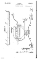
- z. is the engine, 'i the dash-board, y' another device to be protected, for example, a gasoline pump. Between 1l and 12 the connection is provided by the cord. Within its From 13 to lli the cord is once more found' in its sheath and at y' the arrangement likewise comprises a fuse if" and the tightener c. As a result of that arrangement the position of such devices as i, l1., j may vary under the influence of external reaction without bringing about any disturbance in the satisfactory operation of the warning means.
- the arran ement comprises a dynamometer 1', shown in 1 ig. 9 in the rst bracket.
- a device for controlling the operation of fire extinguishers or other objects to be operated comprising a housing embodying juxtaposed main and auxiliary compartments having an opening connecting them; a ball movable in either direction through saidopening; a member slidable in the main compartment and formed with a circumferential groove to normally receive the ball and be.
- said member adapted to be operatively connected to the object to be operated; an operating spring acting axially on one end of said member to operate said object; a member slidable in the auxiliary compartment and formed With a depression to receive the ball when the latter moves thereinto through said opening; a spring tending to move said member into a position whereby the depression receives the ball; a fuse; a flexible connection between the fuse and the secondnamed sliding member to hold that member against the action of its spring, said secondnamed member being released by the melting of the fuse permitting the consequent movement of the ball into said depression, thereby to release the first-named member and operate the object connected to the same; and means for indicating the melting of the fuse.
- the means for indicating the melting of the fuse comprises a normally-concealed member which is brought automatically into visible position by the movement of the member slidable in the auxiliary compartment consei quent upon the melting of the fuse.
- a device for controlling the operation of tire extinguishers or other objects to be operated comprising a housing embodying juxtaposed main and auxiliary compartments having an opening connecting them; a. ball movable in either direction through said opening; a member slidable in the main compartment and formed with a circumferential groove to normally receive the ball and be locked thereby against endwise movement, said member adapted to be operatively connected to the object to be operated; an
Landscapes
- Health & Medical Sciences (AREA)
- Public Health (AREA)
- Business, Economics & Management (AREA)
- Emergency Management (AREA)
- Safety Valves (AREA)
Description
May 3, 1932- J. MARTIN FIRE EXTINGUISHER Filed Dec. 13 1928 3 Sheets-Sheet FMS/BLE JU /v /VA//e r//v J. MARTIN FIRE EXTINGUISHER May 3, 1932.
'Filed Dec. 13 1928 3 SheecS-Sheel'I 2 -iszaarszzp y'Il'IIIIIIII'IIIIIIIIIIIIA l l l l l l l l I l l l l l Il I l //7 Vm ro@ rfeam Marn@ I9/ Mfg 47m/ffy J. MARTIN FIRE EXTINGUISHER Filed Dec. l5 1928 3 Sheets-Sheet 3 May 3.,'1932.
Patented May 3, 1932 A UNITED STAT-Es .PATENT ,OFFICE y JEAN MARTIN, OF ST. .UEN, FRANCE FIRE EXTINGUISHER Application led Decemb'i'enl, 1928, Serial No. 325,873, and in France December 16, 1927.
This invention has for .its object adevice for thel remote control of re extinguishers, particularly on board of airplanes or other flying machines and, generally, on board of vehicles or in plants where a re is likely to break out. y
The improved device is arranged in such manner that the release of the extinguisher may take place:
(xa) Either automatically, through the me ting of one or more fuses, under the action of a rise in temperature; or
- (b) Directly by hand, without, however, releasing the above automatic operating mechanism. A spring release device allows,
' alternatively, to stop the lire extinguisher, and to set it again in operation, whether the release thereof occurred automatically or by hand.
Moreover, the invention covers an embodiment of a particular method of mounting the fuses. The appended drawings show, by way of example, an embodiment-of the control device, the general features of which have just been given.
Figure 1 is a longitudinal sectional view of said control device;
Fig. 2 a vertical section of a lire extinguisher of known type actuated by the said device;
Fig. 3 is a side view of a fuse used in connection with the device in question;
Fig. 4 is a face view of an indicator plate forming part of the controller;
Fig. 5 is an enlarged plan view of the above-mentioned fuse;
Fig. 6 is a diagrammatic view of another form of fuse, and
Figs. 7, 8 and 9 show various ways of mounting the fuses.
It is to be understood at theoutset that the controller illustrated in Fig. 1 operates automatically in connection with the fuse mecha- 'i nism or device represented in Fig. 3, and itself operates to actuate the tire extinguisher shown in Fig. 2: it being assumed that the Bowden connection of Fig. 2 forms part of the connection J of Fig. 1 and, in like manner, the Bowden connection I also forms part of the connectionshown in Fig. 3. The ,connections in question are assumed to be of indefinite length, the control portions thereof being broken away; but in practice the two parts indicated in Figs. 1 and 2 will be bridged or united, and the same with respect ofthe two parts indicated in Figs. 1 and 3.
As to the fire extinguisher, which is generally designated X, this element or device, as already stated, is of known type and operates in known manner, and it forms, in itself, no part of the actual invention, so that its structural details are immaterial and need not be described. It is believed to be sulii cient tor all present purposes, that when the controller is actuated either automatically or by hand, in the manner hereinafter explained, the action thereby exerted upon the aforesaid Bowden connection J (Fig. l), will be transmitted to the controlling lever X ofthe extinguisher X and will actuate the same.
It must be understood, moreover, that while the improved controller is designed primarily for application vto a fire extinguisher of suitable type, that is not its only use. In place of being applied to a fire extinguisher, it can be connected with other apparatus or devices to be operated consequent upon an abnormal temperature-rise.
The control device comprises a tubular, e. g. cvlindrical body A (Fig. 1) in which is movably housed a piston provided with a frusto-conical portion C', having a reduced portion Y forming a shoulder C, against which rests one end of a helical spring E, the other end of which rests against the bottom of a tubular part A screwed to member A. This spring surrounds the cylindrical part Y above mentioned. The portion C is also formed with a flattened surface or part K which may be brought into registering relation with ball D by turning piston B about its axis. f
lfnto groove C projects a ball D which prevents spring E from expanding when piston B is cocked-that is, is subjected to the action -ot said spring. This ball is maintained in its position in groove C by the action of an auxiliary piston F working in an additional Oil hollow cylinder G at the side of and communicating with cylinder A.. Said piston F, which is under the action of a spring H, is provided with a groove 2 which permits the i all to move from groove C into groove 2 The initial position of operation (automatic, manual or stop) is controlled by al handle L and a bayonet joint, the slot of which is located in the fixed body A, while the pin M is secured to the piston B. The said pin M carries a pointer N which `moves in front of an indicating plate formed by the rir'n Z of body A and bearing the words Start, Stop and Norma-l. Moreover, in a seat or opening provided in plate Z is a disk O which is normally kept concealed by a movable member P that is dislodged by the piston F when the fuse melts. The shutter P is hinged to the body A. and is kept closed in.normal position by means of a spring or wedge member. In the active position, when the fuses melt, the piston dislodges the shutter P against the force of the spring or the wedge member and brings the disk O into view; When the members are replaced into rest position, the fuses are replaced and the piston F goes back to its original-position.
- The shutter P is then returned either by the spring or manually by hand and kept in place by means of the wedge member.
It will be assumed that the apparatus is in its inactive or unset position. The springs E and H are expanded and piston B is in projected position, point l of said piston lying to 011e side of ball D while point 2 of piston F lies to the other side of said ball. In order to set said apparatus, the handle L is pushed right in, then turned until finger N stands in front of the word Stop, on the rim or plate Z. At that time, spring E is compressed and held -in its position; and pin M is at position 3 (Fig. 4) in the locking slot. Spring- H is then compressed by fitting the fuses on cord I, and the device is then set in the position shown in Fig. 1. The handle L is then turned so as to bring finger N in front of the word Normal and the locking pin is then `at 4 (Fig. 4), the apparatus being then ready for operation. The fuses used may be of different kinds and arranged at suitable points and connected to a cord I which maintains spring H under compression; the operation of each fuse being` based on the relative displacement of two members.
In the form represented in Figs. 3 and 5,
these members consist of slidablyy connected links U and U to which cord I is attached, which are normally fastened together by a drop of solder V (Fig. 5) while in Fig. 6, they comprise a cylinder R and a piston S connected to the cord I. The cylinder R contains a body of solder T which prevents the outward movement of piston S, while the solder retains its solid state, at normal temperature, and resists the compression. strain to which it is subjected by the tension of cord I through reaction upon the cylinder and pist-on. ture, the body T melts and fiows away through the clearances provided in the appartus, which allows of a relative displacement of the constituent parts R and S. The operation of bot-h devices is substantially the same, as will be understood, and involves only very weak tensions on the traction cords. Moreover, by varying the composition of the body T it is possible to obtain a 'comparatively wide range of operation points. On the other hand, the very nature of such compound renders the fire extinguisher extremely sensitive to rises of temperature and insures a high degree of safety in operation.
Automatic operation As a result of a rise in tempera- A from without. The point 2 lies to one side of ball D which, being released, is thrown out of groove C by the release of spring E. This movement involves that of piston B which exerts on the cord a pull by which. the fire extinguisher is made to operate.
Dif/'ect hand control The apparatus being in the position shown in Fig. l, the pin M which stood in front of the word Normal merely has to be brought in front of the word Start. The result of such displacement of piston B' is to bring the flat portion K thereof in registering relation to ball D, so that said piston is free to move backwards under the action of spring E without involving the displacement of ball D.
In the above considerations it has been shown that the melting point of the fuses depends on:
(l) The composition,
(2 Thetemperature,
(3) The strain to which they are subelements F. At a is the control device, and is another fixed point of the arrangement where the line terminates in a tightener c.
If, by construction, points L and b are invariable in their positions, it is merely necessary rto give proper tension to cord d; as the points of reaction aand Z) are lixed, the tension of the cord will remain constant.
If the position of these points happens to vary, the result will be a tightening or a slackening of the cord, andthe melting point of the fuse will be varied accordingly within wide limits. y
In practice, and particularly in arrangements on board flying machines, or in connection with any other power system provided with a .propelling member, it is not possible to obtain a constant tension of the cord on account of the deformation of the whole system resulting from external reactions.
According to this invention, a remote con- `trolling means connecting all the fuses together has thus been provided which maintains a constant pull on the latter.
Fig. 9 shows, by way of example, an embodiment of one such means. It comprises .a number of rigid brackets e adapted to receive fuses'F. One of these brackets is located at the end of the fuse line and is provided with a tightener c.
At the other end the line leads to a bracket f which receives the control device L. Thel connection between the various fuses is provided by means of a cord leading from a to c and slidable between the brackets within a 4. In the construction shown in 8, which is designed for use on board an airplane, the points a and b maybe moved with respect to eachother without varying the tension of the cord wit-hin the sheath.- The pull of the cord is applied to points a and b whereof the interconnection providing for the reaction of the system is obtained in the following manner (see Fig. 9)
' From 1 to 2 through the outer sheath; from D 2 to 3 through the bracket; from 3 to 4 through the outer sheath from 4 to 5 through the bracket; from 5 to 6 through the outer sheath; from 6 to 7 through the bracket.
It follows that the brackets may be displacedwith respect to one another without thereby altering the tension of the cord.
In Fig. 8, z. is the engine, 'i the dash-board, y' another device to be protected, for example, a gasoline pump. Between 1l and 12 the connection is provided by the cord. within its From 13 to lli the cord is once more found' in its sheath and at y' the arrangement likewise comprises a fuse if" and the tightener c. As a result of that arrangement the position of such devices as i, l1., j may vary under the influence of external reaction without bringing about any disturbance in the satisfactory operation of the warning means.
Where the tension of the cord must be regulated very closely, the arran ement comprises a dynamometer 1', shown in 1 ig. 9 in the rst bracket.
I lclaim as my invention:
1. A device for controlling the operation of lire extinguishers or other objects to be operated, comprising a housing embodying juxtaposed main and auxiliary compartments having an opening connecting them; a ball movable in either direction through saidopening; a member slidable in the main compartment and formed with a circumferential groove to normally receive the ball and be. locked thereby against endwise movement, said member adapted to be operatively connected to the object to be operated; an operating spring acting axially on one end of said member to operate said object; a member slidable in the auxiliary compartment and formed With a depression to receive the ball when the latter moves thereinto through said opening; a spring tending to move said member into a position whereby the depression receives the ball; a fuse; a flexible connection between the fuse and the secondnamed sliding member to hold that member against the action of its spring, said secondnamed member being released by the melting of the fuse permitting the consequent movement of the ball into said depression, thereby to release the first-named member and operate the object connected to the same; and means for indicating the melting of the fuse.
2. A device according to claim 1, in which the means for indicating the melting of the fuse comprises a normally-concealed member which is brought automatically into visible position by the movement of the member slidable in the auxiliary compartment consei quent upon the melting of the fuse.
3. A device for controlling the operation of tire extinguishers or other objects to be operated, comprising a housing embodying juxtaposed main and auxiliary compartments having an opening connecting them; a. ball movable in either direction through said opening; a member slidable in the main compartment and formed with a circumferential groove to normally receive the ball and be locked thereby against endwise movement, said member adapted to be operatively connected to the object to be operated; an
operating spring acting on said member; a spring-actuated member endable 1n the auxiliary compartment and formed with a depression to receive vthe ball when the latter moves thereinto through said opening; a flexible fuse line connected Withrthe secondnamed sliding member and having a plurality of separate fuses included therein at points which are displaceable With respect to,
the same.
JEAN MARTIN.
Applications Claiming Priority (1)
| Application Number | Priority Date | Filing Date | Title |
|---|---|---|---|
| FR1856575X | 1927-12-16 |
Publications (1)
| Publication Number | Publication Date |
|---|---|
| US1856575A true US1856575A (en) | 1932-05-03 |
Family
ID=9681709
Family Applications (1)
| Application Number | Title | Priority Date | Filing Date |
|---|---|---|---|
| US325873A Expired - Lifetime US1856575A (en) | 1927-12-16 | 1928-12-13 | Fire extinguisher |
Country Status (1)
| Country | Link |
|---|---|
| US (1) | US1856575A (en) |
Cited By (2)
| Publication number | Priority date | Publication date | Assignee | Title |
|---|---|---|---|---|
| US4383579A (en) * | 1980-05-22 | 1983-05-17 | Monk Guerdon M | Shock actuated fire prevention system for automobiles |
| US20080210443A1 (en) * | 2007-03-02 | 2008-09-04 | Michael Walter Erva | Fire Suppression System and Emergency Annunciation System |
-
1928
- 1928-12-13 US US325873A patent/US1856575A/en not_active Expired - Lifetime
Cited By (4)
| Publication number | Priority date | Publication date | Assignee | Title |
|---|---|---|---|---|
| US4383579A (en) * | 1980-05-22 | 1983-05-17 | Monk Guerdon M | Shock actuated fire prevention system for automobiles |
| US20080210443A1 (en) * | 2007-03-02 | 2008-09-04 | Michael Walter Erva | Fire Suppression System and Emergency Annunciation System |
| US9352176B2 (en) | 2007-03-02 | 2016-05-31 | Tyco Fire Products Lp | Fire suppression system and emergency annunciation system |
| US10398916B2 (en) | 2007-03-02 | 2019-09-03 | Tyco Fire Products Lp | Fire suppression system and emergency annunciation system |
Similar Documents
| Publication | Publication Date | Title |
|---|---|---|
| US2650655A (en) | Multidirectional inertia-operated safety device for vehicle chairs | |
| US4015860A (en) | Vehicle seat safety harness | |
| US4434953A (en) | Dual spool pretensioner | |
| US3522918A (en) | Safety harness device | |
| US2927473A (en) | Electric actuators | |
| US3949623A (en) | Steering column assembly | |
| US1856575A (en) | Fire extinguisher | |
| US2399553A (en) | Aircraft fire extinguishing system | |
| US815137A (en) | Safety starting mechanism for motors. | |
| US3992999A (en) | Controlled actuator | |
| US4245660A (en) | Manual override for short stroke valve | |
| US4265316A (en) | Fire extinguishing system having a linkage operated valve | |
| US3096957A (en) | Ballistic rotary actuator | |
| JP6306534B2 (en) | Webbing take-up device | |
| US3215376A (en) | Aircraft ejection seats | |
| US811440A (en) | Block. | |
| US1254982A (en) | Controlling device. | |
| US2828997A (en) | Delay release for parachutes | |
| US1072841A (en) | Automatic safety-brake for automobiles. | |
| SU624645A1 (en) | Pyromechanical valve for automatic fire-fighting systems | |
| US1421774A (en) | Pressure gauge | |
| US1080900A (en) | Engine-starting mechanism. | |
| US1433269A (en) | Automobile lock | |
| US1319153A (en) | Planooraph co | |
| US1250552A (en) | Safety means for gas-tanks. |