US1856574A - Aligning device - Google Patents
Aligning device Download PDFInfo
- Publication number
- US1856574A US1856574A US529756A US52975631A US1856574A US 1856574 A US1856574 A US 1856574A US 529756 A US529756 A US 529756A US 52975631 A US52975631 A US 52975631A US 1856574 A US1856574 A US 1856574A
- Authority
- US
- United States
- Prior art keywords
- brick
- pallet
- conveyor
- members
- pallets
- Prior art date
- Legal status (The legal status is an assumption and is not a legal conclusion. Google has not performed a legal analysis and makes no representation as to the accuracy of the status listed.)
- Expired - Lifetime
Links
- 239000011449 brick Substances 0.000 description 37
- 238000007688 edging Methods 0.000 description 5
- XEEYBQQBJWHFJM-UHFFFAOYSA-N Iron Chemical compound [Fe] XEEYBQQBJWHFJM-UHFFFAOYSA-N 0.000 description 2
- 241000239290 Araneae Species 0.000 description 1
- 229910000831 Steel Inorganic materials 0.000 description 1
- 238000010276 construction Methods 0.000 description 1
- 229910052742 iron Inorganic materials 0.000 description 1
- 238000004519 manufacturing process Methods 0.000 description 1
- 238000000034 method Methods 0.000 description 1
- 239000010959 steel Substances 0.000 description 1
Images
Classifications
-
- B—PERFORMING OPERATIONS; TRANSPORTING
- B65—CONVEYING; PACKING; STORING; HANDLING THIN OR FILAMENTARY MATERIAL
- B65G—TRANSPORT OR STORAGE DEVICES, e.g. CONVEYORS FOR LOADING OR TIPPING, SHOP CONVEYOR SYSTEMS OR PNEUMATIC TUBE CONVEYORS
- B65G47/00—Article or material-handling devices associated with conveyors; Methods employing such devices
- B65G47/22—Devices influencing the relative position or the attitude of articles during transit by conveyors
- B65G47/26—Devices influencing the relative position or the attitude of articles during transit by conveyors arranging the articles, e.g. varying spacing between individual articles
- B65G47/28—Devices influencing the relative position or the attitude of articles during transit by conveyors arranging the articles, e.g. varying spacing between individual articles during transit by a single conveyor
- B65G47/29—Devices influencing the relative position or the attitude of articles during transit by conveyors arranging the articles, e.g. varying spacing between individual articles during transit by a single conveyor by temporarily stopping movement
-
- B—PERFORMING OPERATIONS; TRANSPORTING
- B65—CONVEYING; PACKING; STORING; HANDLING THIN OR FILAMENTARY MATERIAL
- B65G—TRANSPORT OR STORAGE DEVICES, e.g. CONVEYORS FOR LOADING OR TIPPING, SHOP CONVEYOR SYSTEMS OR PNEUMATIC TUBE CONVEYORS
- B65G17/00—Conveyors having an endless traction element, e.g. a chain, transmitting movement to a continuous or substantially-continuous load-carrying surface or to a series of individual load-carriers; Endless-chain conveyors in which the chains form the load-carrying surface
- B65G17/002—Conveyors having an endless traction element, e.g. a chain, transmitting movement to a continuous or substantially-continuous load-carrying surface or to a series of individual load-carriers; Endless-chain conveyors in which the chains form the load-carrying surface comprising load carriers resting on the traction element
-
- B—PERFORMING OPERATIONS; TRANSPORTING
- B65—CONVEYING; PACKING; STORING; HANDLING THIN OR FILAMENTARY MATERIAL
- B65G—TRANSPORT OR STORAGE DEVICES, e.g. CONVEYORS FOR LOADING OR TIPPING, SHOP CONVEYOR SYSTEMS OR PNEUMATIC TUBE CONVEYORS
- B65G47/00—Article or material-handling devices associated with conveyors; Methods employing such devices
- B65G47/22—Devices influencing the relative position or the attitude of articles during transit by conveyors
-
- B—PERFORMING OPERATIONS; TRANSPORTING
- B65—CONVEYING; PACKING; STORING; HANDLING THIN OR FILAMENTARY MATERIAL
- B65G—TRANSPORT OR STORAGE DEVICES, e.g. CONVEYORS FOR LOADING OR TIPPING, SHOP CONVEYOR SYSTEMS OR PNEUMATIC TUBE CONVEYORS
- B65G2201/00—Indexing codes relating to handling devices, e.g. conveyors, characterised by the type of product or load being conveyed or handled
- B65G2201/02—Articles
- B65G2201/0235—Containers
- B65G2201/0258—Trays, totes or bins
-
- B—PERFORMING OPERATIONS; TRANSPORTING
- B65—CONVEYING; PACKING; STORING; HANDLING THIN OR FILAMENTARY MATERIAL
- B65G—TRANSPORT OR STORAGE DEVICES, e.g. CONVEYORS FOR LOADING OR TIPPING, SHOP CONVEYOR SYSTEMS OR PNEUMATIC TUBE CONVEYORS
- B65G2201/00—Indexing codes relating to handling devices, e.g. conveyors, characterised by the type of product or load being conveyed or handled
- B65G2201/02—Articles
- B65G2201/0267—Pallets
Definitions
- Serial This invention relates to an aligning device adapted to receive a plurality of articles irregularly placed upon a pallet or similar support in turn being transported 'upon a conveyor and to align said articles upon said pallet in a predetermined relationship during, transit.
- This application is a division of application Serial No. 400,835, filed Ootober 19, 1929, which is in turn a continuation in part of application Serial No. 237,191, filed December 2, 1927, the latter application having resulted in Patent No. 1,746,664 issued February 11, 1930.
- the brick are formed in a mold and placed in the soft condition on steel pallets with their largest surface in contact with the pallet. The brick are then dried without being removed from the pallet.
- the pallets carrying the brick are'transported from the drier by a chain conveyor. The pallets are accurately positionedupon the conveyor and the brick accurately centered upon the pal- A lets by means of a centering device which is the subject of prior patent of Grafton E. Luce and Thomas B. Huestis, No. 1,820,471,
- the object of the present invention is to provide appara'tus which aligns the brick on the pallet in a line transverse to the line of travel thereof and in the proper position to be engagedjby'the edging machine.
- the said apparatus is of course equally useful in aligning other articles upon a conveyor for other purposes than that herein disclosed.
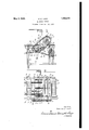
- Figure 1 is an elevational view of the apparatus and Figure 2 is a plan view thereof.
- a framework for supporting the machine is provided and includes a plurality of vertical columns 10, horizontal beams 11 supported upon the upper ends thereof, horizontal members 12 attached adjacent the lower ends of the said columns and suitable cross bracing between the columns 10 and between the members 11 not shown in the drawings.
- a horizontal shaft 13 is supported upon bearings 14 in turn supported upon the frame members 11 and carries three sprockets 15 and two sprockets 16.
- a pair of conveyor chains 17 are'trained about the sprockets 16 andare adapted to deliver the pallets 18 carrying brick 19 from the centering device previously mentioned to the aligning device.
- Three conveyor chains 24 are trained about the sprockets 15 and other suitable sprockets not shown.
- the said chains receive the pallets from the chains 17 and convey the same to the edging machine. They maybe driven by any suitable means such as an electric motor.
- the sprockets 15 and 16 are all keyed to shaft 13'so that movement of chains 24 ment of chains 17.
- Each of the outer conveyor chains 24 carries a plurality of attachments 26 which project upwardly into thepath of travel of the pallet.
- the pallets When discharged from the centering device which is the subject of the beforemenfionedzPatent No. 1,820,471, the pallets have been accurately centered upon the conproduces a like move- 7 veyor chains 17, and the brick have been lets reach the conveyor chains 24 at the propcentered upon the pallet and positioned with their edges in contact. The forward and rear edges of adjacent brick, however, have not been aligned with each other.
- the brick
- the pallets are released from the centeringdevice in timed relation with the travel of. the conveyor 17. This relation is such that'the paler time to position each pallet immediately ahead of a pair of the attachments 26.
- an aligning Wheel is providedcons stingof horizontally disposed angle members 27 supported upon spiders 28 in turn fixedly carried upon a shaft 29.
- the shaft 29 is supported upon A-frames 30 carried upon the frame members 11..
- a sprocket 31 is carried upon one end of the .shaft 29.
- a shaft .32 is supported upon bearings 33 carried upon the frame members 11 and is rotated by means of a pair of spur gears34r and 35 carried upon the said shaft and. upon the shaft 13 respectively.
- a sprocket 36 is carried upon the shaft 32 and a sprocket chain 37 is trained about the saidsprocket-and the sprocket 31;
- a takeup 38 is provided for takingiip wear in the sprocket chains 37.
- Each of the members 27 is timed to reach itsilowermost .7 position at the propertim'eto engage the front edge of the brick carried upon a pallet.
- a conveyor adapted to transporta pluralityof pallets in a predetermined spaced relation, each pallet having arplura'lity of brick thereon, and an aligning, wheel operable in timed relation with the travel of said conveyor and having members thereon adapted to engage the front edges of said brick formoving the'brick to the rear of the pallet'and simultaneously aligning thevsaine-transversely tothe line of travel.
Landscapes
- Engineering & Computer Science (AREA)
- Mechanical Engineering (AREA)
- Intermediate Stations On Conveyors (AREA)
Description
May 3, 1932. G. E. LUCE 1,856,574
ALIGNING DEVICE 1 Original Filed Oct. 19, 1929 INVENTOR. GKHFTO/Y L. A ucf.
K m Kiw W m!- ATTORNEYS.
Patented May 3, 1932 urrsn STATES PATENT OFFICE GRAFTON E. LUCE, OF CHICAGO, ILLINOIS ASSIGNOB TO LANCASTER IRON WORKS, INC., OF LANCASTER, PENNSYLVANIA, A CORPORATION ALIGNING DEVICE Original application filed October 19, 1929, Serial N0. 400,835. Divided and this application filed April 13,
1931. Serial This invention relates to an aligning device adapted to receive a plurality of articles irregularly placed upon a pallet or similar support in turn being transported 'upon a conveyor and to align said articles upon said pallet in a predetermined relationship during, transit. This application is a division of application Serial No. 400,835, filed Ootober 19, 1929, which is in turn a continuation in part of application Serial No. 237,191, filed December 2, 1927, the latter application having resulted in Patent No. 1,746,664 issued February 11, 1930.
In the manufacture of brick by the socalled soft mud process, the brick are formed in a mold and placed in the soft condition on steel pallets with their largest surface in contact with the pallet. The brick are then dried without being removed from the pallet. In the mechanical handling of brick between the drier and the kiln, the pallets carrying the brick are'transported from the drier by a chain conveyor. The pallets are accurately positionedupon the conveyor and the brick accurately centered upon the pal- A lets by means of a centering device which is the subject of prior patent of Grafton E. Luce and Thomas B. Huestis, No. 1,820,471,
1 issued August 25, 1931. The pallets and brick are then delivered to the aligning device which is hereinafter described and by means of which the brick are aligned in the proper position upon the pallet to be acted upon by the edging machine which forms the subject matter of application Serial No. 400,835 mentioned above. By means there- 'of the brick on the pallet are turned up on edge and grouped in the proper relation for further handling. From the edging machine the brick are conveyed to a hacking machine of the general type disclosed in Patent No. 1,627 ,656, issued to Grafton E. Luce May 10, 1927. The hacking machine removes the brick from the pallet and stacks them in a unit stack on a kiln car in the proper relation for burning. The car and brick are then transported to the kiln shed and the brick are set in place for burning by means of a brick setter of the general type disclosed in Patent No. 1,205,562, issued to B. C. Pen
field November 21, 1916, and Patent No. 1,712,773, issued to Grafton E. Luce May 14, 1929. r
The object of the present invention is to provide appara'tus which aligns the brick on the pallet in a line transverse to the line of travel thereof and in the proper position to be engagedjby'the edging machine. The said apparatus is of course equally useful in aligning other articles upon a conveyor for other purposes than that herein disclosed.
The specific features of the invention by which this object is attained will be apparent from the accompanying drawings and the following description and claims:
Figure 1 is an elevational view of the apparatus and Figure 2 is a plan view thereof. A framework for supporting the machine is provided and includes a plurality of vertical columns 10, horizontal beams 11 supported upon the upper ends thereof, horizontal members 12 attached adjacent the lower ends of the said columns and suitable cross bracing between the columns 10 and between the members 11 not shown in the drawings. A horizontal shaft 13 is supported upon bearings 14 in turn supported upon the frame members 11 and carries three sprockets 15 and two sprockets 16. A pair of conveyor chains 17 are'trained about the sprockets 16 andare adapted to deliver the pallets 18 carrying brick 19 from the centering device previously mentioned to the aligning device. Three conveyor chains 24 are trained about the sprockets 15 and other suitable sprockets not shown. The said chains receive the pallets from the chains 17 and convey the same to the edging machine. They maybe driven by any suitable means such as an electric motor. The sprockets 15 and 16 are all keyed to shaft 13'so that movement of chains 24 ment of chains 17.
Each of the outer conveyor chains 24 carries a plurality of attachments 26 which project upwardly into thepath of travel of the pallet. When discharged from the centering device which is the subject of the beforemenfionedzPatent No. 1,820,471, the pallets have been accurately centered upon the conproduces a like move- 7 veyor chains 17, and the brick have been lets reach the conveyor chains 24 at the propcentered upon the pallet and positioned with their edges in contact. The forward and rear edges of adjacent brick, however, have not been aligned with each other. The brick,
therefore, may be in the relation illustrated in the left of Figure2. As described in the before-mentioned issued patent, the pallets are released from the centeringdevice in timed relation with the travel of. the conveyor 17. This relation is such that'the paler time to position each pallet immediately ahead of a pair of the attachments 26.
' For aligning the forward edges of the brick, an aligning Wheel is providedcons stingof horizontally disposed angle members 27 supported upon spiders 28 in turn fixedly carried upon a shaft 29. The shaft 29 is supported upon A-frames 30 carried upon the frame members 11.. A sprocket 31 is carried upon one end of the .shaft 29. A shaft .32 is supported upon bearings 33 carried upon the frame members 11 and is rotated by means of a pair of spur gears34r and 35 carried upon the said shaft and. upon the shaft 13 respectively. A sprocket 36 is carried upon the shaft 32 and a sprocket chain 37 is trained about the saidsprocket-and the sprocket 31; A takeup 38 is provided for takingiip wear in the sprocket chains 37.
' "By means of this construction, the aligning wheel isrotated-in the direction indicated by an arrow in Figure l. The ratio of the gears 34 and 35'and the various sprocket sizes are selected to drive the outer edges of the horizontal members 27 of'the aligning.
' wheelat' 'a speed slightly slower than the speed ofthe conveyor chains 24. Each of the members 27 is timed to reach itsilowermost .7 position at the propertim'eto engage the front edge of the brick carried upon a pallet.
Since the members 27. are travelling at a slower speed than the chains 24. this engage- 7 ment results in sliding the brick back on the pallet and sliding the pallet backward upon the chain until the pallet'strikes the attachment 26. In the further travel ofthe pallet and the members 27 the said members are elevated from the path of the brick leaving the brick al gned upon the pallet with their rear edges'substantiallv in line with the rear edges-of the pallet an d leaving the front ed ge of. the palletclear. The final'po'sition of the brickunon the pallet is shown by pallet 18 and-brick 19 at the right-in Figure 2'. In this'position they maybe actedupon bv'the edging machine as described in the beforement oned a plication. Serial No. 00,835. The invention claimed is: i
' 1. The'combination of a conveyor adapted to transport a plurality ofpallets each having a plurality of brick thereon, a movable member movable through a portion of its movement being at a slower rate of speed than the movement of said conveyor whereby engagement of said brick with said movable member repositions said brick relatively of said pallet, and means on said conveyor for preventing relative movement between'said palletsand conveyor during said engagement. I
2. The combinationof a conveyor adapted to transporta pluralityof pallets in a predetermined spaced relation, each pallet having arplura'lity of brick thereon, and an aligning, wheel operable in timed relation with the travel of said conveyor and having members thereon adapted to engage the front edges of said brick formoving the'brick to the rear of the pallet'and simultaneously aligning thevsaine-transversely tothe line of travel.
3. The combination of a conveyor adapted to transport a plurality of pallets each having aplurality of brick thereon, attachments on said conveyor adaptedto serve as'abutments for said pallets, a rotatable aligning wheel having members thereon. movable through a portion of their travel in the path of travel of said brick, and mechanism for rotating said wheel to move said members in timed relation to the movement of said conveyor'and at a speed slower than said conveyor movement whereby each of said members engages thefront edges ofthe brick on one'of said pallets to retard the movement of brick and pallet until the pallet isengaged by one of said" attachments and thereafter to retard the movement of the brick alone until. the same are aligned upon said pallet.
" In Witness whereof, I have hereunto llfiXQCl my signature, 1 GRAFTON E. LUC-E.
travel in the path oftravel of said brick, said A
Priority Applications (1)
| Application Number | Priority Date | Filing Date | Title |
|---|---|---|---|
| US529756A US1856574A (en) | 1929-10-19 | 1931-04-13 | Aligning device |
Applications Claiming Priority (2)
| Application Number | Priority Date | Filing Date | Title |
|---|---|---|---|
| US400835A US1905477A (en) | 1929-10-19 | 1929-10-19 | Brick edging machine |
| US529756A US1856574A (en) | 1929-10-19 | 1931-04-13 | Aligning device |
Publications (1)
| Publication Number | Publication Date |
|---|---|
| US1856574A true US1856574A (en) | 1932-05-03 |
Family
ID=27017206
Family Applications (1)
| Application Number | Title | Priority Date | Filing Date |
|---|---|---|---|
| US529756A Expired - Lifetime US1856574A (en) | 1929-10-19 | 1931-04-13 | Aligning device |
Country Status (1)
| Country | Link |
|---|---|
| US (1) | US1856574A (en) |
Cited By (1)
| Publication number | Priority date | Publication date | Assignee | Title |
|---|---|---|---|---|
| DE1232521B (en) * | 1964-08-24 | 1967-01-12 | Gebhardt G M B H | Device for dispensing and orderly depositing objects transported on a continuous conveyor |
-
1931
- 1931-04-13 US US529756A patent/US1856574A/en not_active Expired - Lifetime
Cited By (1)
| Publication number | Priority date | Publication date | Assignee | Title |
|---|---|---|---|---|
| DE1232521B (en) * | 1964-08-24 | 1967-01-12 | Gebhardt G M B H | Device for dispensing and orderly depositing objects transported on a continuous conveyor |
Similar Documents
| Publication | Publication Date | Title |
|---|---|---|
| US1556695A (en) | Sheet and plate piling device | |
| US2363189A (en) | Container separating apparatus | |
| US2684147A (en) | Can unscrambling machine | |
| US1535785A (en) | Chain curve | |
| US1856574A (en) | Aligning device | |
| US1733221A (en) | Pallet squaring and aligning device | |
| US2501473A (en) | Article transfer mechanism for pallet conveyers | |
| US4273236A (en) | Method and apparatus for handling bottles | |
| US1444999A (en) | Magnetic conveyer | |
| US3604554A (en) | Tray-spacing conveyor | |
| US1905477A (en) | Brick edging machine | |
| GB1473721A (en) | Conveyors | |
| US2530419A (en) | Can unscrambler | |
| US2464334A (en) | Leer loader | |
| US2466962A (en) | Article conveying and distributing mechanism | |
| US2370188A (en) | Can uprighting device | |
| US1516409A (en) | Apparatus for automatically switching brick into plurality of rows for unit formation | |
| US1869210A (en) | Automatic unloader for driers | |
| US1389887A (en) | Machine for cooling chocolates and the like | |
| US1491771A (en) | Loading and unloading apparatus | |
| US3592328A (en) | Transfer and orienting mechanism for articles | |
| US2865490A (en) | Single filing machine | |
| GB2037245A (en) | A roller conveyor | |
| US2017046A (en) | Doughproofing machine | |
| US2253529A (en) | Apparatus for handling sheet material |