US1856573A - Stoker - Google Patents
Stoker Download PDFInfo
- Publication number
- US1856573A US1856573A US206887A US20688727A US1856573A US 1856573 A US1856573 A US 1856573A US 206887 A US206887 A US 206887A US 20688727 A US20688727 A US 20688727A US 1856573 A US1856573 A US 1856573A
- Authority
- US
- United States
- Prior art keywords
- trough
- conduit
- section
- fuel
- crusher
- Prior art date
- Legal status (The legal status is an assumption and is not a legal conclusion. Google has not performed a legal analysis and makes no representation as to the accuracy of the status listed.)
- Expired - Lifetime
Links
- 239000000446 fuel Substances 0.000 description 13
- 238000005266 casting Methods 0.000 description 8
- 238000010276 construction Methods 0.000 description 4
- 230000003137 locomotive effect Effects 0.000 description 4
- 239000002184 metal Substances 0.000 description 4
- 238000004873 anchoring Methods 0.000 description 2
- 239000003245 coal Substances 0.000 description 2
- 238000009434 installation Methods 0.000 description 2
- 238000004519 manufacturing process Methods 0.000 description 2
- 230000003014 reinforcing effect Effects 0.000 description 2
- 229910001208 Crucible steel Inorganic materials 0.000 description 1
- 229910000831 Steel Inorganic materials 0.000 description 1
- CEJLBZWIKQJOAT-UHFFFAOYSA-N dichloroisocyanuric acid Chemical compound ClN1C(=O)NC(=O)N(Cl)C1=O CEJLBZWIKQJOAT-UHFFFAOYSA-N 0.000 description 1
- 239000010959 steel Substances 0.000 description 1
- 238000005728 strengthening Methods 0.000 description 1
Images

Classifications
-
- F—MECHANICAL ENGINEERING; LIGHTING; HEATING; WEAPONS; BLASTING
- F23—COMBUSTION APPARATUS; COMBUSTION PROCESSES
- F23K—FEEDING FUEL TO COMBUSTION APPARATUS
- F23K3/00—Feeding or distributing of lump or pulverulent fuel to combustion apparatus
- F23K3/04—Feeding or distributing of lump or pulverulent fuel to combustion apparatus for locomotive boiler furnaces
Definitions
- a further object of the invention is the lprovision of a new and improved means for receiving the fuel from the tender and transferring the same to the locomotive.
- Another object of the invention is the provision of a detachable ⁇ crusher whereby the same may be attached at any point along the trough, thereby permttillig the troughs to be
- a still further object of the invention is the provision of new and improved conveyor trough or conduit that is rigid in construction, cheap to manufacture, easily attached in osition, strong, durable, well reinforced, and) that is not likely to become broken, distorted or get out of order.
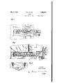
- FIG. 1 is a vertical section of a portion of a locomotive and its tender showing the invention in position thereon, with parts in section and parts broken away;
- Fig. 2 is a bottom plan view of a tender showing the invention in position thereon
- Fig. 3 is asection on line 3-3 of Fig. 1;
- Fig. 4 is a section on line 4 4 of Fig.1;
- the conveyor trough or conduit is usually substantially V-shape in cross-section in one portion and U-shape or cylindrical at another portion, and comprises two sheets bent to these two forms and connected together by 'a suitable casting which is riveted to the adjacent ends of the two sheets.
- the present invention seeks to eliminate this diiiculty by providin a cast trough that may be suiicientl rein orced only at the points necessary,-t ereby providing a strong and at the same time a comparatively light and rigid trough.
- the upper edge of the same can be reinforced to prevent distortion and its inner edge finished to form a straight edge for cooperating with the vertical flange of the fuel angle ring, as will presently appear, for directing the fuel into the trough without loss thereof.
- the numeral 10 designates generally a, locomotive having the usual backhead 11 and cab 12.
- the tender is'shown at 13 and is provided in its floor or bottom wall with an conduit designated generally by the refer- 5 ence character 15 located beneath said opening as is usual in ,such constructlons.
- Thestoker mechanism designated generally by tha reference character 16 comprises the elevator mechanism 1.7 and the conveyor mechanism 18, the latter including the conduit and a screw conveyor 19.
- the conveyor 19 is operated from the rear through the gears 21 and operating shaft 22 1n the usual manner.
- the conduit 15 is supported i5, by a suitable truck comprising the rollers 23 mounted on stub axles 24 rigidly connected to the conduit as will presently appear.
- the wheels 23 are'm'ounted on suitable tracks 25 as is common in such constructions.
- An angle member 27 is interposed between the upper portion of the trough and the hoor or deck of the tender at each side of said trough.
- this member is angular in cross-section, its lower liange 28 is adapted to engage within the trough or conduit. 15 and its horizontal flange 29 is adapted to engage the lower side of said deck. The member is -held against the underside of the deck by suitable springs 31 which engage pockets 32 integral with the conduit 15.
- This member 27 is positioned longitudinally of the tender by the links or radius rods 33 which are pivotally attached at their rear ends to said member as at 34 and are pivotally connected to the conduit or trough as atl 35 at their forward ends.
- the conduit 15 is preferably cast and comprises the rear or trough portion 36 and the forward or cylindricalportion 37 which'terminates in a ballmember 38 which is adapted to engage in a corresponding socket 39, see Fig, 1, on the rearward extension 41 of the elevator casing, and to be held therein by a pin 42.
- Cast integral with the conduit or casing 15 are the pockets 32 fo'r receiving the sprmgs 31, and the lugs or projections 43 provided with the socket members 44 for recei Jing the stub axles 24.
- Thev lugs or projections 43 are also provided with integral sleeves 45 through which the shaft 22 extends.
- Anchoring lugs 46 are cast on each side of the conduit, to which the forward ,ends of the links orradius rods 33 are pivoted. These lugs are provided with slots 47 for receiving the forward ends of said links or rods and with openings 48 for receiving the pivots 35 for said rods.
- a gear box 49 is cast integral with the rear end of the conduit. Sleeves 51 and 52 having axial openings therethrough are also cast integral with said box and are adapted to receive the journals of the gear .mechanism for operating the screw conveyor.
- ribs 53 extending longitudinally ⁇ of the trough and located in the bottom thereof, may be cast on the inner surface of said trough. These ribs are preferably located at each yside of the screw conveyor so that they will not only reinforce the trough but will function to assist in preventing rotation of the fuel.
- the upper edges of the trough may also be provided with inwardly extending flanges 54 and ,55 which may be and preferably are Imachined to form a stra-ight edge against which the lianges 28 of the member 27 are adapted to engage, whereby fuel will be prevented from escaping from the trough between the ent types of locomotives.
- the position of the coal gate varies in the different types of tenders, and since it is desirable that the Crusher shall be located just forwardly of the coal gate it follows that by making the crusher and support as separate elements they may be attached to the trough at different points, as the particular installation may re erie.
- the crusher and support In conveying fuel through the sto er conduit the clogs or jams occur' at the Crusher, and any strains or twisting of the trough necessarily occur or have their origin adjacent to the section having the Crusher therein.
- the Crusher support is so constructed that it will give Way or break before the trough, whereby therepairs may be easily made with a minimum of time and labor.
- a suitable Crusher support 550 having flanges 56, see Figs. 4 and 7, which are adapted to engage the bottom walls of the conveyor conduit and be attached thereto by suitable fastening means, as the bolts 57, just forwardly of the coall gate 50, is provided.
- the support may also be provided with the side flanges 58, which are adapted to be attached to the side walls of the conduit 15, whereby the support not only affords means for attaching the Crusher, but also materially strengthens or reinforces the walls of the conduit.
- the crusher 59 having the Crusher teeth or projections 61, is of the well known construction, and is attached in the usual manner, its forwardly extending flange 60 being adapted to engage the lug 62 on the support 550, andits lateral extenslons 63 being adapted to engage the rearwardly7 extending anges 64 on said support, as is common in such constructions.
- the holes for the means for attaching the Crusher are made 'in the forward end of the trough when the particular installation is determined.
- the closure 640 for the gear box 49 is, of course, a separate element. It is provided with a bearing 65 for the rear end of the stub shaft 66, the forward end of which is connected to the rear end of the screw conveyor 19 for operating the same.
- any local weakness that may develop may be remedied by changing the molds to reinforce the casting at that particular point, thereby eliminating the use of metal where it is not necessary, and strengthening the parts only at the points where it is necessary.
- Acast steel fuel conveying conduit comprising a V-section for/med wlth an arcuate bottom, a tubular section, a round forward end, a slide support, a gear housing spring pockets on the upper edge of the sectlon, and
- a cast steel fuel conveying conduit comprising a V-section, a tubular section, a round forward end, a slide support, a gear housing, spring pockets cast integral to form a rigid casting, and a reinforcing and guide rib inside of the conduit on each side thereof lengthwise of said V-section.
- a cast metal fuel conduit comprising a 'trough-shaped fuel section and an integral hollow extension .at one end of said section, said extension ter-r minating in' a ball-shaped member, a plurality of spaced ribs on the inner side of the bottom wall of said section, lugs on the sides of said section, certain of said lugs having recesses therein to form spring seats, an anchoring lug at each side of said section stub axle supporting lugs at each side ofv said section, one of said lugs being provided with a cored opening extendin longitudinally of the trough for receiving t e power shaft, and a gear box integral with theY rear end wall of said section, said box having a cored'opening through which the drive shaft is adapted to extend and a cored opening for receiving a driving stub shaft.
Landscapes
- Engineering & Computer Science (AREA)
- Chemical & Material Sciences (AREA)
- Combustion & Propulsion (AREA)
- Mechanical Engineering (AREA)
- General Engineering & Computer Science (AREA)
- Pusher Or Impeller Conveyors (AREA)
Description
May 3, 1932. N. M, LOWER 1,856,573
sToKER l Filed July 19, 1927 2 Sheets-Sheet l NA M. LOWER May 3, 1932.
STOKER Filed July 19 192'? 2 Sheets-Sheet 2 i standardized as to len Patented May 3, 1932 UNITED STATES PATENT OFFICE.A
NATHAN I. LOWER, OF PITTSBURGH, PENNSYLVANIA, ASSIGNOR, BY IESNE ASSIGN- IENTS, T THE STANDARD STOKER COMPANY INC., OF NEW YORK, N. Y., A CORPO- RATION 0F DELAWARE Application Sled July 19,
pockets for the supporting springs for the angle ring, reinforcing ribs in the bottom, ball joint, at the forward end, wheel supports, and anchor lugs for the radlus rods, all cast integral with the trough.
A further object of the invention is the lprovision of a new and improved means for receiving the fuel from the tender and transferring the same to the locomotive.
Another object of the invention is the provision of a detachable` crusher whereby the same may be attached at any point along the trough, thereby permttillig the troughs to be A still further objet of the invention is the provision of new and improved conveyor trough or conduit that is rigid in construction, cheap to manufacture, easily attached in osition, strong, durable, well reinforced, and) that is not likely to become broken, distorted or get out of order.
Other and further objects and advantages of the invention will appear from the following description takeninconnection'with the accompanying drawings, in which Fig. 1 is a vertical section of a portion of a locomotive and its tender showing the invention in position thereon, with parts in section and parts broken away;
Fig. 2 is a bottom plan view of a tender showing the invention in position thereon,
y with parts broken away;
Fig. 3 is asection on line 3-3 of Fig. 1; Fig. 4 is a section on line 4 4 of Fig.1; Fig. 5 is a perspective view of the conveyor conduit; beFig. 6 is an elevation of the crusher memerom 19a?. semi no. 206.887.
and attach the necessary castings by riveting or bolting.
The conveyor trough or conduit is usually substantially V-shape in cross-section in one portion and U-shape or cylindrical at another portion, and comprises two sheets bent to these two forms and connected together by 'a suitable casting which is riveted to the adjacent ends of the two sheets.
This type of trough or conveyor is objectionable because the rivets will work loose or shear' especiallyin the longer troughs or the connectmg castings will break due to the strain or twisting of the trough caused by the crushing and transferring of the fuel.
When the troughs are made from sheet metal they are likely to become either temporarily or permanently distorted by the strains to which they are subjected, and as a result the angle ring that guides the fuel into the trough will not fit properly, and more or less of the fuel will escape between the trough sheet and the angle ringV and be lost.
The present invention seeks to eliminate this diiiculty by providin a cast trough that may be suiicientl rein orced only at the points necessary,-t ereby providing a strong and at the same time a comparatively light and rigid trough.
By casting the trough the upper edge of the same can be reinforced to prevent distortion and its inner edge finished to form a straight edge for cooperating with the vertical flange of the fuel angle ring, as will presently appear, for directing the fuel into the trough without loss thereof.
Referring now to the drawings, in which the same reference characters are employed to designate similar parts throughout the description, the numeral 10 designates generally a, locomotive having the usual backhead 11 and cab 12. The tender is'shown at 13 and is provided in its floor or bottom wall with an conduit designated generally by the refer- 5 ence character 15 located beneath said opening as is usual in ,such constructlons. Y Thestoker mechanism designated generally by tha reference character 16 comprises the elevator mechanism 1.7 and the conveyor mechanism 18, the latter including the conduit and a screw conveyor 19. The conveyor 19 is operated from the rear through the gears 21 and operating shaft 22 1n the usual manner. The conduit 15 is supported i5, by a suitable truck comprising the rollers 23 mounted on stub axles 24 rigidly connected to the conduit as will presently appear. The wheels 23 are'm'ounted on suitable tracks 25 as is common in such constructions. An angle member 27 is interposed between the upper portion of the trough and the hoor or deck of the tender at each side of said trough..
As shown inFig. 3 this member is angular in cross-section, its lower liange 28 is adapted to engage within the trough or conduit. 15 and its horizontal flange 29 is adapted to engage the lower side of said deck. The member is -held against the underside of the deck by suitable springs 31 which engage pockets 32 integral with the conduit 15. This member 27 is positioned longitudinally of the tender by the links or radius rods 33 which are pivotally attached at their rear ends to said member as at 34 and are pivotally connected to the conduit or trough as atl 35 at their forward ends.
The conduit 15 is preferably cast and comprises the rear or trough portion 36 and the forward or cylindricalportion 37 which'terminates in a ballmember 38 which is adapted to engage in a corresponding socket 39, see Fig, 1, on the rearward extension 41 of the elevator casing, and to be held therein by a pin 42.
Cast integral with the conduit or casing 15 are the pockets 32 fo'r receiving the sprmgs 31, and the lugs or projections 43 provided with the socket members 44 for recei Jing the stub axles 24. Thev lugs or projections 43 are also provided with integral sleeves 45 through which the shaft 22 extends.
Anchoring lugs 46 are cast on each side of the conduit, to which the forward ,ends of the links orradius rods 33 are pivoted. These lugs are provided with slots 47 for receiving the forward ends of said links or rods and with openings 48 for receiving the pivots 35 for said rods. A gear box 49 is cast integral with the rear end of the conduit. Sleeves 51 and 52 having axial openings therethrough are also cast integral with said box and are adapted to receive the journals of the gear .mechanism for operating the screw conveyor.
, In order to strengthen the casting, ribs 53 extending longitudinally `of the trough and located in the bottom thereof, may be cast on the inner surface of said trough. These ribs are preferably located at each yside of the screw conveyor so that they will not only reinforce the trough but will function to assist in preventing rotation of the fuel. The upper edges of the trough may also be provided with inwardly extending flanges 54 and ,55 which may be and preferably are Imachined to form a stra-ight edge against which the lianges 28 of the member 27 are adapted to engage, whereby fuel will be prevented from escaping from the trough between the ent types of locomotives. The position of the coal gate varies in the different types of tenders, and since it is desirable that the Crusher shall be located just forwardly of the coal gate it follows that by making the crusher and support as separate elements they may be attached to the trough at different points, as the particular installation may re uire. In conveying fuel through the sto er conduit the clogs or jams occur' at the Crusher, and any strains or twisting of the trough necessarily occur or have their origin adjacent to the section having the Crusher therein. In order that serious damage may not be done to the trough the Crusher support is so constructed that it will give Way or break before the trough, whereby therepairs may be easily made with a minimum of time and labor.
A suitable Crusher support 550, having flanges 56, see Figs. 4 and 7, which are adapted to engage the bottom walls of the conveyor conduit and be attached thereto by suitable fastening means, as the bolts 57, just forwardly of the coall gate 50, is provided. The support may also be provided with the side flanges 58, which are adapted to be attached to the side walls of the conduit 15, whereby the support not only affords means for attaching the Crusher, but also materially strengthens or reinforces the walls of the conduit. The crusher 59, having the Crusher teeth or projections 61, is of the well known construction, and is attached in the usual manner, its forwardly extending flange 60 being adapted to engage the lug 62 on the support 550, andits lateral extenslons 63 being adapted to engage the rearwardly7 extending anges 64 on said support, as is common in such constructions.
The holes for the means for attaching the Crusher are made 'in the forward end of the trough when the particular installation is determined.
The closure 640 for the gear box 49 is, of course, a separate element. It is provided with a bearing 65 for the rear end of the stub shaft 66, the forward end of which is connected to the rear end of the screw conveyor 19 for operating the same.
With a cast metal conduit any local weakness that may develop may be remedied by changing the molds to reinforce the casting at that particular point, thereby eliminating the use of metal where it is not necessary, and strengthening the parts only at the points where it is necessary.
I claim as my invention: 1. Acast steel fuel conveying conduit comprising a V-section for/med wlth an arcuate bottom, a tubular section, a round forward end, a slide support, a gear housing spring pockets on the upper edge of the sectlon, and
a re-enforcing rib inside of the conduit adj a'- cent the arcuate bottom on each side thereof extending lengthwise the conduit cast integral to formu a rigld casting.
2. A cast steel fuel conveying conduit comprising a V-section, a tubular section, a round forward end, a slide support, a gear housing, spring pockets cast integral to form a rigid casting, and a reinforcing and guide rib inside of the conduit on each side thereof lengthwise of said V-section.-
3; As an article of manufacture, a cast metal fuel conduit comprising a 'trough-shaped fuel section and an integral hollow extension .at one end of said section, said extension ter-r minating in' a ball-shaped member, a plurality of spaced ribs on the inner side of the bottom wall of said section, lugs on the sides of said section, certain of said lugs having recesses therein to form spring seats, an anchoring lug at each side of said section stub axle supporting lugs at each side ofv said section, one of said lugs being provided with a cored opening extendin longitudinally of the trough for receiving t e power shaft, and a gear box integral with theY rear end wall of said section, said box having a cored'opening through which the drive shaft is adapted to extend and a cored opening for receiving a driving stub shaft.
In'testimony whereof I aiiix my signature.
NATI-IANl M. LOWER.
Priority Applications (1)
| Application Number | Priority Date | Filing Date | Title |
|---|---|---|---|
| US206887A US1856573A (en) | 1927-07-19 | 1927-07-19 | Stoker |
Applications Claiming Priority (1)
| Application Number | Priority Date | Filing Date | Title |
|---|---|---|---|
| US206887A US1856573A (en) | 1927-07-19 | 1927-07-19 | Stoker |
Publications (1)
| Publication Number | Publication Date |
|---|---|
| US1856573A true US1856573A (en) | 1932-05-03 |
Family
ID=22768400
Family Applications (1)
| Application Number | Title | Priority Date | Filing Date |
|---|---|---|---|
| US206887A Expired - Lifetime US1856573A (en) | 1927-07-19 | 1927-07-19 | Stoker |
Country Status (1)
| Country | Link |
|---|---|
| US (1) | US1856573A (en) |
Cited By (1)
| Publication number | Priority date | Publication date | Assignee | Title |
|---|---|---|---|---|
| US4234074A (en) * | 1978-06-30 | 1980-11-18 | James A. Herring | Apparatus for separating metal cuttings from liquid coolants |
-
1927
- 1927-07-19 US US206887A patent/US1856573A/en not_active Expired - Lifetime
Cited By (1)
| Publication number | Priority date | Publication date | Assignee | Title |
|---|---|---|---|---|
| US4234074A (en) * | 1978-06-30 | 1980-11-18 | James A. Herring | Apparatus for separating metal cuttings from liquid coolants |
Similar Documents
| Publication | Publication Date | Title |
|---|---|---|
| US1856573A (en) | Stoker | |
| US5226526A (en) | Detachable flights for bulk material conveyors | |
| US2142412A (en) | Mine car | |
| US1331550A (en) | Chain-track | |
| US4180001A (en) | Center filler for railway vehicle | |
| US1725042A (en) | Car construction | |
| US1947056A (en) | Draft gear | |
| US1035194A (en) | Cast-steel underframe for cars. | |
| US1305076A (en) | dorsey | |
| US2738736A (en) | Frame structure for discharge opening of a railway car hopper | |
| US2060156A (en) | Railway hopper car | |
| US2262076A (en) | Draft attachment for railway cars or the like | |
| US2588316A (en) | Hopper bottom load discharging car | |
| US1038753A (en) | Cast-steel underframe for cars. | |
| US1950239A (en) | Stoker conveyer trough | |
| US2676713A (en) | Striking casting and coupler carrier iron | |
| US2255489A (en) | Railway truck construction and method of making the same | |
| US1678880A (en) | Locomotive mud ring | |
| US2549852A (en) | Coal mine hauling vehicle | |
| US1649410A (en) | Car floor and draft gear | |
| US1765559A (en) | Gasoline engine locomotive | |
| US1720233A (en) | Brake-gear mounting | |
| US1894170A (en) | Ash pan for locomotives | |
| US1850283A (en) | Car end structure | |
| US1979217A (en) | Draft rigging |