US185657A - Improvement in the manufacture of peat fuel - Google Patents
Improvement in the manufacture of peat fuel Download PDFInfo
- Publication number
- US185657A US185657A US185657DA US185657A US 185657 A US185657 A US 185657A US 185657D A US185657D A US 185657DA US 185657 A US185657 A US 185657A
- Authority
- US
- United States
- Prior art keywords
- peat
- fuel
- track
- manufacture
- molds
- Prior art date
- Legal status (The legal status is an assumption and is not a legal conclusion. Google has not performed a legal analysis and makes no representation as to the accuracy of the status listed.)
- Expired - Lifetime
Links
- 239000003415 peat Substances 0.000 title description 26
- 239000000446 fuel Substances 0.000 title description 18
- 238000004519 manufacturing process Methods 0.000 title description 10
- 238000010276 construction Methods 0.000 description 8
- 238000000034 method Methods 0.000 description 8
- XLYOFNOQVPJJNP-UHFFFAOYSA-N water Substances O XLYOFNOQVPJJNP-UHFFFAOYSA-N 0.000 description 8
- 239000011449 brick Substances 0.000 description 4
- 210000000481 Breast Anatomy 0.000 description 2
- 210000000282 Nails Anatomy 0.000 description 2
- 238000004140 cleaning Methods 0.000 description 2
- 238000007599 discharging Methods 0.000 description 2
- 238000001035 drying Methods 0.000 description 2
- 238000000227 grinding Methods 0.000 description 2
- 239000000463 material Substances 0.000 description 2
- 239000002245 particle Substances 0.000 description 2
- 238000004537 pulping Methods 0.000 description 2
- 238000003860 storage Methods 0.000 description 2
Images
Classifications
-
- C—CHEMISTRY; METALLURGY
- C10—PETROLEUM, GAS OR COKE INDUSTRIES; TECHNICAL GASES CONTAINING CARBON MONOXIDE; FUELS; LUBRICANTS; PEAT
- C10F—DRYING OR WORKING-UP OF PEAT
- C10F5/00—Drying or de-watering peat
- C10F5/06—Drying or de-watering peat combined with a carbonisation step for producing turfcoal
Definitions
- the manner in which the curing of the fuel is at present performed is as follows:
- the pulp is discharged from a long spout, called a distributer, over a prepared bed, about one hundred and twenty feet wide, where it is spread evenly over the ground, and lies there until it is sufficiently dry to allow of being marked out in the shape of bricks; it then lies somewhat longer, to allow it to get dry enough to be lifted from the ground and put onto racks or otherwise for drying.
- the time taken by this process is so long (especially where the season for working is short) that the fuel can seldom become thoroughly dry and fit for market, and there is great danger of its being attacked by frost before being removed from the beds, which would occasion a heavy loss. Beside this risk the expense of handling the fuel by this process is large.
- the peat is received from one of the port-holes underneath the distributer into a series of molds arranged in a frame placed on a light platform-car or trolly, these molds being contained in boxes, (usually three in each,) of which there maybe from thirty to fifty in a set.
- the pulp which falls from the distributer is sufficiently fiuid'to allow it to fill up the molds.
- the first is now released from the press and brought, by means of a light tramway and turn-table, to the face of the drying-racks; the boxes are quickly removed from their places in the frame, carried to the dryingracks, and upturned, leaving their contents, in the shape of soft rounded bricks, on the shelves, where they are allowed to remain usually from seven to fourteen days, according to the weather, when they are removed for storage or market.
- the size of the Hodges excavator used should be such as will cut a fifteeufoot canal, instead of a twenty-foot, as at present.
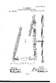
- FIG. 1 is a longitudinal sectional elevation of the trolly and press. view, partly of the press and partly of the trolly.
- Fig. 3 is a longitudinal section of box.
- Fig. 4 is a transverse section of box.
- Fig. 5 is a plan, showing general arrangement of works.
- A is a trolly or platform-car, of any ordinary kind, upon which is secured a frame, A, strongly fastened together, and containing any suitable number of boxes, B, (forty-eight being shown in the drawings,) these having their ends carried by transverse pieces A and being constructed as will now be described.
- Fig. 2 is a plan
- the pieces B, which form each box, are strongly dovetailed together, and, as shown in Figs. 3 and 4, are beveled off toward their lower edge, each box being divided into two or more compartments by pieces B beveled 011' in the same way as the sides and ends.
- a mold, C formed of wire mesh, and shaped, as shown, with rounded ends and bottom, secured in place by the flanges 0, attached by nails, or in any other suitable way, on the tops of the pieces B B.
- this track For operating this invention I prefer to arrange this track parallel to the canal G from which the peat is being dug, the excavator H lying alongside and delivering the pulped peat into the boxes through a port-hole underneath the spout or distributer I.
- the track D runs another, D, of exactly similar construction, and connecting with it by a turn-table, K, and from the end of this track D runs another of like construction, D, forming the hypothenuse of the triangle, turn-tables K K connecting its ends with the tracks D D.
- turn-tables may be of any suitable construction, such as a platform carrying a track suflicient for the wheelbase of the car, and turning on a central pin projecting up from a lower floor, it being essential, however, that these turn-tables should be capable of being transported without difficulty.
- drying-stages L having two or more floors, these being preferably of the construction for which Letters Patent of the United States No. 113,478 have already been granted to me.
- the press M may be of any suitable kind.
- screws N operated by means of beveled gears 0 0, (the latter of these being placed on a shaft rotated by handles or in any usual way,) operate to raise and lower a platform, P, a small collar, 19, holding in each case the end of the screw, and insuring its lifting the platform.
- the screws N work in horizontal pieces R, carried by a frame of any suitable kind, and are arranged to give the lift desired.
- the modus operandi of my invention is as follows: The cars, having the boxes B arranged as described in place upon them, are pushed along the track until each in succession comes under the distributing-spout of the excavator and is filled, the peat being leveled off by a scraper until it is slightly higher than the top of the boxes. The car thus filled is then run under the press, which is brought down upon it sufficiently to compress .the peat in the molds, the free water escaping through the wire mesh of which the molds are formed.
- the whole of this, together with the tramways D and D turntables, &c. may be removed and shifted farther up to the new working ground, parallel to the line of the cut to be made by the excavator, these being, as before mentioned, in long lengths, and all being easily transported, thus following and keeping pace with the working of the excavator.
Description
2 Sheets-Sheet 1.
D. AIKMAN.
MANUFACTURE OF PEAT FUEL. N 185,651 Patented Dec. 26, 1876.
\ k V -N Q THE GRAPHIC CD. NH
2 SheetsSheet 2. D. AIRMAN.
MANUFACTURE OF PEAT FUEL. No.185,657. Patented Dec. 26,1876.
THE GRAPHIC C(LNX UNITED STATES PATENT OFFICE DAVID AIKMAN, OF MONTREAL, QUEBEC, CANADA.
IMPROVEMENT IN THE MANUFACTURE OF PEAT FUEL.
Specification forming part of Letters Patent No. 185,65 7, dated December 26, 1876; application filed September 22, 1876.
the Manufacture of Peat Fuel; and I do hereby declare that the following is a full, clear,
and exact description of the same.
For many years past I have been engaged in the manufacture of peat fuel by the process patented by Mr. James Hodges, in which the appliances for excavating and pulping the peat are most excellent, but the process of drying it very deficient.
The manner in which the curing of the fuel is at present performed is as follows: The pulp is discharged from a long spout, called a distributer, over a prepared bed, about one hundred and twenty feet wide, where it is spread evenly over the ground, and lies there until it is sufficiently dry to allow of being marked out in the shape of bricks; it then lies somewhat longer, to allow it to get dry enough to be lifted from the ground and put onto racks or otherwise for drying. The time taken by this process is so long (especially where the season for working is short) that the fuel can seldom become thoroughly dry and fit for market, and there is great danger of its being attacked by frost before being removed from the beds, which would occasion a heavy loss. Beside this risk the expense of handling the fuel by this process is large.
To obviate these difficulties, avoid loss and expense, and cheapen the prod notion of the fuel to its lowest possible point is the object of my present invention, which is to be used in connection with the Hodges patent or other floating excavators.
In my arrangement the peat is received from one of the port-holes underneath the distributer into a series of molds arranged in a frame placed on a light platform-car or trolly, these molds being contained in boxes, (usually three in each,) of which there maybe from thirty to fifty in a set. The pulp which falls from the distributer is sufficiently fiuid'to allow it to fill up the molds. As soon as the set of boxes on one trolly is filled upit is moved backward from the direction in which the excavator advances and run under a screw-press,
(this being made the full superficial size of the trolly,) which, being brought down upon the pulp, forces it into shape in the molds, any free water that it may contain escaping through the wire gauze of which the mold is composed. While this is in progress another trolly has taken the place of the first under the distributer, and so on with the whole set of trollies, which may be about eight in number. The first is now released from the press and brought, by means of a light tramway and turn-table, to the face of the drying-racks; the boxes are quickly removed from their places in the frame, carried to the dryingracks, and upturned, leaving their contents, in the shape of soft rounded bricks, on the shelves, where they are allowed to remain usually from seven to fourteen days, according to the weather, when they are removed for storage or market.
By this arrangement of molds carried in trollies the Work is kept constantly going, and a large amount of manual labor is saved in the handling of the fuel, thus reducing the cost to a minimum, and, owing to the nature of the process, the fuel, when dry, is close and hard, giving a dense heat when burned.
To work this patent to advantage the size of the Hodges excavator used should be such as will cut a fifteeufoot canal, instead of a twenty-foot, as at present.
For fuller comprehension, however, of my invention, reference must be had to the annexed drawings, in which- Figure 1 is a longitudinal sectional elevation of the trolly and press. view, partly of the press and partly of the trolly. Fig. 3 is a longitudinal section of box. Fig. 4 is a transverse section of box. Fig. 5 is a plan, showing general arrangement of works.
Similar letters of reference indicate like parts.
A is a trolly or platform-car, of any ordinary kind, upon which is secured a frame, A, strongly fastened together, and containing any suitable number of boxes, B, (forty-eight being shown in the drawings,) these having their ends carried by transverse pieces A and being constructed as will now be described.
Fig. 2 is a plan The pieces B, which form each box, are strongly dovetailed together, and, as shown in Figs. 3 and 4, are beveled off toward their lower edge, each box being divided into two or more compartments by pieces B beveled 011' in the same way as the sides and ends. In each of these compartments is placed a mold, C, formed of wire mesh, and shaped, as shown, with rounded ends and bottom, secured in place by the flanges 0, attached by nails, or in any other suitable way, on the tops of the pieces B B. To cover these flanges, and still further hold them, are placed pieces B beveled outward, and secured on the top of the pieces B B The trolly A runs along light rails D, secured on longitudinals E, these in their turn being laid upon and attached to cross-ties F, the whole ofthis tramway being of light scantlings, in length of, say, about thirty feet, so that they can be easily lifted and carried when the track requires shifting.
For operating this invention I prefer to arrange this track parallel to the canal G from which the peat is being dug, the excavator H lying alongside and delivering the pulped peat into the boxes through a port-hole underneath the spout or distributer I. At right angles to the track D runs another, D, of exactly similar construction, and connecting with it by a turn-table, K, and from the end of this track D runs another of like construction, D, forming the hypothenuse of the triangle, turn-tables K K connecting its ends with the tracks D D. These turn-tables may be of any suitable construction, such as a platform carrying a track suflicient for the wheelbase of the car, and turning on a central pin projecting up from a lower floor, it being essential, however, that these turn-tables should be capable of being transported without difficulty. Alongside the track D, and at a little distance from it, are arranged drying-stages L, having two or more floors, these being preferably of the construction for which Letters Patent of the United States No. 113,478 have already been granted to me.
The press M, shown in Figs. 1 and 2, may be of any suitable kind. As shown in the drawings, screws N, operated by means of beveled gears 0 0, (the latter of these being placed on a shaft rotated by handles or in any usual way,) operate to raise and lower a platform, P, a small collar, 19, holding in each case the end of the screw, and insuring its lifting the platform. The screws N work in horizontal pieces R, carried by a frame of any suitable kind, and are arranged to give the lift desired. When the track is moved forward the press is moved with it to its proper place behind the spout or distributer.
The modus operandi of my invention is as follows: The cars, having the boxes B arranged as described in place upon them, are pushed along the track until each in succession comes under the distributing-spout of the excavator and is filled, the peat being leveled off by a scraper until it is slightly higher than the top of the boxes. The car thus filled is then run under the press, which is brought down upon it sufficiently to compress .the peat in the molds, the free water escaping through the wire mesh of which the molds are formed. ()n reaching the end of the track D the car is turned and run onto the track D, away from the cut; the boxes B are then removed from the car, (the key-box, or that part in last, being first taken out, thus allowing all the rest to be easily lifted 0d,) whence they are taken to the stages L, and there upturned, the bricks of peat contained in the molds being thus turned out upon the shelves, the beveling away of the top pieces B and the peculiar shape of the molds obviating any chance of the material sticking in them, or failing to be at once dislodged. The boxes thus emptied are then put back on the car, which passes to the end of the track D, and is run along the track D to the tram D, to be again filled. By this means the operation is continuous, as while one car is discharging its contents a second will be under the press, a third in process of filling, and others being run along to be filled.
Before the boxescontained in the trollies are again brought under the distributer to be filled, I prefer to direct upon them a stream of water from a force-pump, worked by the engine of the excavator, so as to clean from them any particles of peat which may adhere thereto.
As soon as the excavator has worked the length of the track D, the whole of this, together with the tramways D and D turntables, &c., may be removed and shifted farther up to the new working ground, parallel to the line of the cut to be made by the excavator, these being, as before mentioned, in long lengths, and all being easily transported, thus following and keeping pace with the working of the excavator.
Having thus described the nature of my invention, what I claim is as follows:
1. The combination, with an apparatus for excavating, grinding, and pulping peat, of wire molds, carried on cars to receive said peat, a screw-press to force out the excess of water contained therein, and stages for drying the same, all substantially as herein set forth 2. The boxes B, divided into two or more compartments, and containing molds of wiremesh for the reception of pulped peat, constructed and arranged substantially as shown and described.
3. In combination with the boxes B, carried in any suitable car, the screw or other press M, operating as and for the purposes set forth.
Montreal, 18th day of September, A. D. 1876.
DAVID AIKMAN.
Witnesses:
FBAS. HY. REYNOLDS, HARLEY LAWRIE.
Publications (1)
| Publication Number | Publication Date |
|---|---|
| US185657A true US185657A (en) | 1876-12-26 |
Family
ID=2255063
Family Applications (1)
| Application Number | Title | Priority Date | Filing Date |
|---|---|---|---|
| US185657D Expired - Lifetime US185657A (en) | Improvement in the manufacture of peat fuel |
Country Status (1)
| Country | Link |
|---|---|
| US (1) | US185657A (en) |
-
0
- US US185657D patent/US185657A/en not_active Expired - Lifetime
Similar Documents
| Publication | Publication Date | Title |
|---|---|---|
| US5566619A (en) | Method and apparatus for rehabilitating the subgrade supporting a ballast bed | |
| US185657A (en) | Improvement in the manufacture of peat fuel | |
| US1716125A (en) | Method of lining tunnels with concrete and apparatus therefor | |
| US2251990A (en) | Material unloading system | |
| US1258299A (en) | Apparatus for laying street and road paving material. | |
| US1675607A (en) | Self-dumping barge | |
| US785252A (en) | Apparatus for raising superstructures and ballasting railway road-beds. | |
| US1856589A (en) | Concrete flume structure and method of building same | |
| US2207303A (en) | Portable mixing plant | |
| US1329554A (en) | Ballast treating | |
| US1007912A (en) | Starch-shovel. | |
| US1300800A (en) | System for storing bulky materials. | |
| US122498A (en) | Improvement in the manufacture of concrete pavements and in machinery forthe same | |
| US1302533A (en) | Freight-car. | |
| US1707923A (en) | Drop pit | |
| US71553A (en) | Improvement in apparatus for constructing railroads | |
| US719518A (en) | Storage and reloading apparatus. | |
| US1013229A (en) | Dumping-trestle. | |
| US1368456A (en) | Coal-handling device | |
| US2587681A (en) | Log handling apparatus | |
| US399634A (en) | Coke-oven | |
| US1084889A (en) | Unloading sand-scow. | |
| US659008A (en) | Machine for excavating, conveying, and loading ballast upon railways-cars. | |
| US1165971A (en) | Storage-bin. | |
| CN206814730U (en) | A kind of white spirit brewing solid state fermentation Cellar opening device |