US1856563A - Annealing furnace - Google Patents
Annealing furnace Download PDFInfo
- Publication number
- US1856563A US1856563A US447329A US44732930A US1856563A US 1856563 A US1856563 A US 1856563A US 447329 A US447329 A US 447329A US 44732930 A US44732930 A US 44732930A US 1856563 A US1856563 A US 1856563A
- Authority
- US
- United States
- Prior art keywords
- annealing
- furnace
- steam
- chamber
- relief valve
- Prior art date
- Legal status (The legal status is an assumption and is not a legal conclusion. Google has not performed a legal analysis and makes no representation as to the accuracy of the status listed.)
- Expired - Lifetime
Links
- 238000000137 annealing Methods 0.000 title description 24
- 229910052751 metal Inorganic materials 0.000 description 15
- 239000002184 metal Substances 0.000 description 15
- 238000010438 heat treatment Methods 0.000 description 10
- XLYOFNOQVPJJNP-UHFFFAOYSA-N water Substances O XLYOFNOQVPJJNP-UHFFFAOYSA-N 0.000 description 9
- 238000010791 quenching Methods 0.000 description 7
- 230000000171 quenching effect Effects 0.000 description 7
- 238000001816 cooling Methods 0.000 description 6
- 238000007789 sealing Methods 0.000 description 6
- 230000001590 oxidative effect Effects 0.000 description 4
- 238000010276 construction Methods 0.000 description 2
- 229910045601 alloy Inorganic materials 0.000 description 1
- 239000000956 alloy Substances 0.000 description 1
- 230000015572 biosynthetic process Effects 0.000 description 1
- 239000011449 brick Substances 0.000 description 1
- 238000005485 electric heating Methods 0.000 description 1
- -1 ferrous metals Chemical class 0.000 description 1
- 238000004519 manufacturing process Methods 0.000 description 1
- 238000012986 modification Methods 0.000 description 1
- 230000004048 modification Effects 0.000 description 1
- 229910001120 nichrome Inorganic materials 0.000 description 1
- 239000011819 refractory material Substances 0.000 description 1
- 238000005476 soldering Methods 0.000 description 1
Images
Classifications
-
- C—CHEMISTRY; METALLURGY
- C21—METALLURGY OF IRON
- C21D—MODIFYING THE PHYSICAL STRUCTURE OF FERROUS METALS; GENERAL DEVICES FOR HEAT TREATMENT OF FERROUS OR NON-FERROUS METALS OR ALLOYS; MAKING METAL MALLEABLE, e.g. BY DECARBURISATION OR TEMPERING
- C21D9/00—Heat treatment, e.g. annealing, hardening, quenching or tempering, adapted for particular articles; Furnaces therefor
Definitions
- This invention relates to non-oxidizing annealing furnaces, and more particularly to a furnace for bright annealing non-ferrous metals in the absence of air.
- One object of this invention is to provide an annealing furnace of the above nature having an inverted annealing chamber provided with an'open bottom below which is a sealing tank containing water in which the hot metal is quenched after annealing.
- a further object is to provide an annealing furnace of the above nature having an exhaust steam outlet at the bottom of the annealing chamber just above the water sealing tank for carrying off the steam generated by the quenching without cooling the annealing chamber.
- a further object of this invention is to provide an annealing furnace of the above nature which will be relatively simple in construction, inexpensive to manufacture and operate, clean and cool in operation, easy to install and manipulate, compact, and very efiicient and durable in use.
- Fig. 1 represents a fragmentary vertical sectional view taken through the apparatus.
- Fig. 2 is a side View of the upper portion of the steam exhaust pipe showing the automatic relief valve and the collector for condensed steam.
- the numeral 10 indicates an inverted annealing chamber of any suitable refractory material having the usual inner lining of fire brick 11.
- Heat is supplied to the annealing chamber 10 by a plurality of electric heating elements 12 herein disclosed as vertically spaced insulating ribbons of nichrome alloy, said ribbons being preferably wound in a sinuous manner to furnish a uniform supply of heat.
- Stem or other suitable non-oxidizing gas is continuously supplied to the heating chamber through a plurality of horizontal pipes 13 passing through the side walls of the furnace at a point just below the upper arch 14.
- the metal to be annealed is supported while in the anealing chamber 10 by means of a platform 15 having a plurality of supporting rods 16 extending upwardly therefrom and adapted to encircle the charge, not shown.
- the platform 15 is adapted to be raised into the annealing chamber and lowered therefrom into the water or sealing tank 17 by means of a hydraulic ram, not shown.
- this invention is not limited to electrically-heated furnaces, but-is equally applicable to furnaces heated by oil, gas, etc., including the so-called retort type of annealing furnace.
- a small opening 24 in the stack 18 at the bottom of the catch 23 permits the condensed steam to flow down into the stack. By means of this construction, moisture will be prevented. from flowing down on the outside of the furnace and injuring the appearance thereof.
- an annealing apparatus an inverted heating chamber closed at the top and open at the bottom, a sealing tank below said chamber containing water for quenching the hot metal after annealing, and an exhaust stack opening into the bottom of said heat ing chamber for conducting away the steam generated by said quenching without loss of efiiciency by the cooling of said heating chamber, said stack having an automatic relief valve including a freely swinging vane adapted to be opened outwardly by the pressure of the escaping steam and'to swing inwardly to prevent formation of vacuum in said apparatus.
- an inverted valve In an annealing apparatus, an inverted valve, a curved trough below said relief valve for collecting condensed moisturefrom said valve, and means to conduct said moisture back into said stack.
- an annealing apparatus In an annealing apparatus, an inverted heating chamber closed at the top and open at the bottom, a sealing tank below said chamber containing water for quenching'the hot metal after annealing, an exhaust stack opening into the bottom of said heating chamber for conducting away the steam gen erated by said quenching without loss of efficiency by the cooling of said heating chamber, said stack having an automatic relief valve, and an upwardly inclined curved trough below said relief valve for collecting condensed moisture from said valve.
Landscapes
- Chemical & Material Sciences (AREA)
- Engineering & Computer Science (AREA)
- Physics & Mathematics (AREA)
- Thermal Sciences (AREA)
- Crystallography & Structural Chemistry (AREA)
- Mechanical Engineering (AREA)
- Materials Engineering (AREA)
- Metallurgy (AREA)
- Organic Chemistry (AREA)
- Heat Treatment Of Strip Materials And Filament Materials (AREA)
Description
May 3, 1932. H. A. KENWORTHY ANNEALING FURNACE Filed April 25, 1930 MT NEY Patented May 3, 1932 o STATES PATENT OFFICE ANNEALING FURNACE Application filed April 25, 1930. Serial No. 447,329.
This invention relates to non-oxidizing annealing furnaces, and more particularly to a furnace for bright annealing non-ferrous metals in the absence of air.
One object of this invention is to provide an annealing furnace of the above nature having an inverted annealing chamber provided with an'open bottom below which is a sealing tank containing water in which the hot metal is quenched after annealing.
A further object is to provide an annealing furnace of the above nature having an exhaust steam outlet at the bottom of the annealing chamber just above the water sealing tank for carrying off the steam generated by the quenching without cooling the annealing chamber.
A further object of this invention is to provide an annealing furnace of the above nature which will be relatively simple in construction, inexpensive to manufacture and operate, clean and cool in operation, easy to install and manipulate, compact, and very efiicient and durable in use.
WVith these and other objects in view, there has been illustrated on the accompanying drawings, one form in which the invention may be conveniently embodied in practice.
In the drawings:
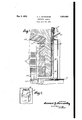
Fig. 1 represents a fragmentary vertical sectional view taken through the apparatus.
Fig. 2 is a side View of the upper portion of the steam exhaust pipe showing the automatic relief valve and the collector for condensed steam.
In previous forms of non-oxidizing annealing furnaces where the hot metal was quenched in the sealing tank of water located below the heating chamber, it was customary to conduct the steam, resulting from the quenching, upwardly through the heating chamber, where it was exhausted through an automatic relief valve located at the top of the furnace. The passage of the steam through the heating furnace caused a considerable cooling off of the interior thereof resulting in needless loss of heat and low efficiency.
By means of the present invention, the
above and other disadvantages have been avoided. This has been accomplished by con structing a furnace so that the steam resulting from the quenching of the heated metal will be conducted out from the bottom of the furnace at a point just above the water line and exhausted through a sheet metal stack having a relief valve at the top thereof. By thus eliminating the cooling off of the inside of the furnace, it has been found from the use of this invention that fully 35 percent more metal per unit of heat supplied can be annealed.
Referring now to the drawings in which like reference numerals denote corresponding parts throughout the several views, the numeral 10 indicates an inverted annealing chamber of any suitable refractory material having the usual inner lining of fire brick 11. Heat is supplied to the annealing chamber 10 by a plurality of electric heating elements 12 herein disclosed as vertically spaced insulating ribbons of nichrome alloy, said ribbons being preferably wound in a sinuous manner to furnish a uniform supply of heat. Stem or other suitable non-oxidizing gas is continuously supplied to the heating chamber through a plurality of horizontal pipes 13 passing through the side walls of the furnace at a point just below the upper arch 14.
The metal to be annealed is supported while in the anealing chamber 10 by means of a platform 15 having a plurality of supporting rods 16 extending upwardly therefrom and adapted to encircle the charge, not shown. The platform 15 is adapted to be raised into the annealing chamber and lowered therefrom into the water or sealing tank 17 by means of a hydraulic ram, not shown.
Then a heated metal charge is lowered from the furnace into the water seal 17, a considerable amount of steam is generated. To exhaust this steam wit iout cooling off the annealing chamber, provision is made of one or more L shaped stacks or ducts l8 preferably constructed of sheet metal and being rectangular in cross-section, the lower horizontal leg of said duct 18 being positioned just above the water level of the seal 17. The upper part of the vertical leg of the duct 18 is provided with an automatic relief valve 2 Q I V 19, said'valve comprising a freely swinging circular vertical vane 20 hinged on a rod 21 and losely fitting within a circular surrounding collar 22. By means of this construc- 5 tion it will be seen that the large Volume of steam generated from the quenchingof the hot metal will passupwardly through the duct 18 and escape past the vane 20 into the outer atmosphere.
It will of course be understood that under normal conditions, as while the metal is being heated, the vane 20 will remain suspended in the vertical position shown, since the slow stream of steam or other non-oxidizing gas which flows into the annealing chamber from the pipes-13 will pass out through the loose vane 20 of the relief valve 19 without raising the vane 20.
It will be understood that this invention is not limited to electrically-heated furnaces, but-is equally applicable to furnaces heated by oil, gas, etc., including the so-called retort type of annealing furnace.
I In order to collect any moisture which may condense immediately outside the relief valve 19, provision is made of a curved sheet metal drip catch 23 attached as by soldering to the metal duct 18 below said relief valve.
A small opening 24 in the stack 18 at the bottom of the catch 23 permits the condensed steam to flow down into the stack. By means of this construction, moisture will be prevented. from flowing down on the outside of the furnace and injuring the appearance thereof.
While there has been disclosed in this specification one form in which the invention may be embodied, it is to be understood that this form is shown for the purpose of illustration only, andthat the invention is not to be limited to the specific disclosure but may be modified and embodied in various other forms without departing from its spirit. In short, the invention includes all the modifications and embodiments coming within the scope of the following claims.
Having thus fully described the invention, what is claimed as new, and for which it is desired to secure Letters Patent, is:
'o 1. In an annealing apparatus, an inverted heating chamber closed at the top and open at the bottom, a sealing tank below said chamber containing water for quenching the hot metal after annealing, and an exhaust stack opening into the bottom of said heat ing chamber for conducting away the steam generated by said quenching without loss of efiiciency by the cooling of said heating chamber, said stack having an automatic relief valve including a freely swinging vane adapted to be opened outwardly by the pressure of the escaping steam and'to swing inwardly to prevent formation of vacuum in said apparatus. I
C3 2. In an annealing apparatus, an inverted valve, a curved trough below said relief valve for collecting condensed moisturefrom said valve, and means to conduct said moisture back into said stack.
3. In an annealing apparatus, an inverted heating chamber closed at the top and open at the bottom, a sealing tank below said chamber containing water for quenching'the hot metal after annealing, an exhaust stack opening into the bottom of said heating chamber for conducting away the steam gen erated by said quenching without loss of efficiency by the cooling of said heating chamber, said stack having an automatic relief valve, and an upwardly inclined curved trough below said relief valve for collecting condensed moisture from said valve.
In testimony whereof, I have affixed no signature to this specification.
HOWARD A. KENVJORTHY.
Priority Applications (1)
| Application Number | Priority Date | Filing Date | Title |
|---|---|---|---|
| US447329A US1856563A (en) | 1930-04-25 | 1930-04-25 | Annealing furnace |
Applications Claiming Priority (1)
| Application Number | Priority Date | Filing Date | Title |
|---|---|---|---|
| US447329A US1856563A (en) | 1930-04-25 | 1930-04-25 | Annealing furnace |
Publications (1)
| Publication Number | Publication Date |
|---|---|
| US1856563A true US1856563A (en) | 1932-05-03 |
Family
ID=23775927
Family Applications (1)
| Application Number | Title | Priority Date | Filing Date |
|---|---|---|---|
| US447329A Expired - Lifetime US1856563A (en) | 1930-04-25 | 1930-04-25 | Annealing furnace |
Country Status (1)
| Country | Link |
|---|---|
| US (1) | US1856563A (en) |
-
1930
- 1930-04-25 US US447329A patent/US1856563A/en not_active Expired - Lifetime
Similar Documents
| Publication | Publication Date | Title |
|---|---|---|
| US1856563A (en) | Annealing furnace | |
| US2252046A (en) | Furnace | |
| US1952402A (en) | Annealing furnace | |
| CN216482225U (en) | Novel crucible type smelting heat preservation furnace hearth structure | |
| CN211451821U (en) | Non-ferrous metal melting furnace | |
| US1925028A (en) | Heat treating apparatus | |
| GB332656A (en) | Process of and apparatus for bright annealing metals | |
| RU7180U1 (en) | FURNACE FOR A BATH | |
| GB544112A (en) | Improvements in the method of melting copper | |
| SU46684A1 (en) | Metal Portable Furnace | |
| US1694376A (en) | Furnace for reduction of iron | |
| GB192458A (en) | Improvements in or relating to heaters for bitumen or other material | |
| CN204404254U (en) | Honeycomb briquette stove | |
| US380732A (en) | smith | |
| US1720365A (en) | Heater | |
| CN208983847U (en) | The inlet seal cabin anti-condensation device of Industrial Stoves | |
| US1736963A (en) | Combined incinerator and fuel economizer | |
| US1626054A (en) | Heating furnace or stove | |
| SU5620A1 (en) | Device for heating samovars filled with hot water from the boiler | |
| US972703A (en) | Crucible-furnace. | |
| CN206794744U (en) | A kind of baking and thermal insulation device of iron bag or ladle | |
| US803337A (en) | Metallurgical furnace. | |
| US1293074A (en) | Furnace. | |
| US795218A (en) | Furnace for treating sheet iron and steel. | |
| CN205561538U (en) | Continuous tapping device |