US1856545A - Tag holder - Google Patents
Tag holder Download PDFInfo
- Publication number
- US1856545A US1856545A US445438A US44543830A US1856545A US 1856545 A US1856545 A US 1856545A US 445438 A US445438 A US 445438A US 44543830 A US44543830 A US 44543830A US 1856545 A US1856545 A US 1856545A
- Authority
- US
- United States
- Prior art keywords
- card
- holder
- frame
- tag holder
- tongue
- Prior art date
- Legal status (The legal status is an assumption and is not a legal conclusion. Google has not performed a legal analysis and makes no representation as to the accuracy of the status listed.)
- Expired - Lifetime
Links
- 239000000463 material Substances 0.000 description 5
- 238000005452 bending Methods 0.000 description 2
- 238000010276 construction Methods 0.000 description 2
- 239000002184 metal Substances 0.000 description 2
- 230000003014 reinforcing effect Effects 0.000 description 2
- 230000000994 depressogenic effect Effects 0.000 description 1
- MOYKHGMNXAOIAT-JGWLITMVSA-N isosorbide dinitrate Chemical compound [O-][N+](=O)O[C@H]1CO[C@@H]2[C@H](O[N+](=O)[O-])CO[C@@H]21 MOYKHGMNXAOIAT-JGWLITMVSA-N 0.000 description 1
Images
Classifications
-
- G—PHYSICS
- G09—EDUCATION; CRYPTOGRAPHY; DISPLAY; ADVERTISING; SEALS
- G09F—DISPLAYING; ADVERTISING; SIGNS; LABELS OR NAME-PLATES; SEALS
- G09F3/00—Labels, tag tickets, or similar identification or indication means; Seals; Postage or like stamps
- G09F3/08—Fastening or securing by means not forming part of the material of the label itself
- G09F3/18—Casings, frames or enclosures for labels
- G09F3/20—Casings, frames or enclosures for labels for adjustable, removable, or interchangeable labels
- G09F3/202—Casings, frames or enclosures for labels for adjustable, removable, or interchangeable labels for labels being formed by a combination of interchangeable elements, e.g. price labels
Definitions
- My invention relates to kimprovements in tag holders', and vit consists' ⁇ in the combinations, constructions and arrangements hereinafter described and claimed.
- An object of myrinvention is to provide a tag holder which is constructed from a single piece of material and which is designed to removably hold various combinations of cards.
- the device is extremely simple in construci-c tion and is durable and efficient for the purpose intended.
- V Y 4 The card holder is provided with novel means for securing cards tothe holder, these cards being removable at the will ofthe operator.
- a supporting member is used for the vholder and is integral therewith, and this Vmember is provided with a bracing member .th'atkeeps'the supporting 'member the desired distance away from the main part of the -Qo holder.
- the bracing membery also acts as a support for the holder whenjthe device is placed on top of a'bottle. It should further be noted that the openingv provided Vby the bending of thebracing member receives a l25 Mportion of the bottle top.
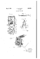
- Figure 1 is a plan view of the card holder prior to the bending of the parts into operative position
- Figure 3 is a section along the line 3*-3 of Figure 2, and
- Figure4 is a perspective view of the com- .4'0 plete holder showing vcards in position.
- window 1 being preferably larger in size than the other window,although both may be varied in size without departing from the spirit and scope ofthe invention.
- the part A is provided with a raised portion 3 that encircles both windows and with a Vraised portion 4 that extends between the windows.
- the portions 3 and 4 act as reinforcing means for the part A.
- the windows 1 and 2 are provided with central reenforcing 4strips 5 and 6 that are integral with the metal forming the portion A.
- the front surfaces ofr these strips are depressed aslight distance for receiving cards "i and 8 (see Figure 4).
- Figure 2 shows a cross sectional view through the strips 5 and .6, and it will be noted that the strip 5 has a tongue 9 struck therefrom and that the strip 6 hasa slot 10 formed adjacent Vto the 'top of the'strip.
- part A are provided with inwardly-extending flanges 11 (see Figure l2,) for reenforcing purposes.
- the part A is integral with part B as shown ⁇ in Figure 1, and both are folded with re- 7 0 spect to y.each other along adotted line 12.
- a slot 13. is provided .at the juncture of the pieces A and B.
- the piece or rest B may have its sides 14 shaped in any novel manner in order to add ,75 to the design and appearance of the device.
- the 'parts A Vand are inclined with respect vto each other as shown in Fi re 2 and are held at lthe desired distance y the krbracingfpart*C. It will be noted in Figure ⁇ lpthat the partfC is cut from' the vpart .B20
- the part C forms the Sheet of metal in the lmanner shown along a line 19.
- the part C consists of a large tongue-shaped member 20 having an integral small tongue-shaped member 21.
- the large tongue 20 is bent along a dotted line 22 in Figure l, and the small tongue is bent along a dotted line 23.
- the small tongue is then inserted underneath the tongue 9, and the portion of the tongue 21 that extends below the tongue 9 is bent back upon itself as shown at 24 in Figure 2. It will thus be seen that the tongue 20 is disposed in a horizontal position in Figure 2.
- the device will take the appear-ance as ⁇ shown in Figure 2 when the parts are bent? and secured to each other in the manner already described.
- the entire device V may be made in three operations.
- the iirst operaftion cuts the holes 25 Aand 26 forthe cards rand also forms the reinforcing ribs or por-
- the third operation forms the slot 13, and thedevi'ce may then be folded by hand or machine into the structure shown in Figures 2 and 4.
- FIG. 3 shows how thek cards 7 land 8 may be disposed in place.
- This ligure shows the strip 5 and the lianges l1 as reacting. as vretaining means for the card 8.
- the card is entered from the back and one side of the'partA and is slid across the front surface ofthe strip 5 until the card is in place.
- the tendencyof the card to remainin a flat plane will cause the edges to be received in the flanges-11, and the flanges together 7,40 V,with the strip fwill prevent the card from falling out until the cardv-is manually reimoved.
- the card .7 is disposed in place.
- Thecards may have diiferentinfory 5 mation printed thereon, and the cardsmay be changed as often as desired to ⁇ present diiferentvinformation. .It Vshould also'be clearly understood that'the cards may be printed on both l sides and either-side dis'- posed to the front so asto change theinformation given. f
- a third card 27 shown in Figure t may Vbe placed in the tag holder,v and the corner fof this card is preferably inserted in the i. .A slot 13 .and is received in the sloty 10. These two slots cooperate to clamp the card and 'hold it in the position shown. Itis obvious iplaced upon a bottle indicated generallyatv 'at the will of the operator.
- FIG. 2 I show the deviceras being T28.v
- the bracing ⁇ portion -20 rests uponthe vtopk of A the',bottle, and a AportionV of.4 the top 'ofthe bottlejpassedv through an .opening 29 provided by the removed tongue 20; Edges ⁇ ⁇ ceived in the slot'.
- Openings 31 in the part 16 vare provided for receiving nails or other suitable fastening means if it is desired to permanently secure the tag holder to the supporting surface. This is not necessary, because the holder is self-supporting and may be placed on variousl articles'.
- the device' is extremely simple in construction and has many/features which make it attractive. It should be noted ⁇ that the strips Aorloack members 5 and 6 are set off from the frame by the thickness of the card.
- a tag holder comprising asingle piece Vof material having a frame portion, a rest for supporting the frame in an inclined position,
- a frame having a card .receivingwindow, a card'retaining strip associated with Vthe vwindow, and having a slot therein,'said frame having aslot positioned vnear the first slot, the edges of bothslotsbe- -ing designedto'grlp a card at'two different places.
- a tag holder comprising a frame portion, a rest for" supporting the frame, and a bracing member extending between the rest and the frame and adapted to be supported fon an object, said resthaving an opening formed therein below the bracing member for receiving a portion ofthe article.
- VA tag holderv comprising a lframevportion, a rest for supportingthe frame, and a bracing member extending between the rest Vand the frame and adapted torbe supported on an object, said vrest Vhaving an 'openingformed therein belowithe bracing member and :allowing a portion ofthe article tov project therethrough. jfor. ,preventingf lateral movement of the tag holder.
- v 6; ⁇ ,A.tagfholder fashioned froniasingleV piece of material 'and' being bent intermediate of its ends so as to present a card displaying frame and a rest arranged at an angle with respect to each other, and a bracing member struck from the rest and projecting into engagement with the frame and being adapted to be supported by an article, the opening provided in the rest by the struck out member being arranged below the bracing member and allowing a portion of the article to project therethrough.
Landscapes
- Physics & Mathematics (AREA)
- General Physics & Mathematics (AREA)
- Engineering & Computer Science (AREA)
- Theoretical Computer Science (AREA)
- Credit Cards Or The Like (AREA)
Description
May 31.1932. D. GARFINKLE 1,856,545
TAQHOLDER iled April .18, 1950 A TTORNEYS.
`Patented May 3, 1932 vrPA'll'rl'ltlT OFFICE DAVID. GAR-FINKLE, l017'? ALAMEDA, CALIFORNIA TAG HOLDER Applisefien medpril 18.
My invention relates to kimprovements in tag holders', and vit consists' `in the combinations, constructions and arrangements hereinafter described and claimed.
,5 An object of myrinvention is to provide a tag holder which is constructed from a single piece of material and which is designed to removably hold various combinations of cards. The device is extremely simple in construci-c tion and is durable and efficient for the purpose intended. V Y 4 The card holder is provided with novel means for securing cards tothe holder, these cards being removable at the will ofthe operator. A supporting member is used for the vholder and is integral therewith, and this Vmember is provided with a bracing member .th'atkeeps'the supporting 'member the desired distance away from the main part of the -Qo holder. The bracing memberyalso acts as a support for the holder whenjthe device is placed on top of a'bottle. It should further be noted that the openingv provided Vby the bending of thebracing member receives a l25 Mportion of the bottle top.
` Other objects and advantages will appear as the specification proceeds, and the'novel features of the invention will be particularly pointed out inthe claims hereto annexed.
30 My invention is illustrated in the accompanying -drawings,in which Figure 1 is a plan view of the card holder prior to the bending of the parts into operative position,
device,
Figure 3 is a section along the line 3*-3 ofFigure 2, and
Figure4 is a perspective view of the com- .4'0 plete holder showing vcards in position.
,4.5 A is provided with two windows l1 and 2, the
Figure 2is a vertical section through the 1930. serial No. 445,4381
window 1 being preferably larger in size than the other window,although both may be varied in size without departing from the spirit and scope ofthe invention. The part A is provided with a raised portion 3 that encircles both windows and with a Vraised portion 4 that extends between the windows.
The portions 3 and 4 act as reinforcing means for the part A.
The windows 1 and 2 are provided with central reenforcing 4strips 5 and 6 that are integral with the metal forming the portion A. The front surfaces ofr these strips are depressed aslight distance for receiving cards "i and 8 (seeFigure 4). Figure 2 shows a cross sectional view through the strips 5 and .6, and it will be noted that the strip 5 has a tongue 9 struck therefrom and that the strip 6 hasa slot 10 formed adjacent Vto the 'top of the'strip. The three edges of the ,e5
part A are provided with inwardly-extending flanges 11 (see Figure l2,) for reenforcing purposes.
The part A is integral with part B as shown `in Figure 1, and both are folded with re- 7 0 spect to y.each other along adotted line 12. A slot 13.is provided .at the juncture of the pieces A and B.
The piece or rest B may have its sides 14 shaped in any novel manner in order to add ,75 to the design and appearance of the device.
'1t willl also be noted from Figure 1 that a design is workedout .by raised portions 15 that also actas reenforcing means for the part B. The lower portionl of the part Uv80 B is foldable along a dotted line 17 andy extends in the manner shown in Figure 2 when thus folded. `The part B is reenforced along its marginal edges byl flanges 18 (see Figure 2). v@5
The 'parts A Vand are inclined with respect vto each other as shown in Fi re 2 and are held at lthe desired distance y the krbracingfpart*C. It will be noted in Figure `lpthat the partfC is cut from' the vpart .B20
forms the Sheet of metal in the lmanner shown along a line 19. The part C consists of a large tongue-shaped member 20 having an integral small tongue-shaped member 21. The large tongue 20 is bent along a dotted line 22 in Figure l, and the small tongue is bent along a dotted line 23. The small tongue is then inserted underneath the tongue 9, and the portion of the tongue 21 that extends below the tongue 9 is bent back upon itself as shown at 24 in Figure 2. It will thus be seen that the tongue 20 is disposed in a horizontal position in Figure 2.
Fromthel foregoing description of lthe various parts of the device, the operation thereof'may be readily understood'. if*
The device will take the appear-ance as` shown in Figure 2 when the parts are bent? and secured to each other in the manner already described. The entire device Vmay be made in three operations. The iirst operaftion cuts the holes 25 Aand 26 forthe cards rand also forms the reinforcing ribs or por- The second voperation in Figure 1. The third operation forms the slot 13, and thedevi'ce may then be folded by hand or machine into the structure shown inFigures 2 and 4.
--Reference to Figure 3 shows how thek cards 7 land 8 may be disposed in place. This ligure shows the strip 5 and the lianges l1 as reacting. as vretaining means for the card 8.
The cardis entered from the back and one side of the'partA and is slid across the front surface ofthe strip 5 until the card is in place. The tendencyof the card to remainin a flat plane will cause the edges to be received in the flanges-11, and the flanges together 7,40 V,with the strip fwill prevent the card from falling out until the cardv-is manually reimoved.
' vIn like mannerthe card .7 is disposed in place.` Thecards may have diiferentinfory 5 mation printed thereon, and the cardsmay be changed as often as desired to` present diiferentvinformation. .It Vshould also'be clearly understood that'the cards may be printed on both l sides and either-side dis'- posed to the front so asto change theinformation given. f
A third card 27 shown in Figure t may Vbe placed in the tag holder,v and the corner fof this card is preferably inserted in the i. .A slot 13 .and is received in the sloty 10. These two slots cooperate to clamp the card and 'hold it in the position shown. Itis obvious iplaced upon a bottle indicated generallyatv 'at the will of the operator.
thatthis card may have different data printed j In Figurey 2 I show the deviceras being T28.v The bracing` portion -20 rests uponthe vtopk of A the',bottle, and a AportionV of.4 the top 'ofthe bottlejpassedv through an .opening 29 provided by the removed tongue 20; Edges` `ceived in the slot'.
30 of the line of cutting 19 contact with the neck of the bottle and tend to hold the tag holder in position. This is not absolutely essential because the weight of the holder will cause it to rest upon the top ofthe bottle in the manner shown. Openings 31 in the part 16 (see Figure 1) vare provided for receiving nails or other suitable fastening means if it is desired to permanently secure the tag holder to the supporting surface. This is not necessary, because the holder is self-supporting and may be placed on variousl articles'.
The device'is extremely simple in construction and has many/features which make it attractive. It should be noted` that the strips Aorloack members 5 and 6 are set off from the frame by the thickness of the card.
- Although I havev shown and described one embodiment of my invention, it is to be understood that the same is susceptible of various changes, vand I reserve the vright to employ such changes as may come within the scope of the invention as claimed."
:.lclaim:
y1. A tag holder comprising asingle piece Vof material having a frame portion, a rest for supporting the frame in an inclined position,
a bend in the material,y said material having la slot in the bend for receiving a card, and
means for holding the cornerofthe card re- 3. In a tagholder, a frame ,having a card .receivingwindow, a card'retaining strip associated with Vthe vwindow, and having a slot therein,'said frame having aslot positioned vnear the first slot, the edges of bothslotsbe- -ing designedto'grlp a card at'two different places. Y p
4. A tag holder comprising a frame portion, a rest for" supporting the frame, anda bracing member extending between the rest and the frame and adapted to be supported fon an object, said resthaving an opening formed therein below the bracing member for receiving a portion ofthe article.
5. VA tag holderv comprising a lframevportion, a rest for supportingthe frame, and a bracing member extending between the rest Vand the frame and adapted torbe supported on an object, said vrest Vhaving an 'openingformed therein belowithe bracing member and :allowing a portion ofthe article tov project therethrough. jfor. ,preventingf lateral movement of the tag holder.
. DAVID GARFINKLE.
Priority Applications (1)
| Application Number | Priority Date | Filing Date | Title |
|---|---|---|---|
| US445438A US1856545A (en) | 1930-04-18 | 1930-04-18 | Tag holder |
Applications Claiming Priority (1)
| Application Number | Priority Date | Filing Date | Title |
|---|---|---|---|
| US445438A US1856545A (en) | 1930-04-18 | 1930-04-18 | Tag holder |
Publications (1)
| Publication Number | Publication Date |
|---|---|
| US1856545A true US1856545A (en) | 1932-05-03 |
Family
ID=23768902
Family Applications (1)
| Application Number | Title | Priority Date | Filing Date |
|---|---|---|---|
| US445438A Expired - Lifetime US1856545A (en) | 1930-04-18 | 1930-04-18 | Tag holder |
Country Status (1)
| Country | Link |
|---|---|
| US (1) | US1856545A (en) |
-
1930
- 1930-04-18 US US445438A patent/US1856545A/en not_active Expired - Lifetime
Similar Documents
| Publication | Publication Date | Title |
|---|---|---|
| US1681586A (en) | Display-card holder | |
| US2504277A (en) | Three-in-one greeting card | |
| US2538908A (en) | Shelf divider | |
| US3516585A (en) | Tool mount | |
| US2054098A (en) | Lap table | |
| US2801036A (en) | Garment hangers | |
| US2886182A (en) | Counter rack | |
| US3082557A (en) | Advertising display board | |
| US3334920A (en) | Easel type ring binder | |
| US2591170A (en) | Collapsible display device | |
| US3501072A (en) | Collapsible support | |
| US2880534A (en) | Display easel | |
| US2658773A (en) | Golf score cardholder | |
| US2550857A (en) | Standard for displaying price cards and the like | |
| US1856545A (en) | Tag holder | |
| US1778728A (en) | Swinging frame | |
| US2640288A (en) | Price tag holder | |
| US2218409A (en) | smalls | |
| US1944070A (en) | Crown molding | |
| US2340421A (en) | Display card holder | |
| US2020780A (en) | Price tag support | |
| US1765971A (en) | Folding case for timepieces | |
| US2042813A (en) | Sign holder for cans | |
| US2075401A (en) | Display stand | |
| US2259772A (en) | Display card |