US1856542A - Rotary steam engine - Google Patents
Rotary steam engine Download PDFInfo
- Publication number
- US1856542A US1856542A US313743A US31374328A US1856542A US 1856542 A US1856542 A US 1856542A US 313743 A US313743 A US 313743A US 31374328 A US31374328 A US 31374328A US 1856542 A US1856542 A US 1856542A
- Authority
- US
- United States
- Prior art keywords
- steam
- abutment
- piston
- valve
- exhaust
- Prior art date
- Legal status (The legal status is an assumption and is not a legal conclusion. Google has not performed a legal analysis and makes no representation as to the accuracy of the status listed.)
- Expired - Lifetime
Links
- 210000003414 extremity Anatomy 0.000 description 4
- 238000004326 stimulated echo acquisition mode for imaging Methods 0.000 description 4
- 238000010276 construction Methods 0.000 description 3
- 239000012530 fluid Substances 0.000 description 3
- QSHDDOUJBYECFT-UHFFFAOYSA-N mercury Chemical compound [Hg] QSHDDOUJBYECFT-UHFFFAOYSA-N 0.000 description 3
- 238000012856 packing Methods 0.000 description 3
- 230000005494 condensation Effects 0.000 description 2
- 238000009833 condensation Methods 0.000 description 2
- 229910052753 mercury Inorganic materials 0.000 description 2
- 230000010355 oscillation Effects 0.000 description 2
- 210000000707 wrist Anatomy 0.000 description 2
- 230000000881 depressing effect Effects 0.000 description 1
- 230000000994 depressogenic effect Effects 0.000 description 1
- 238000010438 heat treatment Methods 0.000 description 1
- 238000005192 partition Methods 0.000 description 1
- 230000001105 regulatory effect Effects 0.000 description 1
- XLYOFNOQVPJJNP-UHFFFAOYSA-N water Substances O XLYOFNOQVPJJNP-UHFFFAOYSA-N 0.000 description 1
Images

Classifications
-
- F—MECHANICAL ENGINEERING; LIGHTING; HEATING; WEAPONS; BLASTING
- F01—MACHINES OR ENGINES IN GENERAL; ENGINE PLANTS IN GENERAL; STEAM ENGINES
- F01C—ROTARY-PISTON OR OSCILLATING-PISTON MACHINES OR ENGINES
- F01C1/00—Rotary-piston machines or engines
- F01C1/30—Rotary-piston machines or engines having the characteristics covered by two or more groups F01C1/02, F01C1/08, F01C1/22, F01C1/24 or having the characteristics covered by one of these groups together with some other type of movement between co-operating members
- F01C1/34—Rotary-piston machines or engines having the characteristics covered by two or more groups F01C1/02, F01C1/08, F01C1/22, F01C1/24 or having the characteristics covered by one of these groups together with some other type of movement between co-operating members having the movement defined in group F01C1/08 or F01C1/22 and relative reciprocation between the co-operating members
- F01C1/356—Rotary-piston machines or engines having the characteristics covered by two or more groups F01C1/02, F01C1/08, F01C1/22, F01C1/24 or having the characteristics covered by one of these groups together with some other type of movement between co-operating members having the movement defined in group F01C1/08 or F01C1/22 and relative reciprocation between the co-operating members with vanes reciprocating with respect to the outer member
- F01C1/3566—Rotary-piston machines or engines having the characteristics covered by two or more groups F01C1/02, F01C1/08, F01C1/22, F01C1/24 or having the characteristics covered by one of these groups together with some other type of movement between co-operating members having the movement defined in group F01C1/08 or F01C1/22 and relative reciprocation between the co-operating members with vanes reciprocating with respect to the outer member the inner and outer member being in contact along more than one line or surface
Definitions
- An object of this invention is to provide a simple rotary steam engine adapted to obtain from steam or other expansive fluid, by single expansion, the maximum amount of power that may be developed from such fluid medium.
- Another object is to provide practical means for packing against leakage of steam, gas or vapor used.
- the invention is applicable with a single cylinder and piston, but in order to avoid the dependence upon momentum to carry the piston past dead center, the invention is preferably embodied in couples of motors on a single shaft.
- the invention is broadly new, basic and pioneer in that a reciprocating abutment and a revolving piston are combined with means for admitting the expansive medium between the piston and the abutment at one position of the rotor which carries the pistomand means whereby the expanded medium is released after almost a full revolution of the piston has been eitected.
- Another broadly new and basic feature of the invention is the operation of the reciprocating abutment by the steam exhaust.
- Another object is to make provision whereby the revolution of the rotor by momentum of the engine at the time of stopping will be unobstructed.
- An object is to provide a cheap and simple governor controlled rotary engine. It is understood that with a suitable condenser, mercury vapors may beused as a power medium instead of steam. 7
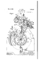
- Figure 1 is an elevation of an engine having two rotors and constructed in accordance with this invention; and shows the mechanism for operating the inlet and exhaust valves; parts are broken away to expose internal construction.
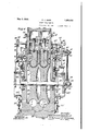
- Fig. 2 is a vertical section on line :02, Figs. 1, 3, and 5, looking in the direction of the arrow and showing some of the parts intact, parts are broken away to expose parts otherwise hidden.
- Fig. 3 is an elevation mainly in section on line 003, Figs. 2 and 5, of the engine shown in Fig. 1, the parts in section being shown with the live steam inlet valve closed, and with the exhaust valve just on the point of admitting to the abutment lifting piston steam exhausting from between the piston and the abutment; broken lines indicate a position for allowing exhaust steam to operate the abutment lifting piston; and dotted lines indicate a position of the oscillating valve during the down stroke of the abutment; portions of the parts which are shown sectioned on line 4123, are broken away to expose non-sectioned parts of the companion motor.
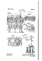
- Fig. 4 is a fragmental detail showing the exhaust valve in position cutting off the exhaust steam from the abutment lifting piston. and opening the main exhaust valve.
- Fig. 6 is a fragmental detail of the oscillating exhaust valves on line 006, Figs. 1 and 3, showing one of the exhaust valves open, and the other exhaust valve closed.
- Fig. 7 is a fragmental section on line 007, Fig. 3, showing one rotor piston in power position and the piston way for the other piston free.
- Fig. 8 is a fragmental section of the intake valve on line m8, Fig. 3.
- Fig. 9 is fragmental detail on a larger scale, of a well known form of dash-pot operated intake valve cut-off releasing gear, showing the head of the dash-pot connecting rod as it is being raised, and as the intake valve is starting to open for admitting live steam to the steamway; broken lines indicate a position just after the head of the dash-pot has been released to allow the cut-off valve to be closed.
- the suitably journalled rotor shaft 1 is provided with a peripherally grooved rotor 2, the groove 3 of which extends almost entirely around the rotor and is interrupted by a piston 4 which projects from the rotor into an annular groove 5 in the stationary frame or stator which may be made up of sections as indicated at 6, 6', and which is constructed to form a housing for parts of the engine.
- Said groove 3 in the rotor serves as a steamway
- the groove 5 in the frame serves as a steam-way and piston-way.
- a vertical steam way 5 for a reciprocating abutment 7 which istimed by suitable means to enter the unitary steam channel formed by the grooves afterthe piston has passed the abutment, and is adapted and arranged to'reciprocate in the abutment way 5', and to be withdrawn from the grooves to allow the piston. to pass at the close of a complete revolution.
- the piston 4 is preferably a separable part of the rotor and is shown in Fig. 3 as set into a transverse slot 8 in the rotor and secured therein byv a bolt 9 inserted through-a side of the rotor and screwed into the reduced shank .10 of the piston; and said piston is provided with grooves 11 and packing rings 12 seated therein and adapted to fit the walls of the steam grooves to make a steam tight joint.
- the abutment 7 is also provided with grooves 13 and packing rings 14 secured in said grooves to prevent steam leakage.
- the rotor is shown provided with a piston supporting lug'15 having a sloping forward face 16 and a rearward piston supporting face 17 against which the piston is detachably secured by said bolt 9.
- the piston is preferably provided with a rear face 18 that extends across the steam way and is slightly divergent outwardly from the forward face of the abutment so that when the abutment is in place and the piston is adjacent thereto, and in front thereof, steam may be admitted, into the steamway 5 through a notch 19 in the abutment, to which notch the steam is supplied through a port 20 from a rotary valve 21 that is timed in accordance with the purpose of the constructor to cut off the steam at a certain point when a sufficient amount ofsteam has entered the steam-way behind the piston to drive said piston around to the exhaust position.
- the reciprocating abutment 7 is shown connected by a connecting rod 22 to a piston head 23 which works in the cylinder 24, to
- valve 30' to a live steam pipe 31 which is normally closed by a valve 32 and may be opened to the steam supply pipe 33,
- valve 34 is the main exhaust port controlled by the valve limb 28 and leading to an exhaust steam abutment-operating cylinder 35.
- the two valve limbs 27 and 28 are spaced apart a distance practically equal to the space between the ports of the exhaust passages 29 and 34 sothat in one position of the exhaust valve, the ports 29. and 34 are covered; and said valves are timed to allow this to occur when the abutment 7 is down as indicated in Fig. 3, and the lug and piston on the rotor are closely approaching the abuting-mechanism is arranged to shift the twolimbed valve to the position indicated in Fig. 4, immediately after the rotor piston 4 has passed the abutment 7.
- a direct exhaust passage located between the ports of passages 29 and 34.
- Said direct exhaust passage leads to the exhaust pipe 37 which at the final position of the duplex valve, is open directly to the exhaust passage 25; and the flow of the exhaust steam in the exhaust pipe 37 is thus unobstructed to the final exhaust pipe 38 which is constantly open to the abutment depression chamber 35.
- the upper end of the abutment 7 constitutes a piston head 39 having packthe depression cylinder 35 above the piston head 39 of the Lip-lifted abutment, said abutment, will be driven down because the exhaust steam through abutment lifting exhaust passage 29 has been cut off;
- the passage 29 is open to the direct exhaust passage 36; and the passage 34, being open to the exhaust'pipe 38, the exhaust steam pressure in cylinder 35 drives the abutment down, and upon further oscillation ofthe two limbed valve 26 to the position shown in Fig. 4, with the limb 28 between the passages 29 and 36, the flow of exhaust steam is directly from the passage 25 to the direct exhaust passage 36; and the abutment remains depressed until the revolution of the rotor has brought the abutment again into the position shown in Fig. 3.
- the final exhaust pipe 38 is provided with a regulating valve 41 which may be adjusted to form a measurable obstruction to the final exhaust of the exhaust steam at each moment of depressing the abutment.
- valve 32 may be turned to close the live steam inlet pipe 33 and to open the pipe 31. Then the valve 30 may be opened and the steam entering the cylinder 24 below the piston head 23 will withdraw the abutment from the steam-way formed by grooves 3 and 5.
- the intakevalve 21 is journalled in its valve chamber 21 and is operable by the intake valve shaft 71 that is connected through suitable valve timing mechanism with the rotor shaft 1.
- Said timing mechanism is shown as consisting of an assembly comprising a crank 78, on the shaft 71, a connecting rod 7 8 connected with an eccentric ring 79 on eccentric 80, fixed to and rotating with the rotor shaft 1, the connecting rod 78 being connected to the radius bar 81 mounted on the stationary pin 82.
- the by-pass 37 meanwhile, connects the vent 36 with the open air through the exhaust pipe; and after the valve. 34 begins to return clockwise from the position of Fig. 4, the pressure of exhausting steam will still be applied through 34 until the valve has reached the solid line position shown in Fig. 3; then by a further slight oscillation the ex hausting steam valve reaches the position shown in dotted lines in Fig.
- stator being provided with an exhaust valve chamber open to the exhaust passage, an exhaust outlet open from the exhaust valve chamber to the abutment Way above the piston; an exhaust way open from the exhaust valve chamber to the exhaust cylinder to supply exhaust steam to operate the piston head'to lift the abutment; a valve inthe exhaust valve chamber; and means timed with different positions of thepistonand to position the valve to close both of said exhaust ways at'another position ofthe'piston.
- An engine comprising a rotor shaft, ,a peripherally grooved rotor fixed to said shaft and having a groove which extends'almost entirely around the rotor, a piston in the groove and projecting from the rotor, a-stator having an annular groove and constituting a housing,'the grooves in the rotor and stator serving as annular steam and piston Way, said stator and rotor being also provided with a.
- the grooves .forming a unitary channel into which the abutment way opens, a reciprocating abutment in the abutment w,ay,'means for moving the abutment into and out of the channel, means timed with the rotor to cause the abutment to enter the unitary channel formed betwen grooves after the piston has passed, said timed means being adapted and arranged to withdraw the abutment from the channel to allow the piston to pass the abutment way the end of a complete revolution, means to supply steam to the channel betweenthe piston and the abutment after the'piston' has passed the abutment way and theabutment has closed the channel, means timed with the rotor-to allow spent steam to be'exhausted from between the piston and the abutment before the piston passes the abutment way, two cylinders aligned with the abutment and separat ond cylinder, a piston headconnected to the piston rod and
Landscapes
- Engineering & Computer Science (AREA)
- Mechanical Engineering (AREA)
- General Engineering & Computer Science (AREA)
- Engine Equipment That Uses Special Cycles (AREA)
Description
May 3, 1932.
E. C. DUER ROTARY STEAM ENGINE Filed Oct. 20-, 1928 5 Sheets-Sheet 1 Edward C/zrzlriikuzfluar" W7 b .May 3, 1932. E. c. DUER 1,856,542 ROTARY STEAM ENGINE Filed-Oct. 20, 1928 5 Sheets-Sheet s V Z4 fig 7" 37 T.
40 Exmw Inventor May 3, 1932.
I ROTARY STEAM ENGINE Fild Oct. 20, 1928 5 Sheets-Sheet 4 2 I rzventqr witnesses Edward 67226222211 Utter gcvmmwywmm 41 Z3. W at E. c. DUER I 1,856,542 7 Patented May 3, 1932 PATENT @FFECE EDWARD CHRISTIAN DUER, 0]? LOS ANGELES, CALIFORNIA ROTARY STEAM ENGINE Application filed October 20, 1928.
An object of this invention is to provide a simple rotary steam engine adapted to obtain from steam or other expansive fluid, by single expansion, the maximum amount of power that may be developed from such fluid medium. I
' Another object is to provide practical means for packing against leakage of steam, gas or vapor used.
Simplicity and cheapness of construction, and economy and certainty of operation, are other objects of invention.
The invention is applicable with a single cylinder and piston, but in order to avoid the dependence upon momentum to carry the piston past dead center, the invention is preferably embodied in couples of motors on a single shaft.
The invention is broadly new, basic and pioneer in that a reciprocating abutment and a revolving piston are combined with means for admitting the expansive medium between the piston and the abutment at one position of the rotor which carries the pistomand means whereby the expanded medium is released after almost a full revolution of the piston has been eitected.
Another broadly new and basic feature of the invention is the operation of the reciprocating abutment by the steam exhaust.
Another object is to make provision whereby the revolution of the rotor by momentum of the engine at the time of stopping will be unobstructed.
An object is to provide a cheap and simple governor controlled rotary engine. It is understood that with a suitable condenser, mercury vapors may beused as a power medium instead of steam. 7
An object is to make provision whereby the live steam abutment may-be withdrawn from and returned to the live steam way by pressure of exhaust steam which would otherwise be wasted, and without mechanically operated parts, for lifting the abutment.
Other objects, advantages and. features of invention may appear from the accompanying drawings, the subjoined detailed description and the appended claims.
Serial No. 313,743.
Figure 1 is an elevation of an engine having two rotors and constructed in accordance with this invention; and shows the mechanism for operating the inlet and exhaust valves; parts are broken away to expose internal construction.
Fig. 2 is a vertical section on line :02, Figs. 1, 3, and 5, looking in the direction of the arrow and showing some of the parts intact, parts are broken away to expose parts otherwise hidden. i
Fig. 3 is an elevation mainly in section on line 003, Figs. 2 and 5, of the engine shown in Fig. 1, the parts in section being shown with the live steam inlet valve closed, and with the exhaust valve just on the point of admitting to the abutment lifting piston steam exhausting from between the piston and the abutment; broken lines indicate a position for allowing exhaust steam to operate the abutment lifting piston; and dotted lines indicate a position of the oscillating valve during the down stroke of the abutment; portions of the parts which are shown sectioned on line 4123, are broken away to expose non-sectioned parts of the companion motor.
Fig. 4 is a fragmental detail showing the exhaust valve in position cutting off the exhaust steam from the abutment lifting piston. and opening the main exhaust valve.
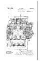
Fig. 5 is a plan of the engine shown in Fig. 1.
Fig. 6 is a fragmental detail of the oscillating exhaust valves on line 006, Figs. 1 and 3, showing one of the exhaust valves open, and the other exhaust valve closed.
Fig. 7 is a fragmental section on line 007, Fig. 3, showing one rotor piston in power position and the piston way for the other piston free.
Fig. 8 is a fragmental section of the intake valve on line m8, Fig. 3.
Fig. 9 is fragmental detail on a larger scale, of a well known form of dash-pot operated intake valve cut-off releasing gear, showing the head of the dash-pot connecting rod as it is being raised, and as the intake valve is starting to open for admitting live steam to the steamway; broken lines indicate a position just after the head of the dash-pot has been released to allow the cut-off valve to be closed.
Fig. 10 is a fragmental detail on alarger scale than Fig. 9, of the usual dash-pot construction.
The suitably journalled rotor shaft 1 is provided with a peripherally grooved rotor 2, the groove 3 of which extends almost entirely around the rotor and is interrupted by a piston 4 which projects from the rotor into an annular groove 5 in the stationary frame or stator which may be made up of sections as indicated at 6, 6', and which is constructed to form a housing for parts of the engine. Said groove 3 in the rotor serves as a steamway, and the groove 5 in the frame serves as a steam-way and piston-way. and the ways 3 and 5 are open to a vertical steam way 5 for a reciprocating abutment 7 which istimed by suitable means to enter the unitary steam channel formed by the grooves afterthe piston has passed the abutment, and is adapted and arranged to'reciprocate in the abutment way 5', and to be withdrawn from the grooves to allow the piston. to pass at the close of a complete revolution.
The piston 4 is preferably a separable part of the rotor and is shown in Fig. 3 as set into a transverse slot 8 in the rotor and secured therein byv a bolt 9 inserted through-a side of the rotor and screwed into the reduced shank .10 of the piston; and said piston is provided with grooves 11 and packing rings 12 seated therein and adapted to fit the walls of the steam grooves to make a steam tight joint.
' The abutment 7 is also provided with grooves 13 and packing rings 14 secured in said grooves to prevent steam leakage.
The rotor is shown provided with a piston supporting lug'15 having a sloping forward face 16 and a rearward piston supporting face 17 against which the piston is detachably secured by said bolt 9.
The piston is preferably provided with a rear face 18 that extends across the steam way and is slightly divergent outwardly from the forward face of the abutment so that when the abutment is in place and the piston is adjacent thereto, and in front thereof, steam may be admitted, into the steamway 5 through a notch 19 in the abutment, to which notch the steam is supplied through a port 20 from a rotary valve 21 that is timed in accordance with the purpose of the constructor to cut off the steam at a certain point when a sufficient amount ofsteam has entered the steam-way behind the piston to drive said piston around to the exhaust position.
The reciprocating abutment 7 is shown connected by a connecting rod 22 to a piston head 23 which works in the cylinder 24, to
through valve 30'to a live steam pipe 31 which is normally closed by a valve 32 and may be opened to the steam supply pipe 33,
to admit to cylinder 24 below the abutment,
live steam, for lifting piston 23 to positively hold the abutment up so that the rotor may revolve unobstructedly under the momentum of the rotor and connected machinery at the stopping operation.
34 is the main exhaust port controlled by the valve limb 28 and leading to an exhaust steam abutment-operating cylinder 35. The two valve limbs 27 and 28 are spaced apart a distance practically equal to the space between the ports of the exhaust passages 29 and 34 sothat in one position of the exhaust valve, the ports 29. and 34 are covered; and said valves are timed to allow this to occur when the abutment 7 is down as indicated in Fig. 3, and the lug and piston on the rotor are closely approaching the abuting-mechanism is arranged to shift the twolimbed valve to the position indicated in Fig. 4, immediately after the rotor piston 4 has passed the abutment 7.
36 is a direct exhaust passage located between the ports of passages 29 and 34. Said direct exhaust passage leads to the exhaust pipe 37 which at the final position of the duplex valve, is open directly to the exhaust passage 25; and the flow of the exhaust steam in the exhaust pipe 37 is thus unobstructed to the final exhaust pipe 38 which is constantly open to the abutment depression chamber 35. The upper end of the abutment 7 constitutes a piston head 39 having packthe depression cylinder 35 above the piston head 39 of the Lip-lifted abutment, said abutment, will be driven down because the exhaust steam through abutment lifting exhaust passage 29 has been cut off;
and when the valve has first uncovered the ports 29 and 34, the passage 29 is open to the direct exhaust passage 36; and the passage 34, being open to the exhaust'pipe 38, the exhaust steam pressure in cylinder 35 drives the abutment down, and upon further oscillation ofthe two limbed valve 26 to the position shown in Fig. 4, with the limb 28 between the passages 29 and 36, the flow of exhaust steam is directly from the passage 25 to the direct exhaust passage 36; and the abutment remains depressed until the revolution of the rotor has brought the abutment again into the position shown in Fig. 3.
The final exhaust pipe 38 is provided with a regulating valve 41 which may be adjusted to form a measurable obstruction to the final exhaust of the exhaust steam at each moment of depressing the abutment.
In case it is desired to positively hold the abutment out of the path of the rotor lug, the valve 32 may be turned to close the live steam inlet pipe 33 and to open the pipe 31. Then the valve 30 may be opened and the steam entering the cylinder 24 below the piston head 23 will withdraw the abutment from the steam-way formed by grooves 3 and 5.
The exhaust valve 26 is journalled in its valve chamber 26 and is operable by a shaft 42 that is connected through suitable valve timing mechanism with the rotor shaft 1. Said mechanism is shown as consisting of an assembly comprising a crank 43, on the shaft 42, a connecting rod 44, an oscillator 45 journalled on a fixed shaft 46 and provided with a wrist pin 47 connected by a connecting rod 48 with an eccentric ring 49 on eccentric 50,
fixed to and rotating with the rotor shaft 1,
the connecting rod being connected to the radius bar 51 mounted on the stationary pin 52, a wrist pin 53 fixed to the oscillator 45. and the connecting rod 44 that is adjustablv connected with the crank 43 by a pin and slot adjustment 54, 55, for greater or less throw of the valve as may be desired for regulation of the stroke.
The speed governing mechanism is shown as a train consisting of a beveled gear 56 fixed to the end of the rotor shaft 1, a second beveled gear 57 in mesh therewith, connecting shaft 58 journalled in the housings 59, 59 and brackets 60 that are fixed to the frame members 6' and 6; said connecting shaft 58 way to lift the head 75 of the connecting rod 76 of the dash pot 77.
The intakevalve 21 is journalled in its valve chamber 21 and is operable by the intake valve shaft 71 that is connected through suitable valve timing mechanism with the rotor shaft 1. Said timing mechanism is shown as consisting of an assembly comprising a crank 78, on the shaft 71, a connecting rod 7 8 connected with an eccentric ring 79 on eccentric 80, fixed to and rotating with the rotor shaft 1, the connecting rod 78 being connected to the radius bar 81 mounted on the stationary pin 82.
In the foregoing description of the operation, reference has been made to steam as the power medium, but it is understood that the apparatus is especially adapted to the use of mercury vapor as it is practical to confine the vapors and to return them to the condenser and thence to a heating apparatus, not shown, and then to the circuit above described.
It is understood that in the appended claims the term steam is not used in a limiting sense, but for convenience as the utilization of mercury vapors or any other expansive fluid is contemplated as equivalents of steam, and it is not deemed necessary to illustrate herein the steam boiler or other means whereby the heat is applied, or the condensation of the spent vapors or exhaust stem is effected, as such apparatus is well understood in the art.
The stator is provided with drain passages 83, 84 leading to a drain pipe 85 provided with a valve 85' that may be opened to carry off any water of condensation that might in time result from the leakage of any steam of the rotor cavity 86 of the stator.
The practical operation will be understood by reference to the drawings. Starting with the dotted position shown in Fig. 2, when live steam is admitted through valve 32 to oscillating live steam valve 21, and said valve 21 is in the dotted open position to admit steam through the port 19 into the live steam way 3, 5 on the right hand side of the abutment 7 as shown in Fig. 3, between the abutment 7 and the piston 4, the piston will be driven by live steam to the broken line position shown in Fig. 3 and then the valve 21 will be closed and expansion of the steam between the piston and the abutment will drive the piston clockwise to the solid line position of the piston shown at the left of the rotor.
During this period of rotation the arms 27, 28 of the oscillating exhausting steam valve will be moving from the solid line position in Fig. 3 to the position shown in Fig. 4 and during all this time after the limb 28 has withdrawn from the port 34, the port 29 will be closed to the exhausting steam and the port 34 opened to such steam so that the exhausting steam from in front of the piston will escape through the passage 25 and the port 34 to create pressure in the chamber 35 .from 'which chamber the exhausting steam may pass through the exhaust pipe 38 to the atmosphere. 1
The by-pass 37, meanwhile, connects the vent 36 with the open air through the exhaust pipe; and after the valve. 34 begins to return clockwise from the position of Fig. 4, the pressure of exhausting steam will still be applied through 34 until the valve has reached the solid line position shown in Fig. 3; then by a further slight oscillation the ex hausting steam valve reaches the position shown in dotted lines in Fig. 3, the valve will close the port34 to the exhausting steam and v will open the upper port 29 to momentarily admit exhausting steam beneath the piston head 23, and the expansive force of such exhausting steam will then operate the abutment piston head 23 to lift theabutment out of the steam way 3, 5 so that the piston 4 may pass; and then immediately after the piston 4 has passed the abutment, the oscillating exhausting steam valve will have again uncovered the port 34 to the exhausting I steam, and will'have shut off such steam from port 29 so that the abutment is again returned by pressure of exhausting steam, to the position shown in Fig. 3; and instantly the valve 21 opens to allow live steam to enter between the abutment and the piston, whereupon the cycle first described will be repeated.
The by-pass through 36, 37 to the exhaust pipe38 allows admission of air to the port 29 so that the abutment piston 23 may move readily Without producing any vacuum and/ 1 ed by a partition, a pistonrod connected to hausting steam valve are timed by the eccentric'on the shaft 1, through eccentric rod 48, disc 45, connecting rod 44, crank 43 and shaft 42.
to the rotor and fitting the steam way; an
abutment reciprocating in the abutment way and provided at one end with a piston head; said stator being provided with an exhaust valve chamber open to the exhaust passage, an exhaust outlet open from the exhaust valve chamber to the abutment Way above the piston; an exhaust way open from the exhaust valve chamber to the exhaust cylinder to supply exhaust steam to operate the piston head'to lift the abutment; a valve inthe exhaust valve chamber; and means timed with different positions of thepistonand to position the valve to close both of said exhaust ways at'another position ofthe'piston.
2. An engine, comprising a rotor shaft, ,a peripherally grooved rotor fixed to said shaft and having a groove which extends'almost entirely around the rotor, a piston in the groove and projecting from the rotor, a-stator having an annular groove and constituting a housing,'the grooves in the rotor and stator serving as annular steam and piston Way, said stator and rotor being also provided with a. way for 'a reciprocating abutment, the grooves .forming a unitary channel into which the abutment way opens, a reciprocating abutment in the abutment w,ay,'means for moving the abutment into and out of the channel, means timed with the rotor to cause the abutment to enter the unitary channel formed betwen grooves after the piston has passed, said timed means being adapted and arranged to withdraw the abutment from the channel to allow the piston to pass the abutment way the end of a complete revolution, means to supply steam to the channel betweenthe piston and the abutment after the'piston' has passed the abutment way and theabutment has closed the channel, means timed with the rotor-to allow spent steam to be'exhausted from between the piston and the abutment before the piston passes the abutment way, two cylinders aligned with the abutment and separat ond cylinder, a piston headconnected to the piston rod and working in the second cylinder, said abutment being formed as a piston working in they first cylinder and means timed with the rotor to deliver exhaust steam from the steam way to the second cylinder to operate the piston head and from the steam way to the first cylinder to depress the abutment.
In testimony whereof I have hereunto set my hand at Los Angeles, California, this 27th day of September, 1928.
EDWARD CHRISTIAN DUER.
ill.
' iii
Priority Applications (1)
| Application Number | Priority Date | Filing Date | Title |
|---|---|---|---|
| US313743A US1856542A (en) | 1928-10-20 | 1928-10-20 | Rotary steam engine |
Applications Claiming Priority (1)
| Application Number | Priority Date | Filing Date | Title |
|---|---|---|---|
| US313743A US1856542A (en) | 1928-10-20 | 1928-10-20 | Rotary steam engine |
Publications (1)
| Publication Number | Publication Date |
|---|---|
| US1856542A true US1856542A (en) | 1932-05-03 |
Family
ID=23216954
Family Applications (1)
| Application Number | Title | Priority Date | Filing Date |
|---|---|---|---|
| US313743A Expired - Lifetime US1856542A (en) | 1928-10-20 | 1928-10-20 | Rotary steam engine |
Country Status (1)
| Country | Link |
|---|---|
| US (1) | US1856542A (en) |
-
1928
- 1928-10-20 US US313743A patent/US1856542A/en not_active Expired - Lifetime
Similar Documents
| Publication | Publication Date | Title |
|---|---|---|
| US2468451A (en) | Rotary internal-combustion engine | |
| US1856542A (en) | Rotary steam engine | |
| US2766737A (en) | Injection valve for rotary type internal combustion engine | |
| US2297529A (en) | Rotary motor | |
| US678338A (en) | Rotary engine. | |
| US2248484A (en) | Heat energized apparatus | |
| US2550849A (en) | Rotary engine | |
| JP6152993B2 (en) | Rotary engine and method | |
| US1016129A (en) | Rotary engine. | |
| US2037358A (en) | Reversible fluid pressure motor | |
| US3080722A (en) | molnar | |
| US2176812A (en) | Rotary engine | |
| US1725881A (en) | Apparatus for operating liquid turbines by means of combustion machines | |
| US1201383A (en) | Steam-engine. | |
| US951479A (en) | Rotary engine. | |
| US2608960A (en) | Sliding abutment type rotary internal-combustion engine | |
| US2078887A (en) | Rotary internal combustion engine | |
| US1738320A (en) | Rotary engine | |
| US1867917A (en) | Combustion rotary engine | |
| US2037351A (en) | Reversible rotary motor | |
| US979435A (en) | Vacuum steam-engine. | |
| US1363423A (en) | Rotary gas-engine | |
| US962850A (en) | Rotary engine. | |
| US1835543A (en) | Starting mechanism for internal combustion engines | |
| US1310735A (en) | Planoqraph co |