US1856532A - Outrigger frame, fore and aft control type airplane - Google Patents
Outrigger frame, fore and aft control type airplane Download PDFInfo
- Publication number
- US1856532A US1856532A US380126A US38012629A US1856532A US 1856532 A US1856532 A US 1856532A US 380126 A US380126 A US 380126A US 38012629 A US38012629 A US 38012629A US 1856532 A US1856532 A US 1856532A
- Authority
- US
- United States
- Prior art keywords
- frame
- elevator
- airplane
- fore
- outrigger
- Prior art date
- Legal status (The legal status is an assumption and is not a legal conclusion. Google has not performed a legal analysis and makes no representation as to the accuracy of the status listed.)
- Expired - Lifetime
Links
- 230000009471 action Effects 0.000 description 4
- 238000010276 construction Methods 0.000 description 4
- 230000000694 effects Effects 0.000 description 4
- 230000006872 improvement Effects 0.000 description 4
- 238000006243 chemical reaction Methods 0.000 description 3
- 230000001627 detrimental effect Effects 0.000 description 3
- 230000007547 defect Effects 0.000 description 2
- 239000000463 material Substances 0.000 description 2
- 230000003387 muscular Effects 0.000 description 2
- 101100536354 Drosophila melanogaster tant gene Proteins 0.000 description 1
- 230000006978 adaptation Effects 0.000 description 1
- 238000012550 audit Methods 0.000 description 1
- 230000003190 augmentative effect Effects 0.000 description 1
- 230000008878 coupling Effects 0.000 description 1
- 238000010168 coupling process Methods 0.000 description 1
- 238000005859 coupling reaction Methods 0.000 description 1
- 238000010586 diagram Methods 0.000 description 1
- IWEDIXLBFLAXBO-UHFFFAOYSA-N dicamba Chemical compound COC1=C(Cl)C=CC(Cl)=C1C(O)=O IWEDIXLBFLAXBO-UHFFFAOYSA-N 0.000 description 1
- 238000004519 manufacturing process Methods 0.000 description 1
- 230000007246 mechanism Effects 0.000 description 1
- 230000004048 modification Effects 0.000 description 1
- 238000012986 modification Methods 0.000 description 1
- 230000007935 neutral effect Effects 0.000 description 1
- 230000008520 organization Effects 0.000 description 1
- 230000003071 parasitic effect Effects 0.000 description 1
- 230000002787 reinforcement Effects 0.000 description 1
- 230000003014 reinforcing effect Effects 0.000 description 1
- 230000004044 response Effects 0.000 description 1
- 238000007493 shaping process Methods 0.000 description 1
- 125000006850 spacer group Chemical group 0.000 description 1
- 239000003381 stabilizer Substances 0.000 description 1
- 230000003068 static effect Effects 0.000 description 1
- 238000005728 strengthening Methods 0.000 description 1
Images

Classifications
-
- B—PERFORMING OPERATIONS; TRANSPORTING
- B64—AIRCRAFT; AVIATION; COSMONAUTICS
- B64C—AEROPLANES; HELICOPTERS
- B64C13/00—Control systems or transmitting systems for actuating flying-control surfaces, lift-increasing flaps, air brakes, or spoilers
Definitions
- This invention relates to airplanes and particularly to the outrigger, fore-and-aft controltype, and has reference to important mprovements relating to the construction, liftefficiency and manual control of the type of airplane shown in Blondin Patent No. 1,240,- 812, of September 25, 1917.
- the present invention has numerous ob] ects among which are to provide a design of unit "side-frame which reinforces and strengthens in important aspects; to provide a novel combination of the side-frames in their relation to accomplish a particular function by a novel shaping of the elements of the side-frames: to introduce a new and stiffening structural feature; to provide an arrangement of control means whereby to materially reduce the manual efiort of their operation and to increase the efficiency of the fore-and-aft control of the machine as a'whole. Also, to provide a new principle of coupling and operation of the fore-and-aft control.
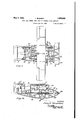
- Figure l is a top plan of the airplane.
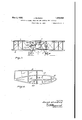
- Figure 2 is a side elevation thereof.
- Figure 3 is a front elevation thereof.
- Figure 4 is a side elevation of one of the unit side-frames.
- Figure 5 illustrates an end-bolted, two pole strut construction of conventional form.
- Figure 6 is a side elevation of a unit-frame strut and motor combination.
- Figure 7 illustrates a conventional control mount.
- Figure 8 is a perspective of my improved control mount.
- Figure 9 is a diagrammatic illustration of positions of the control surfaces.
- Figure 10 is a diagram showing the system of connected elevator controls.
- FIGS 11 and 12 are detail views.
- the main frame of the airplane consists of a pair of rigid-structure, skeleton, sideframes 1 and 2 each of which comprises a main longitudinal component 19 which extends forward and rearward of uprights 16 which extend upward and carry a ridge element 15 that extends well to the rear and as shown in Figures 1 and 3 constitutes a double ridge when the side-frames are secured in downward and outward angular relation, or A-form.
- a ridge element 15 that extends well to the rear and as shown in Figures 1 and 3 constitutes a double ridge when the side-frames are secured in downward and outward angular relation, or A-form.
- an inverted arcuate skid strip 22 along the lower ends of the uprights 16 of each side frame is joined an inverted arcuate skid strip 22 and this is provided with arch braces 10-10 reaching up to the element 19 and disposed fore-andaft of ground-wheels W.
- the skids 22 extend forward of the main elements 19 and curve upward to form a forerig which includes arch strips 21 intersecting the main uprights 16 and running rearward and downward to form a rear outrigger structure including rudder post-s 2a.
- These posts here consist of vertical parts of unit-strut frames 24 stepped on the rear ends of the elements, 19, Figure 2 and which, with the rear end of the united ridge beams 15, support the fixed stabilizer S to the rear of which is hinged the rear elevator 7.
- the uprights 16 are supplemented by a forward brace 16 reaching from skid 22 to arch 21 and abutted by the main element 19, and'other uprights 16" tie all longitudinal elements of each unit side-frame.
- the arch member 1010 has the impor tant function of reinforcing and strengthening the strut and skid frame adjacent to the front elevator and underlies and reinforces that portion of the side frame which supports the lower wing 4, and at its rear end reinforces and stifiens the skid frame at its normal point'of land contact when at rest and when landing.
- a feature of my present invention is in improvingv the elevator 6 by hinging its foreedge to the leading cross-beam 25, whereby, it is seen,,any upwardgust of air can'have no other efleot than to raise the elevator surface rearward of-the'beamthus automatically forcing the elevator intoan attitude that steers the airplane; down or in opposition to the air'gust. Conversely, any air gust from above automatically increasesthe ele- -vator"s-.angle and steers the airplane upward or in oppo'sitionto the gust.
- My remedy forthis detrimentalaction of fore-and-aft controls is to couple asaid. controls differentially; reducing the-angularity of travel of the front elevator with relation to the rear elevator to'suchan extent that when the rear elevator reaches its attitude of zero-anglewith relation to the line of flight Z, Fig. 9, thefront elevator shallnothave reachedits burble-point or angle where its effective lift becomes subordinate. to its detrimental -drag, whereby the front elevator shall continue to be a continually effective control element.
- the present disclosure embodies the unit-frame system of frame or skeleton in such combination as to constitute the chassis or foundation of the whole design, entirely independent of the wing structure, and which is shown in the above mentioned patent, and includes a new and important improvement wherein the side-frame units 1 and 2 are inclined inward and upward from the skid line and have their ridge components lapped longitudinally into a rigid ridge beam 15.
- the spaced main longitudinals 19 of the side frames are rigidly secured by the horizontal cross beams 18 disposed well toward the skid plane and thus forming a triangularly trussed chassis, as shown in Fig. 3.
- All of the component limbs of this A-frame chassis instead of being stream-lined in section 00, Fig. 11, are now cambered or given a wing cross section w, Fig. 12. This is for the purpose of giving a material lift resultant to the machine as well as the primary frame-forming function. In the larger types of machines the limbs may be so proportioned as to lift their own weight or even contribute to the surplus or pay-load lift of the machine.
- FIG. 5 shows how a conventional interplane post strut P whose incidence wires are depended upon to maintain the proper flying-angle of the wings relative to the machine as a whole, is poorly adapted for such a purpose, particularly when any other than flying stresses are imposed on the post struts, under the best of normal flying conditions these incidence wires, however well they may be tuned and aligned at the beginning of a flight, will, and inevitably dogive under the influences of torsional stresses in the wings and the effect of heat,
- I provide a window-frame strut 30 of the type shown in said patent, with which is compower plant and the driven propeller all set outboard from the car body as designed for multimotor, transport planes.
- the rigidity of the shell and unit frame strut structure constitutes high factor of strength and safety in connecting the upper wing 3 to the lower Wing 4:.
- outrigger type airplanes whereby the framework of the machine is so fashioned as to constitute a unit chassis to unite, strengthen, and support all other elements and whereby the several frame limbs are given a lifting effect profile: and, further, improve the stability and control of balance in flight, and provide a plane which is superior in points of simplicity, strength, design and organization, positiveness of action, safety and general efficiency.
- outrigger structure comprising right and left side, integral skeleton frames which incline inwardly and upwardly and join to form a ridge beam and whose lower spread sides are rigidly joined by transverse horizontal beams; thereby forming a triangular, trussed unit chassis whose lowermost, lateral longitudin als form land skids.
- outrigger framework unit-chassis consisting of a system of flat skeleton frames set in A-form relation and whose limbs are of wing or lift camber-section.
- outrigger framework forming an upright triangular truss which supports and interconnects all other elements of the airplane as a whole, and provides an A-form unitary chassis for ready attachment and detachment of its Wings to and from the apex of the truss to facilitate storage in restricted space.
- transverse tie-beams and vbovvsprit frame laid on said beams and forming a transverse and longitudinal reinforcement for'the chass1s.- r '7'.
- an interplane frame-strut including upright and top and bottom members of rigid,'permanent structure for determining fixed wing-incidence, and a power plant shell'mounted for'rigid support on the uprights of the frame-strut the uprights being relatively immovable.
- a power plant including 'a'streamline shell'which is mounted in, and in the plane of and forms a rigid part of an interplane strut of rigid window frame structure free of incidence wires.
Landscapes
- Engineering & Computer Science (AREA)
- Automation & Control Theory (AREA)
- Aviation & Aerospace Engineering (AREA)
- Toys (AREA)
Description
May 3, 1932. J. agouom 1356,5132
OUTRIGGER FRAME, FORE Am) AFT CONTROL TYPE AIRPLANE- Filed July 22, 1929 s Sheets-Sheet 1 I I] /z INVENTOR, 755G707? Bionaflz'n;
ATTORN y J. BLONDIN 1,856,532
' 'OU'I'RIGGER FRAME, FORE AND AFT CONTROL TYPE AIRPLANE Filed July 22, 1929 3 Sheets-Sheet 2 INVENTOR, Jake v77 870714272 W TTORNEYJ.
y 1932- J.BLONDIN 1,856,532
OUTRIGGER FRAME, FORE AND AFT CONTROL TYPE AIRPLANE FiledJuly 22, 1929 s Sheets-Sheet 5 INVENTOR,
A TTORNEY' Patented May 3, 1932 UNITED STATES JOSEPH BLONDIN, OF LOS ANGELES, CALIFORNIA OUTRIGGER FRAME, FORE AND AFT CONTROL TYPE AIRPLANE Application filed July 22, 1929. Serial No. 380,126.
This invention relates to airplanes and particularly to the outrigger, fore-and-aft controltype, and has reference to important mprovements relating to the construction, liftefficiency and manual control of the type of airplane shown in Blondin Patent No. 1,240,- 812, of September 25, 1917.
Such patent discloses the principle of unit frame construction embodied in its side-frame 1 elements and its interplane struts.
The present invention has numerous ob] ects among which are to provide a design of unit "side-frame which reinforces and strengthens in important aspects; to provide a novel combination of the side-frames in their relation to accomplish a particular function by a novel shaping of the elements of the side-frames: to introduce a new and stiffening structural feature; to provide an arrangement of control means whereby to materially reduce the manual efiort of their operation and to increase the efficiency of the fore-and-aft control of the machine as a'whole. Also, to provide a new principle of coupling and operation of the fore-and-aft control. surfaces whereby these are moved through paths of predetermined unequal extent, or differentially, and whereby the aerodynamic efiiciency of the controls is materially improved. The general purpose of these improvements is to contribute to the production of airplanes of increased strength and rigidity, of increased lift capacity and of control and more safety in flight, applying more particularly to large transport airplanes of the multi-motor type. Additional objects, advantages and features and principles of construction and mode of operation will be made manifest in the ensu- 6 ing description of the herewith illustrated em bodiment; it being understood that modifications, variations and adaptation may be re sorted to within the spirit, scope and principle of the invention as it is more directly hereinafter claimed.
Figure l is a top plan of the airplane.
Figure 2 is a side elevation thereof.
. Figure 3 is a front elevation thereof.
Figure 4 is a side elevation of one of the unit side-frames.
Figure 5 illustrates an end-bolted, two pole strut construction of conventional form.
Figure 6 is a side elevation of a unit-frame strut and motor combination.
Figure 7 illustrates a conventional control mount.
Figure 8 is a perspective of my improved control mount.
Figure 9 is a diagrammatic illustration of positions of the control surfaces.
Figure 10 is a diagram showing the system of connected elevator controls.
Figures 11 and 12 are detail views.
The main frame of the airplane consists of a pair of rigid-structure, skeleton, sideframes 1 and 2 each of which comprises a main longitudinal component 19 which extends forward and rearward of uprights 16 which extend upward and carry a ridge element 15 that extends well to the rear and as shown in Figures 1 and 3 constitutes a double ridge when the side-frames are secured in downward and outward angular relation, or A-form. Along the lower ends of the uprights 16 of each side frame is joined an inverted arcuate skid strip 22 and this is provided with arch braces 10-10 reaching up to the element 19 and disposed fore-andaft of ground-wheels W. p
The skids 22 extend forward of the main elements 19 and curve upward to form a forerig which includes arch strips 21 intersecting the main uprights 16 and running rearward and downward to form a rear outrigger structure including rudder post-s 2a. These posts here consist of vertical parts of unit-strut frames 24 stepped on the rear ends of the elements, 19, Figure 2 and which, with the rear end of the united ridge beams 15, support the fixed stabilizer S to the rear of which is hinged the rear elevator 7.
The uprights 16 are supplemented by a forward brace 16 reaching from skid 22 to arch 21 and abutted by the main element 19, and'other uprights 16" tie all longitudinal elements of each unit side-frame.
The arch member 1010 has the impor tant function of reinforcing and strengthening the strut and skid frame adjacent to the front elevator and underlies and reinforces that portion of the side frame which supports the lower wing 4, and at its rear end reinforces and stifiens the skid frame at its normal point'of land contact when at rest and when landing.
An important improvement in this frame structure resides in a bowsprit? frame 17 of narrow, elliptical outline laid longitudinally and horizontally between the spread sideframes 1 and 2, and securely fastened to a number of transverse 'b eams 18-which" areframes 24.
But a principal'functionofthe novel bowsprit frame 'isto. brace I and stiffen the chassis as a whole againstdateraldisplacement and. misalignment. This-single, arcuate-element frame displacesand takesthe place of many cables; turnbucklesi-and other ineflicient fittings used-on outrigger frames particularly on airplanesofcommerciallypracticable size. Pioneer: airplanesof this generalrtype carried their front elevator: between outrigger framesona shaft or axissituated about chord' length backof the elevatorsleading edge as shown in Fig. 7' at a, thetheory being that allair pressure and reactionswould centeruponand alongthe line of-the shaft as indicated by dotted arrow, thus relieving the-pilot of. undue muscular effort in operatingsaid control-surface. Asa matter of fact, however, reactions 'quite asfrequently took effect on the a'reainfront-of the shaft as shownby fulldine arrow, the result being that anuprising current of air would turn upward or increase the elevators lifting angle andforcetheairplane as-alwhole into a stall.
Conversely a downwardigustof air would be just aslikely to reverse the elevator angle 1 and force the machinednto a nosedive.
A feature of my present invention is in improvingv the elevator 6 by hinging its foreedge to the leading cross-beam 25, whereby, it is seen,,any upwardgust of air can'have no other efleot than to raise the elevator surface rearward of-the'beamthus automatically forcing the elevator intoan attitude that steers the airplane; down or in opposition to the air'gust. Conversely, any air gust from above automatically increasesthe ele- -vator"s-.angle and steers the airplane upward or in oppo'sitionto the gust.
' Further, early fore-and-aft elevator airplanes employed conjunctively operated elevators but they were so. connected as to be operated through equal arcs or angles above and below the horizontal. This conjunctive action of elevators in aircraft results in a very detrimental effect as is indicated in Fig. 9 wherein it is seen that from a neutral attitude a the action of the elevators moved through equal angles (oppositely) as 10 at e by inclining the angle of the machine proper thus-reduces the-rear elevator to zero angle while augmenting the angularity of the front elevator past its effective range or into a position where its drag preponderates over its lift. The inertia of the machine as a whole, opposing immediate obedience toand deviation under the action.of-the elevators, introduces an appreciable time-lag during which themachine continues to follow its immediately preceding lineofflight audit isduring this period that the rear elevator produces a minimum effect while-the front-elevator introduces moredrag than'l'ift, both control-surfaces thus combining to minimize the desired quick .response'to elevator control.
My remedy forthis detrimentalaction of fore-and-aft controls is to couple asaid. controls differentially; reducing the-angularity of travel of the front elevator with relation to the rear elevator to'suchan extent that when the rear elevator reaches its attitude of zero-anglewith relation to the line of flight Z, Fig. 9, thefront elevator shallnothave reachedits burble-point or angle where its effective lift becomes subordinate. to its detrimental -drag, whereby the front elevator shall continue to be a continually effective control element.
This improvementue-ifects this difierential 1 operationby means of dissimilar lengthsof elevator horns or levers as shown in Fig. 10 in which the levers 6 of front elevator 6 are longer than the levers 7 of rear elevator 7, whereby by suitable connection the front elevator will move through saybut one-half of the angular travel of the rear elevator.
Early fore-and-aft control types also use their conjunctively operative elevators mere ly as directive or horizontal control surfaces; a dynamic function only. My presentinvention involves this function but also endows the surfaceswith an entirely new function constituting a very material factor by making the front and rear elevator devices of equal weight-however much they may differ in area-and in shape, whereby a condition of static'balanoe is secured thereby minimizing muscular efiort on the part of the aviator and materially increasing this efficiency ofcontrol of theelevator mechanism in flight.
Early design of fore-and-aft elevator airplanes were composed of outrigger frames all attachedindividually to the machinds wing structure which constitutedthe-foundation of the entire assembly. Furthermore,these outrigger frames consisting of longrons and struts were placed perpendicularly to the horizon, serving the obvious purpose of beams and spacers alone and introducing direct parasitic resistance to propulsion. The present disclosure embodies the unit-frame system of frame or skeleton in such combination as to constitute the chassis or foundation of the whole design, entirely independent of the wing structure, and which is shown in the above mentioned patent, and includes a new and important improvement wherein the side-frame units 1 and 2 are inclined inward and upward from the skid line and have their ridge components lapped longitudinally into a rigid ridge beam 15. The spaced main longitudinals 19 of the side frames are rigidly secured by the horizontal cross beams 18 disposed well toward the skid plane and thus forming a triangularly trussed chassis, as shown in Fig. 3.
All of the component limbs of this A-frame chassis, instead of being stream-lined in section 00, Fig. 11, are now cambered or given a wing cross section w, Fig. 12. This is for the purpose of giving a material lift resultant to the machine as well as the primary frame-forming function. In the larger types of machines the limbs may be so proportioned as to lift their own weight or even contribute to the surplus or pay-load lift of the machine.
It will be seen that as this type of machine is driven through the air every cambered strut limb of the frame and to a lesser degree, every arcuate longron element of the chassis, will derive from the air a lift-reaction whose direction, normal to the plane of said elements, is shown by the dotted lines of Fig. 3, and the resultant of these lift reactions will be directly upward as shown by full-line arrow. Thus this triangular-truss chassis of cambered limbs may be carried to dimensions exceeding any other outrigger type whose framework does not contribute to the lift of the machine.
For comparison, Fig. 5 shows how a conventional interplane post strut P whose incidence wires are depended upon to maintain the proper flying-angle of the wings relative to the machine as a whole, is poorly adapted for such a purpose, particularly when any other than flying stresses are imposed on the post struts, under the best of normal flying conditions these incidence wires, however well they may be tuned and aligned at the beginning of a flight, will, and inevitably dogive under the influences of torsional stresses in the wings and the effect of heat,
cold, vibrations, etc. These are just the normal defects of the wired interplane strut system on all airplanes today. Any attempt to further load such struts with a power plant and propeller would obviously greatly increase their inherent defects.
In contrast'with the wire post strut of Fig. 5, I provide a window-frame strut 30 of the type shown in said patent, with which is compower plant and the driven propeller all set outboard from the car body as designed for multimotor, transport planes. The rigidity of the shell and unit frame strut structure constitutes high factor of strength and safety in connecting the upper wing 3 to the lower Wing 4:.
Therefore, it will be seen, that I accomplish,
particularly all outrigger type airplanes whereby the framework of the machine is so fashioned as to constitute a unit chassis to unite, strengthen, and support all other elements and whereby the several frame limbs are given a lifting effect profile: and, further, improve the stability and control of balance in flight, and provide a plane which is superior in points of simplicity, strength, design and organization, positiveness of action, safety and general efficiency.
What is claimed is;
1. In an airplane, upwardly converged and ridge joined plural outrigger-frame of unit 3. In an airplane. outrigger structure comprising right and left side, integral skeleton frames which incline inwardly and upwardly and join to form a ridge beam and whose lower spread sides are rigidly joined by transverse horizontal beams; thereby forming a triangular, trussed unit chassis whose lowermost, lateral longitudin als form land skids.
4. In an airplane, outrigger framework unit-chassis consisting of a system of flat skeleton frames set in A-form relation and whose limbs are of wing or lift camber-section.
5. In an airplane, outrigger framework forming an upright triangular truss which supports and interconnects all other elements of the airplane as a whole, and provides an A-form unitary chassis for ready attachment and detachment of its Wings to and from the apex of the truss to facilitate storage in restricted space.
6. In an airplane, a unit-chassis having A- bined a stream-lined shell 31 supporting the,
generally, the improvement of aircraft and nal base-beam,said side frames having their shape cross-*sectioniand including horizontal,
transverse tie-beams, and vbovvsprit frame laid on said beams and forming a transverse and longitudinal reinforcement for'the chass1s.- r '7'. In an airplane, means for supporting front and rear control surfaces and including .an elongated bowsprit frame in combination with widely spaced side-frame units which, at each end'of theairplane, provide a three- :point support for the respective surfaces.
'8. In anairplane, an interplane frame-strut including upright and top and bottom members of rigid,'permanent structure for determining fixed wing-incidence, and a power plant shell'mounted for'rigid support on the uprights of the frame-strut the uprights being relatively immovable.
.9. In an airplane, a power plant including 'a'streamline shell'which is mounted in, and in the plane of and forms a rigid part of an interplane strut of rigid window frame structure free of incidence wires.
10. Upper andlower mainiwings, an airplane, a streamline shell disposed therebetween and constitutlng a bearing :for an enclosed power plant, and "a'wing-spacing strut along the vertical :plane' of the shell axis comprising'a rigid frame carrying the shell;
whereby the plant is supported without body 7 stress. I
11. In an airplane, rigid-body, skeleton side frames each including a ridge part and a curved part forming a skid, and a longitudiridge parts fixed side by sideand their skids 'Widelyspread, and cross-beams fixed to'the said base-beamsto form a bed for an interposed car.
and joined.
JOSEPH BLONDIN.
12. In'an airplane, rigid-body, skeleton side I frames each including a ridge part and "a curved skid partand a main longitudinal base-beam, sald slde frames having their "ridge parts fixed side by side and their skids widely spread, and cross-beams fixed to the said base-beams'to form a bed for a-n'interposed car, and said frameshaving forearches connected at their tips by an elevator supporting beam.
13. In an airplane,r igid-body, skeleton side frames each including a ridge part and a curved skid part and 'aimain longitudinal base-b.eam, said side frames having their ridge parts fixed side by side and their skids widely spread, and cross-beams fixed to the saidbase-beams to form a bed for an interposed car, and saidframes having forearches I connected at their tips by an elevator supporting beam, anda bowsprit frame laid on the crcss-beams and fixed to said supporting beam.
14. In-an airplane, divergent unit-structui-e side frames which are joined at their ridge beams :and have each forwardly convergent
Priority Applications (1)
| Application Number | Priority Date | Filing Date | Title |
|---|---|---|---|
| US380126A US1856532A (en) | 1929-07-22 | 1929-07-22 | Outrigger frame, fore and aft control type airplane |
Applications Claiming Priority (1)
| Application Number | Priority Date | Filing Date | Title |
|---|---|---|---|
| US380126A US1856532A (en) | 1929-07-22 | 1929-07-22 | Outrigger frame, fore and aft control type airplane |
Publications (1)
| Publication Number | Publication Date |
|---|---|
| US1856532A true US1856532A (en) | 1932-05-03 |
Family
ID=23500001
Family Applications (1)
| Application Number | Title | Priority Date | Filing Date |
|---|---|---|---|
| US380126A Expired - Lifetime US1856532A (en) | 1929-07-22 | 1929-07-22 | Outrigger frame, fore and aft control type airplane |
Country Status (1)
| Country | Link |
|---|---|
| US (1) | US1856532A (en) |
-
1929
- 1929-07-22 US US380126A patent/US1856532A/en not_active Expired - Lifetime
Similar Documents
| Publication | Publication Date | Title |
|---|---|---|
| US2210642A (en) | Aircraft | |
| US2643076A (en) | Improvement in aircraft of high aspect ratio | |
| US1862102A (en) | Airplane | |
| US2132529A (en) | Airplane construction | |
| US1839194A (en) | Canard type airplane | |
| US1761444A (en) | Aircraft construction | |
| US1856532A (en) | Outrigger frame, fore and aft control type airplane | |
| US1516295A (en) | Aircraft | |
| US2288829A (en) | Airplane | |
| US1355741A (en) | Airplane-fuselage | |
| US1433657A (en) | Two-seater monoplane aeroplane | |
| US1995089A (en) | Seaplane construction | |
| US1783529A (en) | Aeroplane control | |
| US1801344A (en) | Aeroplane | |
| US1228382A (en) | Flying-machine. | |
| US2155426A (en) | Rotative-winged aircraft | |
| US1552111A (en) | Airplane | |
| US1104045A (en) | Flying-machine. | |
| US2123665A (en) | Wing attaching hull superstructure | |
| US1304398A (en) | Flying-machine | |
| US1127105A (en) | Aeroplane flying-machine. | |
| US1934678A (en) | Airplane motor mounting | |
| US1538800A (en) | Airplane | |
| US1892927A (en) | Control surface for aircraft | |
| US1068108A (en) | Omnibus-aeroplane. |