US1856525A - Light signal system for railroads - Google Patents
Light signal system for railroads Download PDFInfo
- Publication number
- US1856525A US1856525A US394222A US39422229A US1856525A US 1856525 A US1856525 A US 1856525A US 394222 A US394222 A US 394222A US 39422229 A US39422229 A US 39422229A US 1856525 A US1856525 A US 1856525A
- Authority
- US
- United States
- Prior art keywords
- lamps
- signal
- green
- relay
- yellow
- Prior art date
- Legal status (The legal status is an assumption and is not a legal conclusion. Google has not performed a legal analysis and makes no representation as to the accuracy of the status listed.)
- Expired - Lifetime
Links
- 235000021384 green leafy vegetables Nutrition 0.000 description 6
- 238000012986 modification Methods 0.000 description 2
- 230000004048 modification Effects 0.000 description 2
- 230000011664 signaling Effects 0.000 description 2
- 241000518994 Conta Species 0.000 description 1
- 238000010276 construction Methods 0.000 description 1
- 230000000979 retarding effect Effects 0.000 description 1
Images
Classifications
-
- B—PERFORMING OPERATIONS; TRANSPORTING
- B61—RAILWAYS
- B61L—GUIDING RAILWAY TRAFFIC; ENSURING THE SAFETY OF RAILWAY TRAFFIC
- B61L23/00—Control, warning or like safety means along the route or between vehicles or trains
- B61L23/08—Control, warning or like safety means along the route or between vehicles or trains for controlling traffic in one direction only
- B61L23/14—Control, warning or like safety means along the route or between vehicles or trains for controlling traffic in one direction only automatically operated
- B61L23/16—Track circuits specially adapted for section blocking
- B61L23/163—Track circuits specially adapted for section blocking using direct current
Definitions
- This invention relates in general to a rail- Way signal system, and has more particular reference to a railway light signal system giving a large number of distinctive indications, some'of which are-set up in accordance with traffic conditions, and others of which are replacement indications set up automatically by the signal itself on failure of other indications.
- the present invention provides a light signal, positioned along the wayside, and giving a large number of aspects of differing restric- 1 tiveness.
- Each way side signal includes 9 light sources, such as incandescent lamps, and in the particular embodiment being described three yellow lamps Y Y and Y three red lamps R R and R and three green lamps G G and G
- 9 light sources such as incandescent lamps
- three yellow lamps Y Y and Y three red lamps R R and R and three green lamps G G and G
- four relays two for the green lamp control, 1G and 2G, and two for the yellow lamp control, lY and EZY.
- each signal S includes nine separate light sources, three of which are yellow, three of which are green, and three of which are red.
- eachsignal S The various signal aspects which can be set up by eachsignal S are the following :One, two or three reds indicates stop, asingle yellow indicates slow speed prepared to stop, two yellows indicates medium speed prepared to stop at the next signal, and three yellows indicates normal speed prepared to stop at the next signal. One green indicates slow speed, two greens indicates medium speed, and three greens indicates normal speed.
- Relay TR releases, to thereby de-energize approachlighe ing relay ALR, for the signallocation nextin advance to thus put energy-on signal S through contact fingers, and back point of relay ALR through multiple'circuits through Signal S.
- a signal S for anyparticular block, receives energy only upon the occupancy of the immediately preceding block.
- a first circuit includes contact finger 4 and backfpointfof relay ALB, wire 5, contact finger 6and back point ofrelay l Y, contact finger? and back point of relay 1G, contact finger 8tand back point of relay 2G, contact finger9-andback point of relay QY, and the three red lamps B R and R in multiple.
- a second multiple circuit for energy to flow to signal S includescontactfinger l and back poi-ntof relay ALB, wire 10, conta'ctfinger 11 and front point of relay HR, contact finger 1 2 an dfr0nt point of'relay-LR, wire 13, and then through multiple paths, oneincluding resistance r, lamp G and relay lG,-'and the ogier including lamp G lampG and relay
- a current retarding means ofany desired'character such as a resistance, can be placed in the red lamp circuit traced above, whereby to give .the green lamp circuit sufficient advantage over the red lampcircuit to prevent any momentary energization of the red lamps under the existingconditions.
- relay TB is deenergized toin turn de energizejrel-ayfHR
- the gr-een lamps is interrupted, contact .finger 11- of relay HR being in released position.
- the yellowand green relays-LY and 21, and'lG andjQG are all, de-energized to thereby set up the energizing circuitfor the three red lamps EBB-R and R as traced above.
- the two green relays- QG and 1G would become jde-' energized to thereby transfer energyfrom the green lamps to the yellow lamps through a circuit which includes the green lamp energizingci-rcuit traced above up through wire 13 to the point 16, and from here, energy not being vabletoflow throughthe green lamps, can now flow throughwire-l7, contact finger l8 and back point ofrelay "2G, contact finger 19 and back. point ofrelay.1G,w-ire 20, to wire 15, which is the energizing wire-for the yellow lamps, as described above.
- the wayside signal at the entrance end of such block displays respectively three green lights, three yellow lights, and three red lights.
- the signal aspect changes to either two lights or one light of the same color, to thereby indicate a more restricted speed.
- the signal aspect changes automatically to three yellow lights, due to the release of the two green relays, 2G and 16:.
- the signal aspect changes to three red lights, due to the release of the two yellow relays 2Y and 1Y.
- a railway light signal comprising, a
- a railway light signal comprising, a
- the proceed and caution lamps being energized, in each case, through multiple circuits whereby the failure of one proceed or one caution lamp leaves other lamps of its kind energized, means controlled in accordance with trafilc for selectively energizing all of the lamps of a like restrictiveness, and relay means in series with certain of the proceed and control lamps, whereby failure of all the lamps of a kind, when they should be energized, causes energization of all of the lamps of a kind giving the next more restrictive indication.
- each signal including three green, three yellow, and three red lamps, the green and the yellow lamps, in each case, being arranged in groups of two and one lamps each in series with a control relay, and energized in multiple, traffic controlled means for selectively energizing all lights of a kind, the multiple energizing circuits for the yellow lamps including in series, back points of the two green control relays.
- a stretch of track divided into signalling blocks, a signal at the entrance to each block, each signal including three green, three yellow, and three red lamps,
- lamps including in series, back points of the two green control relays, and an energizing circuit for energizing the red lamps in multi ple including, in series a back point of each of the two green control relays and the two .”
Landscapes
- Engineering & Computer Science (AREA)
- Mechanical Engineering (AREA)
- Train Traffic Observation, Control, And Security (AREA)
Description
May 3, 1932- F. B. WIEGAND LIGHT SIGNAL SYSTEM FOR RAILROADS Filed Sept. 21, 1929 N NTOR-.
M WATTORNEY Patented May 3, 1932 PATENT OFFICE FREDERICK B. WIEGAND, 0F CLEVELAND, OHIO I LIGHT SIGNAL SYSTEM FOR RAILROADS Application filed September 21, 1929. Serial No. 394,222.
' This invention relates in general to a rail- Way signal system, and has more particular reference to a railway light signal system giving a large number of distinctive indications, some'of which are-set up in accordance with traffic conditions, and others of which are replacement indications set up automatically by the signal itself on failure of other indications.
In light signals as used in railway practice, it is most important that any failure shall result in the display of a signal such as will prevent accident, and not result in a dark signal which very easily can be passed by an engineer, without notice.
The present invention provides a light signal, positioned along the wayside, and giving a large number of aspects of differing restric- 1 tiveness. There is provided means for con- ''20 trolling each signal in accordance with traffic conditions, together with supplementary means whereby failure, at certain times, of any of the signal lamps, results in the automatic display of a more restrictive indication.
- Further objects,purposes and characteristic features will appear as the description progresses, reference being made to the accompanying single figure of drawing, showing,
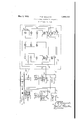
in a diagrammatic manner, for the purpose of illustration, and in no manner in a limiting sense, one form of the invention. In the 'drawingz- The single figure of drawing shows in a wholly diagrammatic manner one form which the invention can assume.
Referring to the drawing, there is shown a stretch of single track constituted by track rails 1, provided with insulating joints 2, for
separating the track into usual insulated signal blocks, L, M and N, there being a source of energy such as a battery 3, connected across the track rails at the exit end of each block,
and a track relay TR, connected across the track rails at the entrance end of each block, the directionof trafiic being as indicated by the arrow.
Since the apparatus employed at the various signal locations is identical, corresponding parts will'be designated by like reference characters, with distinctive exponents for the different signal locations.
At each signal location, at the entrance end to each block, is a wayside signal S. Each way side signal includes 9 light sources, such as incandescent lamps, and in the particular embodiment being described three yellow lamps Y Y and Y three red lamps R R and R and three green lamps G G and G For controlling the lamps of each signal,there are included in each signal in the particular embodiment being described, four relays, two for the green lamp control, 1G and 2G, and two for the yellow lamp control, lY and EZY. Located at each signal location, in addition to the track relay TR, is a home relay HR,a line relay LR and an approach lighting relay ALB.
1n the drawing, a signal S has been shown on an enlarged scale, for facility in describing the invention, but it should be understood that the signal S, and the signal S are identical, in construction and are similarly positioned along the trackway. To simplify the tracing of circuits, and the describing of the invention, a usual convention is followed of employing the letters B and C for designating opposite terminals of a source or sources of electrical energy. As above described, each signal S includes nine separate light sources, three of which are yellow, three of which are green, and three of which are red. The various signal aspects which can be set up by eachsignal S are the following :One, two or three reds indicates stop, asingle yellow indicates slow speed prepared to stop, two yellows indicates medium speed prepared to stop at the next signal, and three yellows indicates normal speed prepared to stop at the next signal. One green indicates slow speed, two greens indicates medium speed, and three greens indicates normal speed.
It is thus seen that it is possible to set up a plurality of distinctive indications giving various speed controls, the indications being more restrictive for yellow than for green, and more restrictive for red than for yellow. The indication is also more restrictive in speed, with two greens than with three, and
that block M is occupied. Relay TR" releases, to thereby de-energize approachlighe ing relay ALR, for the signallocation nextin advance to thus put energy-on signal S through contact fingers, and back point of relay ALR through multiple'circuits through Signal S. By means of the approach lighting relays ALR, a signal S, for anyparticular block, receives energy only upon the occupancy of the immediately preceding block. A first circuitincludes contact finger 4 and backfpointfof relay ALB, wire 5, contact finger 6and back point ofrelay l Y, contact finger? and back point of relay 1G, contact finger 8tand back point of relay 2G, contact finger9-andback point of relay QY, and the three red lamps B R and R in multiple. A second multiple circuit for energy to flow to signal S, includescontactfinger l and back poi-ntof relay ALB, wire 10, conta'ctfinger 11 and front point of relay HR, contact finger 1 2 an dfr0nt point of'relay-LR, wire 13, and then through multiple paths, oneincluding resistance r, lamp G and relay lG,-'and the ogier including lamp G lampG and relay This results in the signal, with block N unoccupied to thus keep and energized) and the block advance unoccupied (to thus keepLR energized), displaying three green lights, designating block N to be a clear block, theredlights not being energized through theredlight circuit traced above, since this circuit is broken by the picking I up of relays 2G and lGiminediately upon energization of the green lamps. If desired, a current retarding means ofany desired'character, such as a resistance, can be placed in the red lamp circuit traced above, whereby to give .the green lamp circuit sufficient advantage over the red lampcircuit to prevent any momentary energization of the red lamps under the existingconditions.
' Assume'for themoment, the occupancy of block Nand non-occupancy o t'block M, then 'r-"elayTR and home relayI-IR are de-energized which results in the de-energizing of line. relay'LR- 'ofthe block immediately to the rear,the home relay HR" of thisv block immediately to the rear remaining up, to thus setxiup caution-conditions for the blockKM) .to the rear of an occupied blockfN). :1
Accordingly, for explainingcaution .condition's, assumeall blocks unoccupied, except the blo'ckimmediately in advance ofblock N, then line relay Llt is. vde-energized, while track relay TR and home relay HR remain energized, whereby on a train entering block M, energy passing through contact 4 and back point of approach lighting relay ALR, which formerly went to the green lights, ,now passes through Wire 10, contact finger 11 and front point of HR, contact finger 12 and back'point of LB, wires 14 and 15,:to then divide and in one case pass through resistance r, lamp Y and relay lY, and in the other case through lamp Y lamp .Y and-relay 2Y. Thus, under caution conditions, signal S normally displays three yell-ow lights.
Under danger conditions, as, for example,
'under occupancy of block N, relay TB is deenergized toin turn de energizejrel-ayfHR,
the gr-een lamps, is interrupted, contact .finger 11- of relay HR being in released position. As a result, the yellowand green relays-LY and 21, and'lG andjQG, are all, de-energized to thereby set up the energizing circuitfor the three red lamps EBB-R and R as traced above. Y
Since, in'thecase of the'yellow and-the green lamps, two of each-are'energized lIlZSB- ries, with this series arrangement connected up i-nmultiple with. the thirdlamp of the same color, it is obvious thattfailure'of the green lamp (3} for example, whenclear conditions prevail,- resultsQin the signal aspect changing from three greens to the above described more restrictive'speed aspect of two greens. Alsofif onev or both of thesgreen lamps G and G should'fail under clear .conditions, the signal :aspect changes from three greens to the still more restrictive speed. aspect of one green, V r i .Since the arrangement 7 in connection with the green lamps and the yellow lamps is identical, a likeoperation takes place iniconnection withtheyellowlai'npa on failureof various of such lamps under ,caution'conditions. If, under cleariconditions, all of the green lamps should become extinguished, the two green relays- QG and 1G would become jde-' energized to thereby transfer energyfrom the green lamps to the yellow lamps through a circuit which includes the green lamp energizingci-rcuit traced above up through wire 13 to the point 16, and from here, energy not being vabletoflow throughthe green lamps, can now flow throughwire-l7, contact finger l8 and back point ofrelay "2G, contact finger 19 and back. point ofrelay.1G,w-ire 20, to wire 15, which is the energizing wire-for the yellow lamps, as described above. I In this manner, upon all of the green lamps being extinguished when they should beilluminated, energyis shifted over from the green lamps, through'back points ofthe green relays, to the yellow lamps, so that theyellow lamps function under clear conditions, inex actly the same manneras if they had been energized through contactlfinger $12 and back ner whatsoever, in a limiting sense.
point of relay LR, due to a change in traflic conditions from clear to caution. Thus, failure of the green lamps results in a signal condition exactly the same as if trafiic conditions had changed to a more restrictive condition.
In a like manner, under caution conditions, when the three yellow lamps should normally be energized, should these lamps all become extinguished, as by filament failures of Y and one or the other or both of lamps Y and Y the yellow relays 2Y and lY are de-energized to thereby complete the energizing circuit for the three red lamps, as described above. It should be remembered that this red lamp energizing circuit passes through contact finger 4 and back point of relay ALR, and then through back points, in series, of the two green relays and the two yellow relays.
From the above it is clear that under normal operating conditions, as traffic conditions in any particular block changes from clear to caution to danger, the wayside signal at the entrance end of such block displays respectively three green lights, three yellow lights, and three red lights.
On any one of the three green lights or of the three yellow lights normally energized at a given time, becoming extinguished, the signal aspect changes to either two lights or one light of the same color, to thereby indicate a more restricted speed.
On failure of all of the green lights under clear conditions, the signal aspect changes automatically to three yellow lights, due to the release of the two green relays, 2G and 16:. In a like manner, on extinguishment of all the yellow lights when they should be illuminated, the signal aspect changes to three red lights, due to the release of the two yellow relays 2Y and 1Y.
With the arrangement of parts as described above, it is therefore clearthat a wayside signal has been provided, showing a large number of distinctive indications of varying restrictiveness for indicating various speeds, with means whereby the indications automatically change to more and more restrictive speed indications according as traffic conditions change and also according as certain of the lamps which should be properly energized at a given time, fail for any reason whatsoever.
The above rather specific description of one form of the invention, is given solely by way of example, and is not intended, in any 11131,;- viously, the invention can assume many different physical forms, and is susceptible of numerous modifications, and it is intended to include, in this application, all such forms and modifications as come within the appended claims.
Having described my invention, I new claim 1. A railway light signal, comprising, a
plurality of proceed, caution, and stop lamps, the proceed and caution lamps being energized, in each case, through multiple circuits, whereby the failure of one proceed or one caution lamp leaves other lamps of its kind energized, and means controlled in accordance with trai'iic for selectively energizing all of the lamps of a like restrictiveness.
2. A railway light signal, comprising, a
plurality of proceed, caution, and stop lamps,
the proceed and caution lamps being energized, in each case, through multiple circuits whereby the failure of one proceed or one caution lamp leaves other lamps of its kind energized, means controlled in accordance with trafilc for selectively energizing all of the lamps of a like restrictiveness, and relay means in series with certain of the proceed and control lamps, whereby failure of all the lamps of a kind, when they should be energized, causes energization of all of the lamps of a kind giving the next more restrictive indication.
3. In a signal system, a stretch of track divided into signalling blocks, a signal at the entrance to each block, each signal including three green, three yellow, and three red lamps, the green and the yellow lamps, in each case, being arranged in groups of two and one lamps each in series with a control relay, and energized in multiple, traffic controlled means for selectively energizing all lights of a kind, the multiple energizing circuits for the yellow lamps including in series, back points of the two green control relays.
i. In a signal system, a stretch of track divided into signalling blocks, a signal at the entrance to each block, each signal including three green, three yellow, and three red lamps,
, the green and the yellow lamps, in each case, 1
being arranged in groups of two and one lamps each in series with a control relay and energized in multiple, traffic controlled means for selectively energizing all lights of a kind,
the multiple energizing circuits for the yellow 73.:
lamps including in series, back points of the two green control relays, and an energizing circuit for energizing the red lamps in multi ple including, in series a back point of each of the two green control relays and the two ."I
yellow control relays.
In testimony whereof I afiix my signature.
FREDERICK B. VVIEG'AND.
Priority Applications (1)
| Application Number | Priority Date | Filing Date | Title |
|---|---|---|---|
| US394222A US1856525A (en) | 1929-09-21 | 1929-09-21 | Light signal system for railroads |
Applications Claiming Priority (1)
| Application Number | Priority Date | Filing Date | Title |
|---|---|---|---|
| US394222A US1856525A (en) | 1929-09-21 | 1929-09-21 | Light signal system for railroads |
Publications (1)
| Publication Number | Publication Date |
|---|---|
| US1856525A true US1856525A (en) | 1932-05-03 |
Family
ID=23558057
Family Applications (1)
| Application Number | Title | Priority Date | Filing Date |
|---|---|---|---|
| US394222A Expired - Lifetime US1856525A (en) | 1929-09-21 | 1929-09-21 | Light signal system for railroads |
Country Status (1)
| Country | Link |
|---|---|
| US (1) | US1856525A (en) |
-
1929
- 1929-09-21 US US394222A patent/US1856525A/en not_active Expired - Lifetime
Similar Documents
| Publication | Publication Date | Title |
|---|---|---|
| US2148005A (en) | Railway signaling | |
| US1856525A (en) | Light signal system for railroads | |
| US1827786A (en) | Electrical signaling | |
| US2697778A (en) | Railway traffic controlling apparatus | |
| US2618740A (en) | Railway signal control system for single track railways | |
| US2107679A (en) | Railway signaling | |
| US2763452A (en) | Two wire-four indication railway signal control system | |
| US2738416A (en) | Light-out protection in a three-block four-indication signaling system | |
| US2241958A (en) | Railway signaling | |
| US2623162A (en) | Railway signal control system | |
| US2268193A (en) | Controlling apparatus for highway crossing signals | |
| US2146054A (en) | Railway signaling system | |
| US1627453A (en) | Control means for light signals | |
| US1864805A (en) | Apparatus for the control of highway crossing signals | |
| US2736794A (en) | Lightout protection for 3-block 4-indication signalling system | |
| US2150292A (en) | Railway signaling | |
| US1720866A (en) | Railway-traffic-controlling apparatus | |
| US2018818A (en) | Railway traffic controlling apparatus | |
| US2237804A (en) | Interlocking control apparatus | |
| US2107680A (en) | Railway signaling | |
| US1295896A (en) | Cab signal system. | |
| US1340500A (en) | ringer | |
| US1785704A (en) | Check-light signal | |
| US2316929A (en) | Railway signaling apparatus | |
| US2124660A (en) | Railway signaling |