US1856521A - Stoker - Google Patents
Stoker Download PDFInfo
- Publication number
- US1856521A US1856521A US404266A US40426629A US1856521A US 1856521 A US1856521 A US 1856521A US 404266 A US404266 A US 404266A US 40426629 A US40426629 A US 40426629A US 1856521 A US1856521 A US 1856521A
- Authority
- US
- United States
- Prior art keywords
- conduit
- fuel
- riser
- curved
- grates
- Prior art date
- Legal status (The legal status is an assumption and is not a legal conclusion. Google has not performed a legal analysis and makes no representation as to the accuracy of the status listed.)
- Expired - Lifetime
Links
- 239000000446 fuel Substances 0.000 description 30
- 230000003137 locomotive effect Effects 0.000 description 16
- 238000010276 construction Methods 0.000 description 4
- 239000002245 particle Substances 0.000 description 2
- OKTJSMMVPCPJKN-UHFFFAOYSA-N Carbon Chemical compound [C] OKTJSMMVPCPJKN-UHFFFAOYSA-N 0.000 description 1
- 229910052799 carbon Inorganic materials 0.000 description 1
- 230000003247 decreasing effect Effects 0.000 description 1
- 230000003116 impacting effect Effects 0.000 description 1
- 238000012856 packing Methods 0.000 description 1
- 239000007787 solid Substances 0.000 description 1
- 235000015096 spirit Nutrition 0.000 description 1
Images
Classifications
-
- F—MECHANICAL ENGINEERING; LIGHTING; HEATING; WEAPONS; BLASTING
- F23—COMBUSTION APPARATUS; COMBUSTION PROCESSES
- F23K—FEEDING FUEL TO COMBUSTION APPARATUS
- F23K3/00—Feeding or distributing of lump or pulverulent fuel to combustion apparatus
- F23K3/04—Feeding or distributing of lump or pulverulent fuel to combustion apparatus for locomotive boiler furnaces
Definitions
- This invention relates to stokers, and more particularly to locomotive stokers.
- One of .the objects of the invention is the provision of a newand improved fuel conduit for locomotive stokers whereby fuel may vbe vtransferred from the tender' to the locomotive and forced upwardly into the Vfirebox thereof lin a loose condition and with the eX- penditure of a minimum amount of power.
- Another object of the invention 1 s the provision of a new and improved fuelconduit having novel means for preventing rotation of thefuel in the delivery end of said con-Y duit.
- a further object of the invention is the provision of a new and improved-riser conduithaving a delivery end that is adapted to cooperate with the distributing meansfor eiiiciently supplying fuel to the back corners ('2'0 of the iirebozr.v f
- a still further object of the invention is the provision ofy a new and improved riser conduit having a circularlower endpwhich graduf ally merges into a form angular in cross-section at its upper end.
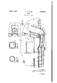
- Fig. 1 is a longitudinal vertical section of a portion of a locomotive tender yand stoker, showing the latter imposition;
- Fig. 2 is a section lon line 2-2 of Fig. 1;
- Fig. 3 is a section on line 3-,3 of Fig. 1;
- Fig'. 4 isa section on line 4 4 of Fig.
- rlhe lpresent invention seeks to overcome these diiiiculties by providing means for preventing packing of the fuel in the delivery end of the conduit, and for preventing the rotation of the mass.
- the reference character 10 designates a locomotive having a fireboX 11 provided with grates 12.
- the backhead 13 is provided with the usual firedoor opening 14 and mudring 15.
- the cab is shown at 16, the deck at 17 and the tender at 18, all of which may be of the usual or any approved construction.
- a suitable conveyor conduit designated generally by the reference character 19 is employed for transferring the fuel from the tender to the locomotive.
- This conduit is adapted to deliver a single stream of fuel through the grates to the iirebox.
- the forward end of the conveyor conduit is curved upwardly and extends through the grates 12 as clearly shown in Fig. 1 of the drawings.
- the conveyor conduit comprises a transfer conduit 21, the forward end of which is preferably curved upwardly as at 22 and is provided with an annular shoulder or seat 23 and a collar or iange 24 for receiving the lower end of the riser or elevator conduit 25 whic is supported by said shoulder.
- the inner surface of the riser conduit is iiush with that of the transfer conduit whereby there is no obstruction to the movement of fuel through said conduits.
- the parts are heldin assembled relation in any suitable manner as by the bolts or screws 26 extending through said collar into the lower end of said riser conduit.
- Fuel transfer means as the screw conveyor 27, is adapted to transferthe fuel Yfrom the tender to the locomotive andfforc'e the same upwardly through the riser conduit in front of the steam nozzle 28 where it is distributed r'over the fireboX.,.,It haspbeen foundb'y ezt-Yl periment that the'screwconveyorvmust. stop short of the forwardiwall of the upwardly curyed portion of the conduit for otherwise the, fuel will bel forced against the vsaidfufallA and become 'packed in the conduit; The'sc'rew conveyor 27 therefore stops short of thefront wall of the .curved portion of the conduit a suflici ent distanceto prevent this pacling,
- the crosssectional.y area of the upper end of the riser conduit 25 has its-forward upperedgepan' allel with the backjwall of the firebox whereby ai better distribution of the fuel'fis insured than where the walls offtheriser conduit are circular, becausear greater portion of the forwardly proj ected Yfuel will be moving sub:-
- the straight side walls will ,deflect les'sof the laterally moving fuel forwardly Vthan the ⁇ curved sidewalls because 75 the laterally moving fuel will strike .
- the straight walls .more nearly normal than it hwould .therear portionsof 'ka curved wall
- tender for said locomotive l a fuelfcond-uit ⁇ forfjtransferring fuel from said tender tofsaidV locomotive delivering the same through said grates into said firebox, comprising a rear portion extending beneath the floor of said tender, a connecting curved portion and a single riser portion extending from said curved portion upwardly through said grates to a point above the level thereof, the forward portion of said conduit gradually changing from circular to substantially equilateral form in cross-section toward its upper end, a helical ,o screw in said conduit for conducting the fuel along the same, and means for distributing the fuel in aerial paths over said grates as the same emerges from said riser conduit.
- a locomotive having a firebox provided with grates, a tender for said locomotive, a fuel conduit for transferring fuel from said tender to said locomotive and delivering the same to a point above the normal firebed in said firebox, said conduit 2o comprising a rear and a forward portion, said rear portion extending beneath said tender and said forward portion comprising a curved portion and a single riser portion, the upper end of said forward portion being substantially equilateral in cross-section and gradually changing to circular form in cross-section from its upper end toward said curved portion, a rotatable screw conveyor in said, rear portion, and a steam distributing nozzle at the rear of the upper end of said riser portion for projecting the fuel delivered by said riser conduit, in aerial paths over the grates of said rebox.
- a locomotive provided with a iirebox having grates therein, a sectional fuel conduit having its rear portion extending beneath the floor of said tender and having its forward portion curved up- Wardly and extending through the grates of said firebox to a point above the normal level of the firebed in said irebox, the forward upper end of said conduit being substantially equilateral in cross-section and gradually decreasing in cross-sectional area and merging into circular form in cross-section toward the curved portion, a rotatable screw in said rear portion and terminating short of the forward wall of the curved portion a suificient distance to prevent impacting of the fuel, and a steam nozzle for projecting the fuel forwardly and laterally in aerial paths over said grates as the same emerges from said conduit.
Landscapes
- Engineering & Computer Science (AREA)
- Chemical & Material Sciences (AREA)
- Combustion & Propulsion (AREA)
- Mechanical Engineering (AREA)
- General Engineering & Computer Science (AREA)
- Solid-Fuel Combustion (AREA)
Description
Patented May 3, 1932 UNITED STATES PATENT OFFICE EDWIN rAIR'JIHER TURNER, 0F NEW YORK, N. Y., ASSIGNOR T0 THE STANDARD STOKER a .COMPANY, INCORPORATED, A CORPORATION F DELAWARE continuation of application Serial No. 194,490, filed May 26, 1927. This application led November 2, 1929.
Serial No.
' This invention relates to stokers, and more particularly to locomotive stokers.
One of .the objects of the invention is the provision of a newand improved fuel conduit for locomotive stokers whereby fuel may vbe vtransferred from the tender' to the locomotive and forced upwardly into the Vfirebox thereof lin a loose condition and with the eX- penditure of a minimum amount of power.
Another object of the invention 1s the provision of a new and improved fuelconduit having novel means for preventing rotation of thefuel in the delivery end of said con-Y duit.
A further object of the invention is the provision of a new and improved-riser conduithaving a delivery end that is adapted to cooperate with the distributing meansfor eiiiciently supplying fuel to the back corners ('2'0 of the iirebozr.v f
A still further object of the invention is the provision ofy a new and improved riser conduit having a circularlower endpwhich graduf ally merges into a form angular in cross-section at its upper end. Other and further'ob'jects and advantages of the invention will appear from the-follow ing description taken in connection with the accompanying drawings, in which Fig. 1 is a longitudinal vertical section of a portion of a locomotive tender yand stoker, showing the latter imposition; Fig. 2 is a section lon line 2-2 of Fig. 1; Fig. 3 is a section on line 3-,3 of Fig. 1;
and
Fig'. 4 isa section on line 4 4 of Fig.
t' In stokers having conveyer conduits terminating in a cylindrical riser conduit through which fuel is forced into the iireboX of the boiler, the fuel will tend to adhere and form a solid mass if the diameter of the riser is substantially that of the conduit, and on emerging from the upper end of the conduit considerable energy is necessarily eX- pended by the distributing jets in breaking up thevmass. Furthermore, the mass will tend to rotate, and the rotation lof the mass, Athe lower fend of which is. curved rearwardly ling of the particles at the curved portion of the riser, thus tending to pulverize the fuel more or less. The friction between the rotating mass and the walls of the conduit will also tend to pulverize the fuel to a certain extent.
yAll this is objectionable because of the' strong drafts employed in locomotives, which tend to carry a great amount of the iiner particles through the stack as unconsumed carbon. p f
rlhe lpresent invention seeks to overcome these diiiiculties by providing means for preventing packing of the fuel in the delivery end of the conduit, and for preventing the rotation of the mass.
Referring now to the drawings, in which similar reference characters designatey the same parts throughout the description, the reference character 10 designates a locomotive having a fireboX 11 provided with grates 12. The backhead 13 is provided with the usual firedoor opening 14 and mudring 15. The cab is shown at 16, the deck at 17 and the tender at 18, all of which may be of the usual or any approved construction. y
Since the parts thus far described are of the conventional form of construction itis not thought necessary to further illustrate or describe the same. d
A suitable conveyor conduit designated generally by the reference character 19 is employed for transferring the fuel from the tender to the locomotive. This conduit is adapted to deliver a single stream of fuel through the grates to the iirebox. The forward end of the conveyor conduit is curved upwardly and extends through the grates 12 as clearly shown in Fig. 1 of the drawings.
The conveyor conduit comprises a transfer conduit 21, the forward end of which is preferably curved upwardly as at 22 and is provided with an annular shoulder or seat 23 and a collar or iange 24 for receiving the lower end of the riser or elevator conduit 25 whic is supported by said shoulder.
The inner surface of the riser conduit is iiush with that of the transfer conduit whereby there is no obstruction to the movement of fuel through said conduits. The parts are heldin assembled relation in any suitable manner as by the bolts or screws 26 extending through said collar into the lower end of said riser conduit.
' 4 Fuel transfer means, as the screw conveyor 27, is adapted to transferthe fuel Yfrom the tender to the locomotive andfforc'e the same upwardly through the riser conduit in front of the steam nozzle 28 where it is distributed r'over the fireboX.,.,It haspbeen foundb'y ezt-Yl periment that the'screwconveyorvmust. stop short of the forwardiwall of the upwardly curyed portion of the conduit for otherwise the, fuel will bel forced against the vsaidfufallA and become 'packed in the conduit; The'sc'rew conveyor 27 therefore stops short of thefront wall of the .curved portion of the conduit a suflici ent distanceto prevent this pacling,
It is .understood that suitable means are employed to protect the riser conduit from the intense heat of the're, as is usual in such constructions. kSince thisl feature constitutes no part of the present inventionit was not thought necessaryto illustrate or describe thesami-ji.'`V y ,Y v, Y
Therotation of the screw'y in forcingthe fuelthroug'h the -riser conduit ten/dsto'cause the fuelmass to rotatein said conduit. Suit-V able means 'are' provided for preventing this rotation. Asshown',the upperiportionofthe riser'conduit changes its form in cross-section from 1tslowerport1on. rflielowerportion 1s Circular, ,while the fup'per portion lis non-cinv cular.y They non-circular portion will prevent the'massfromrotating. j Y. 7 f
'In the form of construction selected to illustrate one embodiment of the invention,
t the upper end ofthe riser conduitis angular incross-section.'l lt is preferably rectangu- 'As shown, thev riser conduit* 25, which is circular in cross-sectionfat its lower end, as
Y indicated at 31 in :F ig. 2,graduall'y merges into av quadrilateral with curved corners or Y connecting portions'as shownat 32- in Fig. 3,
and r,from the quadrilateralwith curved connectingportions into a vsquare in cross-section, as shoWIlulat .33in Fig. 4. i The crosssectional.y area of the upper end of the riser conduit 25 has its-forward upperedgepan' allel with the backjwall of the firebox whereby ai better distribution of the fuel'fis insured than where the walls offtheriser conduit are circular, becausear greater portion of the forwardly proj ected Yfuel will be moving sub:-
stantially normal tosaid wall when it strikes the same, and hence will not be deflected laterally, whereas with a circular wall a great portion of the forwardly projected fuel will strike the curved portions of the side walls and be deflected toward the' center lineof the reboX;
Furthermore, the straight side walls will ,deflect les'sof the laterally moving fuel forwardly Vthan the` curved sidewalls because 75 the laterally moving fuel will strike .the straight walls .more nearly normal than it hwould .therear portionsof 'ka curved wall,
Lwith the 'result that fuel isme'eftcently tion may be made without departing from the spi-rit'and `scope of the appended-claims. I claim as my invention: Y i l. In combination, ka locomotive provided with a firebox havingy grates.,y therein, 'a tender for said locomotive, a fuel conduit having its rear portion extending beneath the ,79,5 floor of `said, tender 'and having-lits forward portion curved upwardly Vvand Vextending through said grates to a pointabove the plane thereof, the upwardly'extending porf tion `of said conduit being substantially circular in cross-section and gradually'increas-r ing in cross-'sectional' area and merging into a substantially Yequi-lateral n .configuration i at its upper end, the lfrontside of: said rectangular portion extending transversely of said fireboX, a helical screwain ysaidfconduit for conductingfuel from-said tenderand delivering it Vinto saidfreboX in a single, continuous stream, andmeans including, ak steam nozzle located at thefrear[offtherectangular portion; lof said conduit 'for vprojecting fuel emerging fromlsaidiconduit in aerialfpaths over the grates insaid trebox..v
2. In Stoker v1nec hanisrnla. continuous, jointed, singleconduit having a curved por@ tion at one Vend, said conduit beingcircular in cross-section adjacent to saidfcurved porion and gradually increasing in Vcross-sec.- tional area and merging into a. substantially equilateral ,configuration toward0 the end'vof l?? its curved` portion, andY a helical screw in the rear portion of said conduitrfor conducting vfuel along the rear Yportion of said conduit `and forcing the same throughsaid curved Portion(Y Y, i 125 3. In' combination, `alocomotivehaving a pfireboxf provided with: grates, a. tender for said locomotive,l a fuelfcond-uit` forfjtransferring fuel from said tender tofsaidV locomotive delivering the same through said grates into said firebox, comprising a rear portion extending beneath the floor of said tender, a connecting curved portion and a single riser portion extending from said curved portion upwardly through said grates to a point above the level thereof, the forward portion of said conduit gradually changing from circular to substantially equilateral form in cross-section toward its upper end, a helical ,o screw in said conduit for conducting the fuel along the same, and means for distributing the fuel in aerial paths over said grates as the same emerges from said riser conduit.
4. In combination, a locomotive having a firebox provided with grates, a tender for said locomotive, a fuel conduit for transferring fuel from said tender to said locomotive and delivering the same to a point above the normal firebed in said firebox, said conduit 2o comprising a rear and a forward portion, said rear portion extending beneath said tender and said forward portion comprising a curved portion and a single riser portion, the upper end of said forward portion being substantially equilateral in cross-section and gradually changing to circular form in cross-section from its upper end toward said curved portion, a rotatable screw conveyor in said, rear portion, and a steam distributing nozzle at the rear of the upper end of said riser portion for projecting the fuel delivered by said riser conduit, in aerial paths over the grates of said rebox.
5. In combination, a locomotive provided with a iirebox having grates therein, a sectional fuel conduit having its rear portion extending beneath the floor of said tender and having its forward portion curved up- Wardly and extending through the grates of said firebox to a point above the normal level of the firebed in said irebox, the forward upper end of said conduit being substantially equilateral in cross-section and gradually decreasing in cross-sectional area and merging into circular form in cross-section toward the curved portion, a rotatable screw in said rear portion and terminating short of the forward wall of the curved portion a suificient distance to prevent impacting of the fuel, and a steam nozzle for projecting the fuel forwardly and laterally in aerial paths over said grates as the same emerges from said conduit.
In testimony whereof I affix my signature.
EDWIN ARCHER TURNER.
Priority Applications (1)
| Application Number | Priority Date | Filing Date | Title |
|---|---|---|---|
| US404266A US1856521A (en) | 1929-11-02 | 1929-11-02 | Stoker |
Applications Claiming Priority (1)
| Application Number | Priority Date | Filing Date | Title |
|---|---|---|---|
| US404266A US1856521A (en) | 1929-11-02 | 1929-11-02 | Stoker |
Publications (1)
| Publication Number | Publication Date |
|---|---|
| US1856521A true US1856521A (en) | 1932-05-03 |
Family
ID=23598895
Family Applications (1)
| Application Number | Title | Priority Date | Filing Date |
|---|---|---|---|
| US404266A Expired - Lifetime US1856521A (en) | 1929-11-02 | 1929-11-02 | Stoker |
Country Status (1)
| Country | Link |
|---|---|
| US (1) | US1856521A (en) |
-
1929
- 1929-11-02 US US404266A patent/US1856521A/en not_active Expired - Lifetime
Similar Documents
| Publication | Publication Date | Title |
|---|---|---|
| US1856521A (en) | Stoker | |
| US1213821A (en) | Pulverized-fuel burner. | |
| US1948812A (en) | Locomotive stoker | |
| US1391744A (en) | Fuel-distributer | |
| US745247A (en) | Automatic stoker. | |
| US2119941A (en) | Stoker | |
| US2177794A (en) | Locomotive stoker | |
| US1892353A (en) | Stoker | |
| US2137844A (en) | Blast feed stoker | |
| US1948686A (en) | Stoker mechanism | |
| US1963358A (en) | Combustion furnace | |
| US1946044A (en) | Locomotive stoker | |
| US1671331A (en) | Locomotive stoker | |
| US2302412A (en) | Center delivery stoker | |
| US1814648A (en) | Stoker conveyer | |
| US1796849A (en) | Locomotive stoker | |
| US1760221A (en) | Locomotive stoker | |
| US1851637A (en) | Locomotive stoker | |
| US1984025A (en) | Stoker fuel distributing apparatus | |
| US1892372A (en) | Locomotive | |
| US1797871A (en) | Locomotive stoker | |
| US1324081A (en) | Apparatus for using powdered fuel. | |
| US2297134A (en) | Stoker mechanism | |
| US1195533A (en) | Street | |
| US1717989A (en) | Locomotive stoker |