US185652A - Improvement in machines for making spikes - Google Patents
Improvement in machines for making spikes Download PDFInfo
- Publication number
- US185652A US185652A US185652DA US185652A US 185652 A US185652 A US 185652A US 185652D A US185652D A US 185652DA US 185652 A US185652 A US 185652A
- Authority
- US
- United States
- Prior art keywords
- rings
- roll
- machines
- rolls
- improvement
- Prior art date
- Legal status (The legal status is an assumption and is not a legal conclusion. Google has not performed a legal analysis and makes no representation as to the accuracy of the status listed.)
- Expired - Lifetime
Links
- 230000000875 corresponding Effects 0.000 description 8
- 239000002184 metal Substances 0.000 description 6
- 238000010276 construction Methods 0.000 description 4
- 210000000282 Nails Anatomy 0.000 description 2
- 238000004519 manufacturing process Methods 0.000 description 2
- 230000001105 regulatory Effects 0.000 description 2
- 230000000717 retained Effects 0.000 description 2
Images
Classifications
-
- B—PERFORMING OPERATIONS; TRANSPORTING
- B21—MECHANICAL METAL-WORKING WITHOUT ESSENTIALLY REMOVING MATERIAL; PUNCHING METAL
- B21B—ROLLING OF METAL
- B21B1/00—Metal-rolling methods or mills for making semi-finished products of solid or profiled cross-section; Sequence of operations in milling trains; Layout of rolling-mill plant, e.g. grouping of stands; Succession of passes or of sectional pass alternations
- B21B1/16—Metal-rolling methods or mills for making semi-finished products of solid or profiled cross-section; Sequence of operations in milling trains; Layout of rolling-mill plant, e.g. grouping of stands; Succession of passes or of sectional pass alternations for rolling wire rods, bars, merchant bars, rounds wire or material of like small cross-section
- B21B1/163—Rolling or cold-forming of concrete reinforcement bars or wire ; Rolls therefor
Definitions
- the object of my invention is to produce a machine simple in its parts, and that will accomplish the desired result with certainty.
- two rolls are used. These rolls rotate in opposite directions, and are provided upon their periphery with the necessary dies, placed at suitable distances apart to form the head or body and point of each spike and as the metal of each spike is greatly compressed where the point is formed, it is important that the metal should be supported upon each side of the spike to keep it from spreading.
- My invention consists in .fifoviding the desired support by means of two rings, having internal gears, to be connected with one of the-forming-rolls by means of corresponding external gears formed upon said roll, so that they will rotate with it without slipping.
- My invention consists, also, in giving to the portion of the forming-roll and supportingrings coming in contact or in gear with the other a beveled or conical form, so that the supporting-rings will have a tendency to diverge one from the other.
- My invention consists, also, in providing for the side rings adjustable chilled blocks, connected with the frame to support the rings during the operation, as will be described hereafter.
- F represents the frame of the machine. It is made, preferably, in one piece, to add to the rigidity of its construction.
- a and B are two rolls, mounted upon shafts a and b, passing through bearings that can be regulated as to their distance apart by means of the adjusting-screws 0.
- a gear-wheel, d that mesh-es with a gear-wheel, e, placed upon the shaft b, and thus the rolls A and B are rotated at the same speed, but in opposite directions.
- Each roll is formed with a ridge, a or b, projecting from its circumference, and of the same width as the spike it is intended to form.
- each ring 0 is beveled ofl", conical or sphero-conical, with the smallest opening outward, and the roll B is formed in a nearly corresponding manner, beveled off from the central ridge b, so that each ring 0 will have a tendency to separate from the roll; but as it is desired to support the metal of the spike sidewise while it is passing between the forming-rolls A and B, the rings 0 are kept in contact with the ridges a and b by chilled blocks h, mounted upon bearings f, attached to the vertical sides of the frame F.
- the blocks h can be adjusted in relation to the rings 0 by set-screws g and retaining-screws 9, so as to compensate for any wear of the parts.
- the lower portion of the rings is kept from spreading too far apart by the stationary grooved block F attached to the frame of the machine.
- the location of the rolls may be reversed and the rings 0 and roll B be placed above the corresponding roll A.
- the gears formed within the rings (3 and upon the roll B, may, in some cases, be dispensed with, and fricti n of the parts only be used, the blocks It being replaced by friction-rollers, but I found by experience that one of the rings is liable to slip more than the other and produce spikes that are slightly bent.
- the machine can be used for making horseshoe blanks, nails, bolts. screw-banks, &c.
- the forming-roll B beveled ofi, in combination with the rings 0, having conical interior, in virtue of which said rings diverge from the forming-roll unless retained in the manner substantially as described.
- the adjustable chilled blocks h In combination with the forming-rolls A B, rings 0, and the frame of a machine for making spikes, the adjustable chilled blocks h, to support said rings, substantially as and for the purpose set forth.
Description
J. H. SWETT.
MACHINE FOR MAKING SPIKES, &c.
Patented Dec. 26,1876.
UNITED STATES PATENT QFFIOE.
JAMES H. SWETT, OF PITTSBURG, PENNSYLVANIA.
IMPROVEMENT IN MACHINES FOR MAKING SPIKES, &c.
Specification forming part of Letters Patent No. 185,652, dated December 26, 1876; application filed November 9, 1876.
To all whom it may concern:
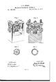
Be it known that I, JAMES H. SWETT, of Pittsburg, in the county of Allegheny and State of Pennsylvania, have invented certain new and useful Improvements in Machines for Making Spikes, &c.; and that the following is a full, clear, and exact description of the construction and operation of the same, reference being had to the accompanying drawing, forming a part of this specification, in which- Figure 1 represents the improved machine in perspective. Fig. 2 represents the same in longitudinal vertical section. Fig. 3 represents an end view of the lower roll. Fig. 4
represents a side View of one of the rings used to operate in connection with the formingrolls.
Similar letters of reference denote like parts in all the figures.
In making spikes with machines, one of the difficulties to be guarded against is the production of a fin at the sides near the point, or to prevent the point being wider than the spike. Many expensive and complicated machines have been made to operate with partial success in view of overcoming this defect.
The object of my invention is to produce a machine simple in its parts, and that will accomplish the desired result with certainty. For this purpose two rolls are used. These rolls rotate in opposite directions, and are provided upon their periphery with the necessary dies, placed at suitable distances apart to form the head or body and point of each spike and as the metal of each spike is greatly compressed where the point is formed, it is important that the metal should be supported upon each side of the spike to keep it from spreading.
My invention consists in .fifoviding the desired support by means of two rings, having internal gears, to be connected with one of the-forming-rolls by means of corresponding external gears formed upon said roll, so that they will rotate with it without slipping.
My invention consists, also, in giving to the portion of the forming-roll and supportingrings coming in contact or in gear with the other a beveled or conical form, so that the supporting-rings will have a tendency to diverge one from the other.
My invention consists, also, in providing for the side rings adjustable chilled blocks, connected with the frame to support the rings during the operation, as will be described hereafter.
In the drawing, F represents the frame of the machine. It is made, preferably, in one piece, to add to the rigidity of its construction. A and B are two rolls, mounted upon shafts a and b, passing through bearings that can be regulated as to their distance apart by means of the adjusting-screws 0. Upon the end of the shaft or is mounted a gear-wheel, d, that mesh-es with a gear-wheel, e, placed upon the shaft b, and thus the rolls A and B are rotated at the same speed, but in opposite directions. Each roll is formed with a ridge, a or b, projecting from its circumference, and of the same width as the spike it is intended to form. Projecting from said ridge, and at regular distances apart, are dies a and b, so placed and beveled upon one roll in relation to the other, as to form the point of each spike and separate one from the other. On each side of the ridge b is placed upon the roll B an internal geared ring, (1, that meshes with a corresponding external gear, b formed on or attached to the roll B. The interior face of either ring 0 is beveled ofl", conical or sphero-conical, with the smallest opening outward, and the roll B is formed in a nearly corresponding manner, beveled off from the central ridge b, so that each ring 0 will have a tendency to separate from the roll; but as it is desired to support the metal of the spike sidewise while it is passing between the forming-rolls A and B, the rings 0 are kept in contact with the ridges a and b by chilled blocks h, mounted upon bearings f, attached to the vertical sides of the frame F. The blocks h can be adjusted in relation to the rings 0 by set-screws g and retaining-screws 9, so as to compensate for any wear of the parts. The
lower portion of the rings is kept from spreading too far apart by the stationary grooved block F attached to the frame of the machine. In this manner I secure a free opening for the admission of every new spike-rod, a positive and long bearing for the sides of the spike while it is formed between the rolls, and a free delivery on the rear of the machine. If desired, the location of the rolls may be reversed and the rings 0 and roll B be placed above the corresponding roll A. The gears formed within the rings (3 and upon the roll B, may, in some cases, be dispensed with, and fricti n of the parts only be used, the blocks It being replaced by friction-rollers, but I found by experience that one of the rings is liable to slip more than the other and produce spikes that are slightly bent. By changing the dies of the forming-rolls and the interior face of the rings 0, the machine can be used for making horseshoe blanks, nails, bolts. screw-banks, &c.
Having thus fully described my invention, what I claim is- 1. In combination with the forming-rolls of a machine for making spikes, &c., and the gears attached or formed upon each side of one of said rolls, the rings 0, provided with internal gears, substantially as and for the purpose described.
2. The forming-roll B, beveled ofi, in combination with the rings 0, having conical interior, in virtue of which said rings diverge from the forming-roll unless retained in the manner substantially as described.
3. In combination with the forming-rolls A B, rings 0, and the frame of a machine for making spikes, the adjustable chilled blocks h, to support said rings, substantially as and for the purpose set forth.
J AMES H. SWETT. Witnesses:
E. E. MASSON, W. R. EDELEN.
Publications (1)
| Publication Number | Publication Date |
|---|---|
| US185652A true US185652A (en) | 1876-12-26 |
Family
ID=2255058
Family Applications (1)
| Application Number | Title | Priority Date | Filing Date |
|---|---|---|---|
| US185652D Expired - Lifetime US185652A (en) | Improvement in machines for making spikes |
Country Status (1)
| Country | Link |
|---|---|
| US (1) | US185652A (en) |
-
0
- US US185652D patent/US185652A/en not_active Expired - Lifetime
Similar Documents
| Publication | Publication Date | Title |
|---|---|---|
| US242058A (en) | sohtjrmann | |
| US185652A (en) | Improvement in machines for making spikes | |
| US775572A (en) | Tool for finishing flanged pipe. | |
| US425951A (en) | Fourth to william w | |
| US384422A (en) | Nail-machine | |
| US69734A (en) | Improved machine for making nails for horseshoes | |
| US358628A (en) | Die for making rolled forcings | |
| US335910A (en) | foulks | |
| US502280A (en) | cramer | |
| US150085A (en) | Jacob russell | |
| US331230A (en) | Machine for rolling flat and nut bars | |
| US151323A (en) | Improvement in mandrels for rolling metal tubes | |
| US1201582A (en) | Apparatus for manufacturing screw-nails and the like. | |
| US699147A (en) | Roll. | |
| US90933A (en) | Improved rolling-apparatus | |
| US118848A (en) | Improvement in the manufacture of plow landsides | |
| US397460A (en) | Hiram emery fuller | |
| US393788A (en) | Leather-rounding machine | |
| US255958A (en) | Rolling-mill for tapering spring-points | |
| US149066A (en) | Improvement in machines for rolling puddlers balls | |
| US353270A (en) | Rolling-mill | |
| US137009A (en) | Improvement in the manufacture of bolts and rivets | |
| US654468A (en) | Spinning-ring. | |
| US200603A (en) | Improvement in machines for rolling blanks | |
| US142945A (en) | Improvement in machines for corrugating and beading sheet-metal pipe |