US1856517A - Method of forming composite piles - Google Patents
Method of forming composite piles Download PDFInfo
- Publication number
- US1856517A US1856517A US312753A US31275328A US1856517A US 1856517 A US1856517 A US 1856517A US 312753 A US312753 A US 312753A US 31275328 A US31275328 A US 31275328A US 1856517 A US1856517 A US 1856517A
- Authority
- US
- United States
- Prior art keywords
- shell
- pile
- section
- concrete
- ring
- Prior art date
- Legal status (The legal status is an assumption and is not a legal conclusion. Google has not performed a legal analysis and makes no representation as to the accuracy of the status listed.)
- Expired - Lifetime
Links
- 238000000034 method Methods 0.000 title description 13
- 239000002131 composite material Substances 0.000 title description 9
- 239000004567 concrete Substances 0.000 description 11
- 239000002184 metal Substances 0.000 description 4
- 239000000463 material Substances 0.000 description 3
- 239000011150 reinforced concrete Substances 0.000 description 2
- 229910000831 Steel Inorganic materials 0.000 description 1
- 238000013459 approach Methods 0.000 description 1
- UQMRAFJOBWOFNS-UHFFFAOYSA-N butyl 2-(2,4-dichlorophenoxy)acetate Chemical compound CCCCOC(=O)COC1=CC=C(Cl)C=C1Cl UQMRAFJOBWOFNS-UHFFFAOYSA-N 0.000 description 1
- 238000010276 construction Methods 0.000 description 1
- 230000000694 effects Effects 0.000 description 1
- 239000000835 fiber Substances 0.000 description 1
- 238000011065 in-situ storage Methods 0.000 description 1
- MYWUZJCMWCOHBA-VIFPVBQESA-N methamphetamine Chemical compound CN[C@@H](C)CC1=CC=CC=C1 MYWUZJCMWCOHBA-VIFPVBQESA-N 0.000 description 1
- 239000002689 soil Substances 0.000 description 1
- 239000010959 steel Substances 0.000 description 1
- 239000002699 waste material Substances 0.000 description 1
- 239000002023 wood Substances 0.000 description 1
Images
Classifications
-
- E—FIXED CONSTRUCTIONS
- E02—HYDRAULIC ENGINEERING; FOUNDATIONS; SOIL SHIFTING
- E02D—FOUNDATIONS; EXCAVATIONS; EMBANKMENTS; UNDERGROUND OR UNDERWATER STRUCTURES
- E02D5/00—Bulkheads, piles, or other structural elements specially adapted to foundation engineering
- E02D5/22—Piles
- E02D5/48—Piles varying in construction along their length, i.e. along the body between head and shoe, e.g. made of different materials along their length
Definitions
- FIG. 5 is a diagrammatic representation of FIG. 5.
- This invention pertains to composite piles formed by first driving a lower pile section below ground level and then completing the pile by forming on top of the lower section 5 an upper section of concrete in order to bring the top of the finished pile to the desired height.
- the apparatus is so arranged that each blow of the hammer is applied to both the pile and the shell with the result that the shell is pushed into the ground along with the pileand is ready to serve as a mold for concrete as soon as the follower is withdrawn.
- Another known method is to drive the lower pile section to proper depth within a casing, then attachan upwardly projecting shell to the top of the lower pile, then fill the shell with concrete to the proper level, and then withdraw the casing.
- the shell be driven by blows on its upper end, the shell may be a lain cylinder, which is an economical shape,
- the shell be driven by blows imparted to its wall, the shell must be tapered outwardly toward the top, or must be corrugated or otherwise shaped to engage the follower. Both these expedients use considerable excess .metal as compared to the plain cylindrical shell.
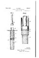
- FIG. 1 shows a completed pile before the upper end of the shell has been removed
- the principal resistance to I be'overcome by the shell is the skin friction of the 'earth'on the shell. This resistance may be reduced if desired by forming the upper portion of shell 24 in conical form as indi-- cated in Fig, 1,
- r theshell is drawn into the ground by virtue of its attachmentto theh ead of the lower pile section.
- the shell is caused to follow thefpileginto'the ground by tensionapp to its lower end, but without fastening 1 the shell to the pile;
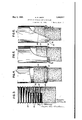
- the lower pile section I as 32 is provided at its uper end with a tenonlike portion 34.
- Encircling tenon 34; is a Figs. 3 tot), inclusive, show various methsteel ring 36 to which is riveted the lower end of cylindrical steel shell 38.
- the shell 40 is corrugated with plain circumferential corrugations, not screw threaded.
- the head 42 of the lower pile section is corrugated to correspond to the shell.
- To apply theshell to the pile the shell is slit as at 44, the slit end is forced over :pile'head 423116. then held in place by wires e6 wrapped around the shell in the corrugations thereof.
- Fig. fillustrates an arrangement in which the lower end'of the shell 50 is provided with an internal ring 52, just as in Fig. 2 ring 38 has a ring 36.
- the pile head 54 is enlarged and ring 52 is underneath the head so that ring and shellare drawn-intothe earth with the pile.
- 'NVhen'this scheme is used the shell and ring are slipped onto the pile from the lower endbefore drivingis begun.
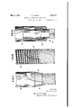
- the wooden ring may readily beformed in sections and simply nailed to the shell; therefore it may be applied after.
- the lower pile section is partly drive-n.-
- Ring "64" is placed under pile head 64 and shell 6() is attached thereto by nails'66.
- Fig. 5 the lower end of shell 70 is'slipped down past "enlarged pile head 72, crimped as at 7 4 underneath the rim of head 72 andthen bound withwires 76.
- the metal ofthe shell is so thin that thec-rimping may readily be done with a hammer.
- Fig. 7 shows a-scheme in which shell 80 is provided at its lower end with aconical .por'- tion 82 of reduced diameter which surrounds a corresponding conical head 842011 the pile.
- w 7 Fig. 6 is "similar to Fig. 4 except that shell 60 is provided with awooden ring 62 instead The shell is slipped over' the bottom end of the pile section before driving begins.
- a corrugated shell such as 90 (Fig.8) may be used to'a'dvant'age. This shell is screw threaded throughout its length and the'low'er end is screwed onto the threaded head 92of the lower pile 'section'just as in Fig. 1. The lower end of shell'24is screwed to pile head 22.
- the shells illustrated and described above are all of circular cross section but it will be understood that they may be of square, rectangular, or any other desired shape.
- a method of forming a composite pile which comprises driving the lower section until its upper end approaches ground level, attaching an upwardly extending shell to said upper end, inserting a follower through said shell into contact with said upper end, driving said lower section below ground level by means of said follower, whereby said shell is drawn into the ground by virtue of its attachment to said lower section, and filling said shell with concrete to form the upper pile section.
Landscapes
- Engineering & Computer Science (AREA)
- Structural Engineering (AREA)
- Life Sciences & Earth Sciences (AREA)
- General Life Sciences & Earth Sciences (AREA)
- Mining & Mineral Resources (AREA)
- Paleontology (AREA)
- Civil Engineering (AREA)
- General Engineering & Computer Science (AREA)
- Placing Or Removing Of Piles Or Sheet Piles, Or Accessories Thereof (AREA)
- Piles And Underground Anchors (AREA)
Description
H. R. SMITH METHOD OF FORMING COMPOSITE FILES Filed Oct. 16, 1928 3 Sheets-Sheet FIG. 2.
May 3, 1932.
May 3, 1932.
FEES.
FIG. 5.
H. R. SMITH METHOD OF FORMING COMPOSITE PILES Filed Oct. 16, 1928 3 Sheets-Sheet 2 FIGA.
FIG. 3.
I anomb'oz NR SWLcA May 3, 19 32. H. R. SMITH 1,856,517
METHOD OF FORMING COMPOSITE FILES Filed Oct. 16, 1928 3 Sheets-Sheet 3 FIG. 9.
g A gvwqntoz 33513 M a pha/4013 WWW I In the above practice, after the Patented May 3, 1932 UNITED STATES PATENT OFFICE HERMAN IR. SMITH, OF DOUGLASTON, NEW YORK, ASSIGNOR TO RAYMOND CONCRETE IPILE COMPANY, OF NEW YORK, N. Y., A CORPORATION OF NEW JERSEY METHOD OF FORMING COMPOSITE PILES Application filed October 16, 1928. Serial No. 312,758.
This invention pertains to composite piles formed by first driving a lower pile section below ground level and then completing the pile by forming on top of the lower section 5 an upper section of concrete in order to bring the top of the finished pile to the desired height.
One of the greatest problems of the pile driving industry arises from the fact that it is impossible to know just how long each pile should be before driving it.
If, after a pile has been driven, it is found to be too long, the top of the pile must be out off. This is an easy operation when the 16 pile is of wood but is a dificult and very expensive operation when the pile is composed of reinforced concrete.
To avoid the great waste of material and labor incident to the cutting olf and throw- 20 ing away of the tops of concrete piles, the practice has been developed of first driving a pile which is known to be too short, and
then piecingit'out by forming on the upper end thereof a concrete upper section cast in situ and with its top at the proper level. Such a structure, when finished, is known as a composite pile. The present invention has to do with the method of forming the upper section of a'pile of that kind.
Under some conditions and soils it is feasible to simply drive the lower section to desireddepth with its upper end below ground level, and then fill with concrete the hole in the ground above the lower section, the surrounding earth acting as the wall of the mold. Under other conditions thelower section is driven as above and the earth around its upper end is excavated to permit setting up a mold in which the upper concrete pile section is formed. 1
I with concrete to the desired level, and finally to cut olf the pieces of empty shellprojecting above that level.
shell is The usual practice, however, is to first drive I reaches the proper depth, then fill the shell placed on the lower pile section, the subsequent driving of the pile is usually done by means of a follower lowered through the shell to act on the head of the pile section, the
driving effect of the hammer acting through the follower on the upper end of the pile and also on the wall or the upper end of the shell.
The apparatus is so arranged that each blow of the hammer is applied to both the pile and the shell with the result that the shell is pushed into the ground along with the pileand is ready to serve as a mold for concrete as soon as the follower is withdrawn.
Another known method is to drive the lower pile section to proper depth within a casing, then attachan upwardly projecting shell to the top of the lower pile, then fill the shell with concrete to the proper level, and then withdraw the casing.
All the above methods are objectionable on account of cost. If the shell be driven by blows on its upper end, the shell may be a lain cylinder, which is an economical shape,
ut in order to provide sufficient rigidity it must be of excessive thickness, and therefore expensive.
If the shell be driven by blows imparted to its wall, the shell must be tapered outwardly toward the top, or must be corrugated or otherwise shaped to engage the follower. Both these expedients use considerable excess .metal as compared to the plain cylindrical shell.
In the above mentioned scheme of forming the pile within a casing, a plain shell may be used, but the method is objectionable on account of high cost of labor and overhead. 1
All of the above Objections are overcome by the present invention, which discloses the method of drawing the shell into the ground by tension applied at the lower end of the shell. This method permits the use of a plain cylindrical or inwardly tapered shell of very thin material, consequently the method has, under, certain conditions, considerably cut the cost of forming composite piles.
In the drawings, which show what I now consider to be the preferred form of the invention:
threaded upper end 22'andthe lower end of Fig. 1 shows a completed pile before the upper end of the shell has been removed, and
also shows the follower which was used to is pulled into the ground by tension applied shell 24 was threaded as at 26 to correspond.
T he lower section was driven in the ordinary manner'until the threaded head was near ground level. Then'the shell was attached to y the pile'section by screwing the threaded portion onto pile head 22. Follower 28 was then lowered through the shell to rest on thetop of the precast pile'section and the driving operation was resumed As the pile was forcedinto the ground, the shell, being fast to the pile, was pulled down by tension to the position shown in the drawings. Then the follower was removed and'the shell was filled with concrete 30 to ground level. The job willbe complete when the empty upper end of shell 24 is cut off by an axe or other common tool. For clarity of illustrat on the shells are shown in thedrawings as having considerable thickness, but i'n reality they are very thin. Usually they are of metal but may be of paper, fiber, or other suitable sheet material. This .is possible because the shell at its lower end, instead of being pushed down from above as in previous practice. I
' While the shell is being drawn into the ground by the pile, the principal resistance to I be'overcome by the shell is the skin friction of the 'earth'on the shell. This resistance may be reduced if desired by forming the upper portion of shell 24 in conical form as indi-- cated in Fig, 1,
1 driving. In thisparticular the present meth 'od has an important advantage over previous qpractic e on account ofthe light weight of the thin shell as compared withithe thick' Files, are usually driven 'byblows of a hammer. The pile, comes to rest between blows. therefore the inertia of the driven mass has considerable bearing on the, ease of shells heretofore used.
In all figuresof the drawings except Fig. 2,
r theshell is drawn into the ground by virtue of its attachmentto theh ead of the lower pile section. In Fig.2 the shell is caused to follow thefpileginto'the ground by tensionapp to its lower end, but without fastening 1 the shell to the pile; The lower pile section I as 32 is provided at its uper end with a tenonlike portion 34. Encircling tenon 34; is a Figs. 3 tot), inclusive, show various methsteel ring 36 to which is riveted the lower end of cylindrical steel shell 38. The bottom surface of follower 28 extends over tenon 34 and ring 36, therefore a part of each blow on the follower is imparted to :the ring, with the result that the shell is drawn into-the earth as effectively as if the shell were attached to the pile itself. a v a Figs. .3. to '9 inclusive show variousscheme's for fastening'theshell tothepilerI-n Fig. 3
the shell 40 is corrugated with plain circumferential corrugations, not screw threaded. The head 42 of the lower pile section is corrugated to correspond to the shell. To apply theshell to the pile the shell is slit as at 44, the slit end is forced over :pile'head 423116. then held in place by wires e6 wrapped around the shell in the corrugations thereof.
Fig. fillustrates an arrangement in which the lower end'of the shell 50 is provided with an internal ring 52, just as in Fig. 2 ring 38 has a ring 36. In Fig; 4, however, the pile head 54 is enlarged and ring 52 is underneath the head so that ring and shellare drawn-intothe earth with the pile. 'NVhen'this scheme is used the shell and ring are slipped onto the pile from the lower endbefore drivingis begun.
of a metal ring 52. The wooden ring may readily beformed in sections and simply nailed to the shell; therefore it may be applied after. the lower pile section is partly drive-n.-
Ring "64" is placed under pile head 64 and shell 6() is attached thereto by nails'66.
' In Fig. 5 the lower end of shell 70 is'slipped down past "enlarged pile head 72, crimped as at 7 4 underneath the rim of head 72 andthen bound withwires 76. The metal ofthe shell is so thin that thec-rimping may readily be done with a hammer.
Fig. 7 shows a-scheme in which shell 80 is provided at its lower end with aconical .por'- tion 82 of reduced diameter which surrounds a corresponding conical head 842011 the pile.
w 7 Fig. 6 is "similar to Fig. 4 except that shell 60 is provided with awooden ring 62 instead The shell is slipped over' the bottom end of the pile section before driving begins.
Under certain conditionsthe pressure of the ground through whichthe shell is; drawn is suflicient to collapse a plain shell. To meet such circumstances a corrugated shell such as 90 (Fig.8) may be used to'a'dvant'age. This shell is screw threaded throughout its length and the'low'er end is screwed onto the threaded head 92of the lower pile 'section'just as in Fig. 1. The lower end of shell'24is screwed to pile head 22. The corrugatedshell in Fig.
tions.
. In 9 -t h'e pla'in'shell 1001s provided-with a lower-screw threaded'portion'102'which is 3 is also suitable for use under these conch-"- screwed onto a reinforced concrete collar 104 attached'nearthe upper-enact wo'od'pile 106, as 1s fullyset forth in thecopen ding applica tion of Elihu Watt, Serial No. 292,838, filed July 14:, 1928.
The shells illustrated and described above are all of circular cross section but it will be understood that they may be of square, rectangular, or any other desired shape.
It is to be understood that the invention is not limited to the construction herein specifically illustrated and'described but may be embodied in other forms Without departure from its spirit as'defined by the appended claims.
I claim- 1. A method of forming a composite pile which comprises driving the lower section until its upper end approaches ground level, attaching an upwardly extending shell to said upper end, inserting a follower through said shell into contact with said upper end, driving said lower section below ground level by means of said follower, whereby said shell is drawn into the ground by virtue of its attachment to said lower section, and filling said shell with concrete to form the upper pile section.
2. The method of forming a composite pile which comprises driving a pile section below surface level and pulling downwardly with said pile section, a shell by force applied solely to the pile section.
In testimony whereof I hereto affix my signature. 7
HERMAN B. SMITH.
Priority Applications (1)
| Application Number | Priority Date | Filing Date | Title |
|---|---|---|---|
| US312753A US1856517A (en) | 1928-10-16 | 1928-10-16 | Method of forming composite piles |
Applications Claiming Priority (1)
| Application Number | Priority Date | Filing Date | Title |
|---|---|---|---|
| US312753A US1856517A (en) | 1928-10-16 | 1928-10-16 | Method of forming composite piles |
Publications (1)
| Publication Number | Publication Date |
|---|---|
| US1856517A true US1856517A (en) | 1932-05-03 |
Family
ID=23212856
Family Applications (1)
| Application Number | Title | Priority Date | Filing Date |
|---|---|---|---|
| US312753A Expired - Lifetime US1856517A (en) | 1928-10-16 | 1928-10-16 | Method of forming composite piles |
Country Status (1)
| Country | Link |
|---|---|
| US (1) | US1856517A (en) |
Cited By (2)
| Publication number | Priority date | Publication date | Assignee | Title |
|---|---|---|---|---|
| US5486071A (en) * | 1992-02-19 | 1996-01-23 | Roger Bullivant Of Texas, Inc. | Method and apparatus for supporting a load |
| US10822762B2 (en) * | 2017-06-12 | 2020-11-03 | Ppi Engineering & Construction Services, Llc | Combination pier |
-
1928
- 1928-10-16 US US312753A patent/US1856517A/en not_active Expired - Lifetime
Cited By (2)
| Publication number | Priority date | Publication date | Assignee | Title |
|---|---|---|---|---|
| US5486071A (en) * | 1992-02-19 | 1996-01-23 | Roger Bullivant Of Texas, Inc. | Method and apparatus for supporting a load |
| US10822762B2 (en) * | 2017-06-12 | 2020-11-03 | Ppi Engineering & Construction Services, Llc | Combination pier |
Similar Documents
| Publication | Publication Date | Title |
|---|---|---|
| US5833399A (en) | Apparatus for use in forming piles | |
| US1954070A (en) | Pile | |
| US7726913B1 (en) | Method and apparatus for forming in ground piles | |
| US4009582A (en) | Method for forming deep cast-in-place caseless concrete piles | |
| US3925998A (en) | Method for forming cast-in-place caseless concrete piles | |
| US1856517A (en) | Method of forming composite piles | |
| US1865652A (en) | Method and apparatus for placing concrete in piles | |
| US2326872A (en) | Apparatus for forming cast-in-place concrete piles | |
| US3316722A (en) | Pile driving mandrel construction and method | |
| US4725167A (en) | Pile driving | |
| US1805265A (en) | Screw conveyer pile | |
| CN109680681A (en) | A kind of pile crown restructuring bankrupt of cast-in-situ bored pile | |
| RU2426835C1 (en) | Device to form bore piles | |
| GB2129856A (en) | A method of and an apparatus for producing in-situ concrete piles with enlarged bases | |
| GB2070668A (en) | Auger for the manufacturing of concrete foundation piles | |
| US2684576A (en) | Method and device of forming piles molded in the ground by filling thin sheathings | |
| US2200524A (en) | H-beam composite pile | |
| US2912829A (en) | Composite piles and joiners therefor | |
| GB2064625A (en) | Method of Hole Forming for Miniature Piles | |
| US1449032A (en) | Concrete pile and method of forming same | |
| GB2132667A (en) | Method of installing precast concrete piles | |
| US3090204A (en) | Method of forming concrete shell in ground | |
| US3279196A (en) | Pile construction | |
| US2021735A (en) | Concrete pile | |
| US1236556A (en) | Hollow core for use in making concrete piles. |