US1856516A - Gas reversing valve - Google Patents
Gas reversing valve Download PDFInfo
- Publication number
- US1856516A US1856516A US45504730A US1856516A US 1856516 A US1856516 A US 1856516A US 45504730 A US45504730 A US 45504730A US 1856516 A US1856516 A US 1856516A
- Authority
- US
- United States
- Prior art keywords
- valve
- spider
- pan
- turtle
- sealing
- Prior art date
- Legal status (The legal status is an assumption and is not a legal conclusion. Google has not performed a legal analysis and makes no representation as to the accuracy of the status listed.)
- Expired - Lifetime
Links
- 241000239290 Araneae Species 0.000 description 58
- 238000007789 sealing Methods 0.000 description 49
- 239000007789 gas Substances 0.000 description 47
- 241000270666 Testudines Species 0.000 description 34
- 239000012530 fluid Substances 0.000 description 18
- 229910000746 Structural steel Inorganic materials 0.000 description 12
- 230000001172 regenerating effect Effects 0.000 description 11
- 239000004071 soot Substances 0.000 description 6
- 230000007246 mechanism Effects 0.000 description 5
- XLYOFNOQVPJJNP-UHFFFAOYSA-N water Substances O XLYOFNOQVPJJNP-UHFFFAOYSA-N 0.000 description 4
- 235000013290 Sagittaria latifolia Nutrition 0.000 description 3
- 239000011449 brick Substances 0.000 description 3
- 238000004140 cleaning Methods 0.000 description 3
- 235000015246 common arrowhead Nutrition 0.000 description 3
- 238000010276 construction Methods 0.000 description 3
- XEEYBQQBJWHFJM-UHFFFAOYSA-N Iron Chemical compound [Fe] XEEYBQQBJWHFJM-UHFFFAOYSA-N 0.000 description 2
- 208000035224 Ring chromosome 12 syndrome Diseases 0.000 description 2
- 230000008901 benefit Effects 0.000 description 2
- 230000002452 interceptive effect Effects 0.000 description 2
- 239000002184 metal Substances 0.000 description 2
- 229910052751 metal Inorganic materials 0.000 description 2
- 230000000630 rising effect Effects 0.000 description 2
- 229910001018 Cast iron Inorganic materials 0.000 description 1
- 241000272470 Circus Species 0.000 description 1
- 101150006573 PAN1 gene Proteins 0.000 description 1
- 230000035508 accumulation Effects 0.000 description 1
- 238000009825 accumulation Methods 0.000 description 1
- 230000008859 change Effects 0.000 description 1
- 238000002485 combustion reaction Methods 0.000 description 1
- 238000004891 communication Methods 0.000 description 1
- 230000003247 decreasing effect Effects 0.000 description 1
- 230000000694 effects Effects 0.000 description 1
- 239000000446 fuel Substances 0.000 description 1
- 206010022000 influenza Diseases 0.000 description 1
- 229910052742 iron Inorganic materials 0.000 description 1
- 238000000034 method Methods 0.000 description 1
- 238000012986 modification Methods 0.000 description 1
- 230000004048 modification Effects 0.000 description 1
- 230000008569 process Effects 0.000 description 1
Images
Classifications
-
- F—MECHANICAL ENGINEERING; LIGHTING; HEATING; WEAPONS; BLASTING
- F23—COMBUSTION APPARATUS; COMBUSTION PROCESSES
- F23L—SUPPLYING AIR OR NON-COMBUSTIBLE LIQUIDS OR GASES TO COMBUSTION APPARATUS IN GENERAL ; VALVES OR DAMPERS SPECIALLY ADAPTED FOR CONTROLLING AIR SUPPLY OR DRAUGHT IN COMBUSTION APPARATUS; INDUCING DRAUGHT IN COMBUSTION APPARATUS; TOPS FOR CHIMNEYS OR VENTILATING SHAFTS; TERMINALS FOR FLUES
- F23L15/00—Heating of air supplied for combustion
- F23L15/02—Arrangements of regenerators
-
- Y—GENERAL TAGGING OF NEW TECHNOLOGICAL DEVELOPMENTS; GENERAL TAGGING OF CROSS-SECTIONAL TECHNOLOGIES SPANNING OVER SEVERAL SECTIONS OF THE IPC; TECHNICAL SUBJECTS COVERED BY FORMER USPC CROSS-REFERENCE ART COLLECTIONS [XRACs] AND DIGESTS
- Y02—TECHNOLOGIES OR APPLICATIONS FOR MITIGATION OR ADAPTATION AGAINST CLIMATE CHANGE
- Y02E—REDUCTION OF GREENHOUSE GAS [GHG] EMISSIONS, RELATED TO ENERGY GENERATION, TRANSMISSION OR DISTRIBUTION
- Y02E20/00—Combustion technologies with mitigation potential
- Y02E20/34—Indirect CO2mitigation, i.e. by acting on non CO2directly related matters of the process, e.g. pre-heating or heat recovery
-
- Y—GENERAL TAGGING OF NEW TECHNOLOGICAL DEVELOPMENTS; GENERAL TAGGING OF CROSS-SECTIONAL TECHNOLOGIES SPANNING OVER SEVERAL SECTIONS OF THE IPC; TECHNICAL SUBJECTS COVERED BY FORMER USPC CROSS-REFERENCE ART COLLECTIONS [XRACs] AND DIGESTS
- Y10—TECHNICAL SUBJECTS COVERED BY FORMER USPC
- Y10T—TECHNICAL SUBJECTS COVERED BY FORMER US CLASSIFICATION
- Y10T137/00—Fluid handling
- Y10T137/4456—With liquid valves or liquid trap seals
- Y10T137/4621—Seal for relatively movable valving parts
- Y10T137/4628—Horizontally moving valve
- Y10T137/4636—Rotary
-
- Y—GENERAL TAGGING OF NEW TECHNOLOGICAL DEVELOPMENTS; GENERAL TAGGING OF CROSS-SECTIONAL TECHNOLOGIES SPANNING OVER SEVERAL SECTIONS OF THE IPC; TECHNICAL SUBJECTS COVERED BY FORMER USPC CROSS-REFERENCE ART COLLECTIONS [XRACs] AND DIGESTS
- Y10—TECHNICAL SUBJECTS COVERED BY FORMER USPC
- Y10T—TECHNICAL SUBJECTS COVERED BY FORMER US CLASSIFICATION
- Y10T137/00—Fluid handling
- Y10T137/5544—Reversing valves - regenerative furnace type
- Y10T137/5689—Rotary reversing valve
Definitions
- This invention relates to producer gas reversing valves for regenerative furnaces.
- Producer gas reversing valves have hitherto been difficult to clean and care for.
- the 5 usual practice is to shut off the gas once a week, open up the valve and clean out all deposits of soot, dirt and tar from the inside.
- the supports for the valve are usually disposed inside the sealing pan and under the 10 water and these frequently become fouled by accumulations of tar and soot which can not be readily cleaned out unless the valve is opened up so that the workman may have arr cess to the bearings and this, of course, means 15 interruption in the operation of the furnace.
- the present invention has for an object, therefore, to dispose" all operating mechanism and supports for the turtle valve on the exterior of the apparatus where they cannot become fouled by tar and soot, thus leaving the bottom of the sealing pan free of all supporting obstacles. Cleaning tools can readily reach all partsof the pan.
- a further advantage is that this cleaning process may be carried out at any time without shutting off the gas and without interfering in any manner with the normal operation of the furnace.
- Reversing valves of the ordinary type require considerable manual labor to reverse the valve.- Frequently it takes the combined efforts of two laborers to reverse, particularly when the reversing mechanism becomes fouled with tar and soot.
- a further object :of the present invention is to provide reversing mechanism by means of which the valves may be reversed, even when fouled, with minimum manual efi'ort.
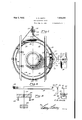
- Figure 1 is a plan view of my improved gas reversing valve
- Fig. 2' is a longitudinal sectional view through the gas reversing valve
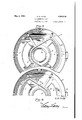
- Fig. 3 is a plan view of the sealing pan with the turtle valve shown in section and the spider in elevation,
- Fig. 4 is a view similar to Fig. 3 with the turtle shown reversed
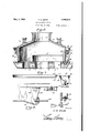
- Fig. 5 is a cross sectional view on the line 5-'5 of Fig. 1,
- Fig. 6 is a detail sectional View showing the weights of the reversing mechanism in a different position than shown in Fig. 5,
- Fig. 7 is a cross sectional view on the line 7-7 of Fig. 1,
- Fig. :8 is a detail sectional view showing the track .and trucks for supporting the turtle valve.
- Fig. '9 is .a detail sectional view of the thrust bearings.
- the reversing valve is shown to comprise a circular base or sealing pan 1, preferably formed of cast iron, in which there are formed openings or ports 2, 3 and 41.
- These ports are of the gen-v eral shape shown in Fig. 3, the ports 2 and-3 being arcuate, and the port l beingciicular, the walls of all of the ports preferably rising to the top of the sealing pan, as shown best in Fig.2, the ports 2 and 3 connect with the fiues which leadto the checkers on opposite sides of the furnace and the port 4 connects with a flue which leads to the stack, these parts a being of the usual and well known construction and hence not being illustrated.
- the ports 2 and 3 are of the gen-v eral shape shown in Fig. 3, the ports 2 and-3 being arcuate, and the port l beingciicular, the walls of all of the ports preferably rising to the top of the sealing pan, as shown best in Fig.2, the ports 2 and 3 connect with the fiues which leadto the check
- sealing pan is filled with water, to the level indicated at W, and has an overflow 5 which is provided with a drain 6.
- the turtle valve 7 is a box preferably formed of sheet metal, and provided with a closed top and sides and havingan open bottom.
- the turtle valve is of such size as to simultaneously establish communication between the center port 4 and one of the side ports 2 or 3, as best shown in Figs. 3 and a.
- the valve, as shown, is preferably formed substantially triangular'in horizontal cross section and is provided with curved portions in the side walls to conform to the curvature the dome thereof with a port 11 for the admission of producer gas which. when the orts are in the position shown in Fig. 2, follows the path indicated by the arrow-heads to the port 2 in the sealing pan and up through the checkers to the furnace where it burns.
- the above mentioned spider 8 which supports the turtle valve preferably is formed with a central ring 12 having arm-s13 extending therefrom at a tangent to support the side walls of the turtle valve 7, the arms being connected terminally by the arcuate arm. 14 for the same purpose.
- the ring and arms 13 and 14 are recessed to provide a seat 15, as shown in Fig. 2, to receive the bottom edge of the secured to the arm '16.
- the unitary integral structure comprising the ring12, arms 13, 14, 16 and 17 constitutes-thespider as a whole and hereinafter this structure will be referred to as the spider.
- the spider is suspended from the housing 9 and for this purpose a circular angle iron 18 is preferably riveted to the upper ends of the arm v16 of the spider.
- a plurality of trucks 19 are secured to the bottom face of the angle iron. These trucks ride on a circu lar track 20-formed of angle iron and preferably riveted to the exterior of the housing.
- the spider 8 and the turtle valve 7 are suspended from the housing and can be revolved as aunit about the central vertical axis of the housing to permit of the turtle valve being reversed from the position shown in Fig. 3 to that shown in Fi g. L whereby to efiect a reversal of the direction of flow of the furnace gases.
- the turtle valve is in the position shown in Fig. 2 or in the reversed position 'shown' in Fig. l,'the lower edge of the valve, and also the spider 8 uponwhich the valve rests, are below the surface of the water in the sealing pan-and aretherefore below the tops of the ports 2, 8and l. It is apparent then that before a reversal can take place, the spider and also the turtle valve must be raised in order that the framework of the spider may pass above and-over the ports as the turtle valve is moved from the position shown in Fig. 3 to that shown in Fig. l and vice versa. This is accomplished as follows.
- a circular angle iron 22 is riveted or otherwise rigidly secured to the circular angle 18 and forms a guide for operating cable '23 which encircles the circular angle iron 18, as shown in Fig. 1.
- the ends of the operating cable pass over sheaves 24 and are attached to a. cable drum '25, as best shown in Fig. 7, which is manually operated by a crank 26.
- a counter-balance cable 2'? is also terminally secured to the circular angle iron 18, as shown at 28, and passes along the guide angle 22 and between spaced sheaves 29 disposed horizontally on a vertical support 30. From thence the counter-balance cable passes over a vertically disposed sheave 31 carried by a hanger 32 and is terminally fixed to a light counter-weight 33.
- the light counter-weight in turn carries a heavier counter-weight 34: over only such part of its travel as is necessary to balance the weight of the spider and turtle valve during the rise'and fall thereof while the trucks 19 are entering or leaving the seats 21.
- a reversing valve for regenerative furnaces comprising a base sealing pan adapted to contain a sealing fluid, said pan having a centrally disposed stack port and diametrically opposite gas ports, a stationary housing adapted to enter said pan and extend into said sealing fluid, said housing having a gas port, a turtle valve adapted to enter said pan and extend into said sealing fluid, means rotatably suspending the valve at the bottom edge from the exterior of the wall of the housing, and means disposed exteriorly of the housing and the pan for rotating said valve to selectively connect either of said gas ports with said stack port.
- a reversing valve for regenerative furnaces comprising a base sealing pan having diametrically opposite gas ports and a central stack port between the gas ports, a stationary housing extending into said pan below the level of said sealing medium and having-a gas port, a spider rotatably mounted on the exterior of said housing and extending intotsaid sealing pan, a turtle valve carried by said spider and adapted to selectively connect either of said gas ports with said stack port, and means disposed exteriorly of said housing and said pan for rotating said spider.
- a reversing valve for regenerative furnaces comprising a base sealing pan adapted to contain a sealing fluid and having a centrally disposed stack port and gas ports on opposite sides of the stack port, a stationary housing extending into said pan below the sealing medium level thereof, a spider disposed in said pan below said sealing medium level and having arms projecting underneath said housing and extending upwardly along the exterior thereof, a circular angle iron surrounding said housing and connecting said arms, trucks carried by said an le iron, a track fixed to the housing and supporting said trucks, "an operating cable disposed on said tle valve carried by said spider Within said pan and extending belovv the level of said sealing medlum, said valve being adapted to connect either of said gas ports with said stack port.
- a reversing valve for regenerative furnaces comprising a base sealing pan having a centrally disposed stack port and gas ports on opposite sides thereof, a stationary housing extending into said sealing pan, a spider disposed withinsaid sealing pan and rotatable about the vertical central axis of said housing, a turtle valve carried by said spider and extending into said pan and adapted to selectively connect either of said gas ports with said stack port, said pan being adapted to contain a sealing medium, means disposed exteriorly of the housing for rotating said spider, and counter-balance means disposed exteriorly of the housing for assisting in the rotation'of said spider and turtle valve.
- Areversing valve for regenerative furnaces comprising a basesealing pan adapted to contain a sealing fluid, and having a stack port and a pair-of gas ports, a stationary housing projecting into said panbelow the sealing fluid level, .a spider disposed in said pan, a. turtle valve carried by said spider adapted to -selectively connect either of said gas portswit saidstack port, said ports extending above the level of said sealing med1um,a track on the exterior of sald housing,
- a reversing valve for regenerative/furnaces comprising a base sealing pan adapted to contain a sealing fluid and having a stack port and spaced gas ports, a stationary housing projecting into said pan below the sealing fluid level, a spider rotatably mounted upon the exterior of said housing and-normally disposed within said pan below thesealing fluid level, means for mounting said spider for verticalmovementrelative tosaid pan whereby the spider may clear said pan to" permit rotation of the spider, a valve carried by the spider adapted to selectively connect said stack port with either oi said gas ports, means for rotating said spider disposed exteriorly of said housing, counter-balance means for moving said spider vertically, and stops operatively connected to said spider and said housing for limiting rotary movement of said spider.
- a reversing valve for regenerative furnaces comprising a base sealing pan adapted I to centain' a sealing fluid and having a stack housing projecting into said pan 'below the sealing fluid level, a spider disposed in said pan, a turtle valve carried by said spider adapted to selectively connect either of said gas ports with said stack port, said ports extending above the level of said sealing medium, a track on said housing having depressions therein, trucks carried by said spider and riding on said track and adapted to seat in said depressions to dispose said valve in operative position, a cable and cable drum operatively connected to said spider for rotating the spider and turtle valve as a unit, a
- a reversing valve for regenerative furnaces comprising a base sealing pan adapted to contain a sealing fluid, and having a central stack port and gas ports on opposite sides of the staclr. port, a stationaryhousing projecting into said pan below the sealing fluid level, a spider normally disposed in'said pan,
- a reversing valve for regenerativefurnaces comprising a base sealing pan adapted to contain a sealing fluid and having a; stack port and opposite gas ports, a stationary housing projecting intosaid-pan, a spider and forming a guide, and a cable supported by the guide angle iron and encircling said guide angle iron and having the ends terminally connected to a cable drum, rotation of said drum in either direction being adapted to rotate said valve and said spider as a unit and selectively position said valve to conneot either of said gas ports with said stack ort.
- a reversing valve for regenerative furnaces comprising a sealing pan adapted to contain a sealing fluid, and having a stack port and a pair of gas ports, a spider disposed in said pan, a turtle valve carried by said spider, a stationary housing having a gas port and projecting into said pan below the sealing fluid level thereof, said ports rising above the sealing fluid level of said pan, means disposed exteriorly of said housing for suspending said spider and said valve for rotation as a unit to dispose said valve in either of its operative positions to selectively connect either of said gas ports with said stack port, counter-balance means disposed exteriorly of said housing for assisting in lifting said spider and said valve above said pan to permit rotation of the spider and drum as a unit, means for limiting rotary movement of the spider and valve in either direction, and means for rotating said spider and valve.
Landscapes
- Engineering & Computer Science (AREA)
- Chemical & Material Sciences (AREA)
- Combustion & Propulsion (AREA)
- Mechanical Engineering (AREA)
- General Engineering & Computer Science (AREA)
- Vertical, Hearth, Or Arc Furnaces (AREA)
Description
May3, 1932. CDSWTH 1,856,516
GAS REVERSING VALVE Filed May 23, 1930 5 SheetsSheut l y c. D. SMITH GAS REVERSING VALVE Filed May 25, 1930 5 Sheets-Sheet 2 May 3, 1932. c. D. SMITH GAS REVERSING VALVE F Filed May 23, 1950 3 Sheets-Sheet 3 L2 .27. Emil]:
WOT IMP Patented May 3, 1932 PATENT OFFICE CARL D. SMITH, OF WASHINGTON, PENNSYLVANIA GAS BEVEBSING VALVE Application filed May 23,
This invention relates to producer gas reversing valves for regenerative furnaces.
Producer gas reversing valves have hitherto been difficult to clean and care for. The 5 usual practice is to shut off the gas once a week, open up the valve and clean out all deposits of soot, dirt and tar from the inside. The supports for the valve are usually disposed inside the sealing pan and under the 10 water and these frequently become fouled by accumulations of tar and soot which can not be readily cleaned out unless the valve is opened up so that the workman may have arr cess to the bearings and this, of course, means 15 interruption in the operation of the furnace. The present invention has for an object, therefore, to dispose" all operating mechanism and supports for the turtle valve on the exterior of the apparatus where they cannot become fouled by tar and soot, thus leaving the bottom of the sealing pan free of all supporting obstacles. Cleaning tools can readily reach all partsof the pan. A further advantage is that this cleaning process may be carried out at any time without shutting off the gas and without interfering in any manner with the normal operation of the furnace.
Reversing valves of the ordinary type require considerable manual labor to reverse the valve.- Frequently it takes the combined efforts of two laborers to reverse, particularly when the reversing mechanism becomes fouled with tar and soot.
A further object :of the present invention, therefore, is to provide reversing mechanism by means of which the valves may be reversed, even when fouled, with minimum manual efi'ort.
lVith the above and other objects in view, the invention consists of certain novel details of construction and combinations of parts hereinafter fully described and claimed, it being understood that various modifications may be resorted to within the scope of the appended claims without departing from the spirit or sacr iiicing any .of the advantages of the invention.
In the accompanying drawings forming part of this specification:
1930. Serial No. 455,047.
Figure 1 is a plan view of my improved gas reversing valve,
Fig. 2' is a longitudinal sectional view through the gas reversing valve,
Fig. 3 is a plan view of the sealing pan with the turtle valve shown in section and the spider in elevation,
Fig. 4 is a view similar to Fig. 3 with the turtle shown reversed,
Fig. 5 is a cross sectional view on the line 5-'5 of Fig. 1,
Fig. 6 is a detail sectional View showing the weights of the reversing mechanism in a different position than shown in Fig. 5,
Fig. 7 is a cross sectional view on the line 7-7 of Fig. 1,
Fig. :8 is a detail sectional view showing the track .and trucks for supporting the turtle valve. and
Fig. '9 is .a detail sectional view of the thrust bearings.
Ordinarily, producer gas as a fuel for a regenerative furnace, and air for the com bustion thereof, pass through reversing valves into separate *fiues which lead to checker chambers. Here, both air and gas rise through highly heated checker brick to the furnace ports where they mix and burn with a high temperature as they pass through the furnace. The burnt gases leave on the opposite side :of the furnace through ports of similar construction to those through which they enter, and then pass downward through checker brick which absorbs heat from the hot gases. These burnt gases then follow flues to the reversing valves through which they pass on the way to the stack and with- .out coming in contact with the fresh supply of incoming gas and air.
The fact that both the air and gas become highly heated in the checkers before they mix and burn in the furnace adds much to the temperatures attainable. It is easily seen that should the direction of flow be maintained for a considerable period of time, the checkers on the inlet side would gradually cool off, resulting in much lower furnace temperature while the checkers on the outlet side would build up heat. Accordingly, it is desirable'to periodically change the direction of flow through the furnace and checkers, so that much higher furnace temperatures can be maintained, and for this purpose I have provided the reversing valve which will now be described.
Referring now to the drawings, the reversing valve is shown to comprise a circular base or sealing pan 1, preferably formed of cast iron, in which there are formed openings or ports 2, 3 and 41. These ports are of the gen-v eral shape shown in Fig. 3, the ports 2 and-3 being arcuate, and the port l beingciicular, the walls of all of the ports preferably rising to the top of the sealing pan, as shown best in Fig.2, the ports 2 and 3 connect with the fiues which leadto the checkers on opposite sides of the furnace and the port 4 connects with a flue which leads to the stack, these parts a being of the usual and well known construction and hence not being illustrated. The
. sealing pan is filled with water, to the level indicated at W, and has an overflow 5 which is provided with a drain 6.
The turtle valve 7 is a box preferably formed of sheet metal, and provided with a closed top and sides and havingan open bottom. The turtle valve is of such size as to simultaneously establish communication between the center port 4 and one of the side ports 2 or 3, as best shown in Figs. 3 and a. The valve, as shown, is preferably formed substantially triangular'in horizontal cross section and is provided with curved portions in the side walls to conform to the curvature the dome thereof with a port 11 for the admission of producer gas which. when the orts are in the position shown in Fig. 2, follows the path indicated by the arrow-heads to the port 2 in the sealing pan and up through the checkers to the furnace where it burns. The
burnt gases leaving the, furnace follow the path indicated by the arrow-heads through the port 3, turtle valve 7 and port 4 to the stack. The metal cylindrical side wall of the housing extends below the fire brick lining and dips beneath the surface of the water in the sealing pan, thus making a gas-tight closure. V
The above mentioned spider 8 which supports the turtle valve preferably is formed with a central ring 12 having arm-s13 extending therefrom at a tangent to support the side walls of the turtle valve 7, the arms being connected terminally by the arcuate arm. 14 for the same purpose. The ring and arms 13 and 14: are recessed to provide a seat 15, as shown in Fig. 2, to receive the bottom edge of the secured to the arm '16. The unitary integral structure comprising the ring12, arms 13, 14, 16 and 17 constitutes-thespider as a whole and hereinafter this structure will be referred to as the spider.
The spider is suspended from the housing 9 and for this purpose a circular angle iron 18 is preferably riveted to the upper ends of the arm v16 of the spider. A plurality of trucks 19 are secured to the bottom face of the angle iron. These trucks ride on a circu lar track 20-formed of angle iron and preferably riveted to the exterior of the housing. Thus, the spider 8 and the turtle valve 7 are suspended from the housing and can be revolved as aunit about the central vertical axis of the housing to permit of the turtle valve being reversed from the position shown in Fig. 3 to that shown in Fi g. L whereby to efiect a reversal of the direction of flow of the furnace gases. f
.;VVhen the turtle valve is in the position shown in Fig. 2 or in the reversed position 'shown' in Fig. l,'the lower edge of the valve, and also the spider 8 uponwhich the valve rests, are below the surface of the water in the sealing pan-and aretherefore below the tops of the ports 2, 8and l. It is apparent then that before a reversal can take place, the spider and also the turtle valve must be raised in order that the framework of the spider may pass above and-over the ports as the turtle valve is moved from the position shown in Fig. 3 to that shown in Fig. l and vice versa. This is accomplished as follows. When the turtle valve is in either of its operative positions the trucks 19 rest in depressions 21 formed inthe track 20, as best shown in Fig. 8. When a reversal ismade thetrucks roll up and out of the depressions 21 and onto the track 20 at which elevation there is ample clearance for the spider topass over the ports 2, 3 and 4. r 1
The turtle valve and .the spider naturally have considerable weight, and, therefore, considerable pull is necessary when starting to reverse in order to pull thetrucks 19 up and out of the depressions orseats 21. This operation is made easy by a counter-balance, best shown in Figs. 1, 5 and 6, and which will now be described. I V A circular angle iron 22 is riveted or otherwise rigidly secured to the circular angle 18 and forms a guide for operating cable '23 which encircles the circular angle iron 18, as shown in Fig. 1. The ends of the operating cable pass over sheaves 24 and are attached to a. cable drum '25, as best shown in Fig. 7, which is manually operated by a crank 26. By turning the crank first in one direction and then the other, the turtle valve is readily changed from one position to the otheras will be understood.
A counter-balance cable 2'? is also terminally secured to the circular angle iron 18, as shown at 28, and passes along the guide angle 22 and between spaced sheaves 29 disposed horizontally on a vertical support 30. From thence the counter-balance cable passes over a vertically disposed sheave 31 carried by a hanger 32 and is terminally fixed to a light counter-weight 33. The light counter-weight in turn carries a heavier counter-weight 34: over only such part of its travel as is necessary to balance the weight of the spider and turtle valve during the rise'and fall thereof while the trucks 19 are entering or leaving the seats 21.
Thus, while the trucks 19 are. passing from the position shown in full lines in Fig. 8 to the position shown in dotted lines in Fig. 8, theheavy counter-Weight 34 descends and just comes to rest on stationary/supports '35, as best shown in Fig. 6, as the trucks arrive at the position shown in dotted lines in Fig. 8 where the heavy counter-weight 34: is no longer needed. The lighter counter-weight 33 continues to gravitate until the fixed terminal 28 of the counter-balance cable 2'? passes the center between the sheaves 29 when it again raises and lifts the heavier counterweight 34 just as the trucks 19 start to enter the seats 21 at the end of a reverse.
In the operation when the turtle valve is'in the position shown in Figs. 2 and 3 producer gas follows the path indicated by the arrowheads through the ports 11 in the housing and 2 in the sealing pan to the checkers and from thence to the furnace where it burns. The burnt gases leaving the furnace follow the path indicated by the arrow-head through the port 3 of the sealing pan through the turtle valve 7 and through the port l of the sealing pan to the stack. After a reverse, that is when the turtle valve is in the position shown in Fig. 4:, the producer as passes through the port 3 to the checkers and the burnt gases pass from the furnace through the ports 2 and at on their way to the stack.
It will be observed from the above description that all of the operating mechanism and supports for the turtle valve are on the exterior of the apparatus where they cannot become fouled by tar and soot, thus leaving the bottom of the sealing pan free from all supporting obstructions. Consequently, cleaning tools or even a steam jet or suction hose may be used to easily reach all parts of the pan, to effect the removal of accumulated tar, soot and dirt therefrom Without shu't ting off the gas or interfering in any manner with the normal operation of the furnace.
It will be further pointed out that by virtue of the novel counter-balance weights for assisting in making a reverse, the manual labor incident thereto is substantially decreased so that minimum effort will accomplish the same result hitherto requiring the combined efforts of several laborers.
It will be apparent that due to the tension in the operating cable 23, as well as in the counter-balance cable 27, there is a tendency for horizontal thrust of the angle iron 18 relatively to thehousing 9 and the angle iron 22. In order to take care of this, thrust bearings 36 are secured to the angle iron 18, as best shown in Fig. 9, and bear against the housing. as shown best in Fig. 1.
Having thus described the invention, I claim:
1. A reversing valve for regenerative furnaces comprising a base sealing pan adapted to contain a sealing fluid, said pan having a centrally disposed stack port and diametrically opposite gas ports, a stationary housing adapted to enter said pan and extend into said sealing fluid, said housing having a gas port, a turtle valve adapted to enter said pan and extend into said sealing fluid, means rotatably suspending the valve at the bottom edge from the exterior of the wall of the housing, and means disposed exteriorly of the housing and the pan for rotating said valve to selectively connect either of said gas ports with said stack port.
.2. .A reversing valve for regenerative furnaces comprising a base sealing pan having diametrically opposite gas ports and a central stack port between the gas ports, a stationary housing extending into said pan below the level of said sealing medium and having-a gas port, a spider rotatably mounted on the exterior of said housing and extending intotsaid sealing pan, a turtle valve carried by said spider and adapted to selectively connect either of said gas ports with said stack port, and means disposed exteriorly of said housing and said pan for rotating said spider.
3. A reversing valve for regenerative furnacescomprising a base sealing pan adapted to contain a sealing fluid and having a centrally disposed stack port and gas ports on opposite sides of the stack port, a stationary housing extending into said pan below the sealing medium level thereof, a spider disposed in said pan below said sealing medium level and having arms projecting underneath said housing and extending upwardly along the exterior thereof, a circular angle iron surrounding said housing and connecting said arms, trucks carried by said an le iron, a track fixed to the housing and supporting said trucks, "an operating cable disposed on said tle valve carried by said spider Within said pan and extending belovv the level of said sealing medlum, said valve being adapted to connect either of said gas ports with said stack port. c r
- 4. A reversing valve for regenerative furnaces comprising a base sealing pan having a centrally disposed stack port and gas ports on opposite sides thereof, a stationary housing extending into said sealing pan, a spider disposed withinsaid sealing pan and rotatable about the vertical central axis of said housing, a turtle valve carried by said spider and extending into said pan and adapted to selectively connect either of said gas ports with said stack port, said pan being adapted to contain a sealing medium, means disposed exteriorly of the housing for rotating said spider, and counter-balance means disposed exteriorly of the housing for assisting in the rotation'of said spider and turtle valve.
5. Areversing valve for regenerative furnaces comprising a basesealing pan adapted to contain a sealing fluid, and having a stack port and a pair-of gas ports, a stationary housing projecting into said panbelow the sealing fluid level, .a spider disposed in said pan, a. turtle valve carried by said spider adapted to -selectively connect either of said gas portswit saidstack port, said ports extending above the level of said sealing med1um,a track on the exterior of sald housing,
trucks carried by said spider and riding on said. track, there being depressions in said track, means for lifting said trucks out of said depressions whereby to raise said spider and said valve, to clear said pan to permit a rotationof said valve, and a cable and cable drum o'peratively connected to said spider for rotating the spider and turtle valve as a unit.
6. A reversing valve for regenerative/furnaces comprising a base sealing pan adapted to contain a sealing fluid and having a stack port and spaced gas ports, a stationary housing projecting into said pan below the sealing fluid level, a spider rotatably mounted upon the exterior of said housing and-normally disposed within said pan below thesealing fluid level, means for mounting said spider for verticalmovementrelative tosaid pan whereby the spider may clear said pan to" permit rotation of the spider, a valve carried by the spider adapted to selectively connect said stack port with either oi said gas ports, means for rotating said spider disposed exteriorly of said housing, counter-balance means for moving said spider vertically, and stops operatively connected to said spider and said housing for limiting rotary movement of said spider.
71. A reversing valve for regenerative furnaces comprising a base sealing pan adapted I to centain' a sealing fluid and having a stack housing projecting into said pan 'below the sealing fluid level, a spider disposed in said pan, a turtle valve carried by said spider adapted to selectively connect either of said gas ports with said stack port, said ports extending above the level of said sealing medium, a track on said housing having depressions therein, trucks carried by said spider and riding on said track and adapted to seat in said depressions to dispose said valve in operative position, a cable and cable drum operatively connected to said spider for rotating the spider and turtle valve as a unit, a
counter-balance weight on said cable, a counter-balance weight onsaid cable above the first named counter-balance weight for assisting in raising said trucks out of said depressions whereby said valve may clear said pan to permit rotation of said valve, and means for supporting the last named counter-balance Weight when said trucks have moved out of or into said depressions.
8. A reversing valve for regenerative furnaces comprising a base sealing pan adapted to contain a sealing fluid, and havinga central stack port and gas ports on opposite sides of the staclr. port, a stationaryhousing projecting into said pan below the sealing fluid level, a spider normally disposed in'said pan,
'a turtle valve carried by said spider and normally extending beloW the sealing fluid level ofsaid pan,said valve being adapted to selectively connect either of said gas ports with said stack ports, a track on theexterior of said housing, trucks carried by said spider and riding on said track, a cable and drum operatively connected to saidspider for rotating said'spider, there being depressions in saidtrack normallyi receiving said trucks to position said turtle valve in either of its operative positions, a cable and cable drum operatively connected to said spider for rotating the spider and turtle valve as a unit, a counter-balance weight on said cable for assisting, in rotating said valve and spider, and a second counter-balance weight on said cable'above the first named counter-balance weight for assisting in moving said trucks out of said depressions to permit said valve and spider to clear said pan prior to rotation thereof.
9. A reversing valve for regenerativefurnaces comprising a base sealing pan adapted to contain a sealing fluid and having a; stack port and opposite gas ports, a stationary housing projecting intosaid-pan, a spider and forming a guide, and a cable supported by the guide angle iron and encircling said guide angle iron and having the ends terminally connected to a cable drum, rotation of said drum in either direction being adapted to rotate said valve and said spider as a unit and selectively position said valve to conneot either of said gas ports with said stack ort. p 10. A reversing valve for regenerative furnaces comprising a sealing pan adapted to contain a sealing fluid, and having a stack port and a pair of gas ports, a spider disposed in said pan, a turtle valve carried by said spider, a stationary housing having a gas port and projecting into said pan below the sealing fluid level thereof, said ports rising above the sealing fluid level of said pan, means disposed exteriorly of said housing for suspending said spider and said valve for rotation as a unit to dispose said valve in either of its operative positions to selectively connect either of said gas ports with said stack port, counter-balance means disposed exteriorly of said housing for assisting in lifting said spider and said valve above said pan to permit rotation of the spider and drum as a unit, means for limiting rotary movement of the spider and valve in either direction, and means for rotating said spider and valve.
In testimony whereof I aflix my signature.
CARL D. SMITH. [L. s.]
Priority Applications (1)
| Application Number | Priority Date | Filing Date | Title |
|---|---|---|---|
| US45504730 US1856516A (en) | 1930-05-23 | 1930-05-23 | Gas reversing valve |
Applications Claiming Priority (1)
| Application Number | Priority Date | Filing Date | Title |
|---|---|---|---|
| US45504730 US1856516A (en) | 1930-05-23 | 1930-05-23 | Gas reversing valve |
Publications (1)
| Publication Number | Publication Date |
|---|---|
| US1856516A true US1856516A (en) | 1932-05-03 |
Family
ID=23807155
Family Applications (1)
| Application Number | Title | Priority Date | Filing Date |
|---|---|---|---|
| US45504730 Expired - Lifetime US1856516A (en) | 1930-05-23 | 1930-05-23 | Gas reversing valve |
Country Status (1)
| Country | Link |
|---|---|
| US (1) | US1856516A (en) |
Cited By (1)
| Publication number | Priority date | Publication date | Assignee | Title |
|---|---|---|---|---|
| US2437144A (en) * | 1944-08-21 | 1948-03-02 | Wisconsin Alumni Res Found | Fluid cooled four-way valve |
-
1930
- 1930-05-23 US US45504730 patent/US1856516A/en not_active Expired - Lifetime
Cited By (1)
| Publication number | Priority date | Publication date | Assignee | Title |
|---|---|---|---|---|
| US2437144A (en) * | 1944-08-21 | 1948-03-02 | Wisconsin Alumni Res Found | Fluid cooled four-way valve |
Similar Documents
| Publication | Publication Date | Title |
|---|---|---|
| US1856516A (en) | Gas reversing valve | |
| US2097932A (en) | Soaking pit | |
| US1872057A (en) | Cupola furnace | |
| US1914716A (en) | Copper melting furnace | |
| US1041523A (en) | Sand-drier. | |
| US1596843A (en) | Water-cooled-damper construction | |
| US955600A (en) | Valve. | |
| USRE15552E (en) | A corpo | |
| US1499017A (en) | Reversing valve for furnaces | |
| US1137378A (en) | Melting-furnace. | |
| US1379696A (en) | Reversing-valve mechanism | |
| US1457557A (en) | Furnace | |
| US793668A (en) | Coke-oven attachment. | |
| US878213A (en) | Valve for furnaces. | |
| US2409442A (en) | Method and apparatus for cleaning furnace checkers and flues | |
| US1487332A (en) | Reversing apparatus for heating furnaces | |
| US916695A (en) | Reversing-valve for regenerative furnaces. | |
| US1492529A (en) | Furnace | |
| GB359941A (en) | Improvements in or relating to apparatus for heating bitumen, tar or the like | |
| US908353A (en) | Reversing-valve for furnaces. | |
| US3473A (en) | Improvement in sugar-boilers | |
| US1669696A (en) | Furnace-slagging apparatus | |
| US1998349A (en) | Rotary and semirotary furnace | |
| US1009822A (en) | Reversing-valve for regenerative furnaces. | |
| US1249701A (en) | Hot-blast stove. |