US1856515A - Typographical magazine - Google Patents
Typographical magazine Download PDFInfo
- Publication number
- US1856515A US1856515A US469008A US46900830A US1856515A US 1856515 A US1856515 A US 1856515A US 469008 A US469008 A US 469008A US 46900830 A US46900830 A US 46900830A US 1856515 A US1856515 A US 1856515A
- Authority
- US
- United States
- Prior art keywords
- magazine
- frame
- matrices
- cover
- latch
- Prior art date
- Legal status (The legal status is an assumption and is not a legal conclusion. Google has not performed a legal analysis and makes no representation as to the accuracy of the status listed.)
- Expired - Lifetime
Links
- 239000011159 matrix material Substances 0.000 description 11
- 238000005266 casting Methods 0.000 description 3
- 108091006146 Channels Proteins 0.000 description 2
- 210000005069 ears Anatomy 0.000 description 2
- 238000005192 partition Methods 0.000 description 2
- LFVLUOAHQIVABZ-UHFFFAOYSA-N Iodofenphos Chemical compound COP(=S)(OC)OC1=CC(Cl)=C(I)C=C1Cl LFVLUOAHQIVABZ-UHFFFAOYSA-N 0.000 description 1
- 235000000396 iron Nutrition 0.000 description 1
- 239000002184 metal Substances 0.000 description 1
- 229920000136 polysorbate Polymers 0.000 description 1
- 230000000717 retained effect Effects 0.000 description 1
Images
Classifications
-
- B—PERFORMING OPERATIONS; TRANSPORTING
- B41—PRINTING; LINING MACHINES; TYPEWRITERS; STAMPS
- B41B—MACHINES OR ACCESSORIES FOR MAKING, SETTING, OR DISTRIBUTING TYPE; TYPE; PHOTOGRAPHIC OR PHOTOELECTRIC COMPOSING DEVICES
- B41B11/00—Details of, or accessories for, machines for mechanical composition using matrices for individual characters which are selected and assembled for type casting or moulding
- B41B11/06—Storage devices for matrices or space bands
Definitions
- Our invention relates to improvements in typographical magazines,used for the storage of the matrices which are used in a machine of this type in the casting of type in lines.
- a magazine containing the matrices, is removably attached to a linotype, intertype, or similar machine, holding the matrices for a certain kind of type, and, when it becomes necessary to make a change in the type face cast by the machine, the magazine must be removed, and another one put on the machine, or the matrices removed from the magazineand other matrices substituted.
- An object of our invention is to provide a series of storage magazines, in which the vari ous types of matrices may be stored, and
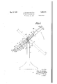
- Fig. 1 is a side'elevational view of the tiltable table or frame, with the magazines sup ported'thereon.
- Fig. 2 is a plan view of the table tipped' showing the magazines in place.
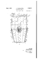
- Fig. 3 is a sectional view on the line 33 of Fig. 2.
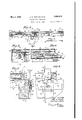
- Fig. 4 is a detail side elevational View of the lock bar used with the storage magazine.
- Fig. 5 is a detail view of the matrix releasing mechanism employed with the matrix lock on the standard magazine.
- Fig. 6 is a transverse sectional View on the line 66 of Fig. 5.
- Fig. 7 is a sectional detail view of the releasing mechanism employed with the cover onthe back of the standard magazine, taken on line 77 of Fig. 8.
- Fig. 8 is an elevational View of the mechanism shown in Fig. 7 looking from the right.
- Fig. 9 is a sectional View on the line 99 of Fig. 7.
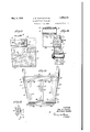
- Fig. 10 is a detail sectional view of the pivotal support for the table top.
- Fig. 11 is a plan view of the lower part of the table top, showing means for centering the standard magazine thereon, and
- Fig. 12 is a detail View of the positioning brackets for the cover releasing levers.
- the table top, or frame 1 is pivotally supported by means of the studs 2 on standards or legs 3, only one of which is shown. 4 indicates stop members having inclined faces 5 corresponding to the angle at which the standard magazine is mounted in the type casting machine and secured to the legs 3 with the bolts 6. Angle-shaped cradles 7, or irons, arescrewed to the opposite side of the frame 1, as indicated with the screws 8, and having depending lugs or extensions 9, which receive the pins 2, on the standards 3 for connecting the frame 1 and legs 3.
- the frame 1 comprises the side stiles 10, top cross bar or stile 11, bottom rail 12, and intermediate cross braces, rails, or bars 13, 14 and 15.
- a matrix magazine used on a type casting machine, is supported on the lower half of the frame 1.
- the magazine shown in the drawings is that used with the intertype the strips 24, in which the matrices 25 are" slidably mounted and guided. These rooves,
- the standard magazine is equipped with a centering bar 36, (see Fig.6) ,usedito center the-magazine on. the type-making machine.
- Two centering bars '37,. are secured tog-thecross rails 14' and 15,.and' the bar 36- fits. in the space 381b'etw'een them,
- the rod is pulled out, leaving the matrices free the magazines. It is also formed with pan titions 51 and grooves 52, the grooves 52 reg istering in spacing and width with the grooves 46 of the storage magazine, and being tapered at the ends 53 to register with the tapered grooves 23 of-the standardmagazine 16.
- the member 40 is madeof metal to avoid fast wearingin the tapered grooves, and acts as a transfer entrance or bridge 3 between the two magazines.
- FIG. 3 A cover plate GOispi-votally secured to the siderails-lO of theframe 1 by means of the transverse shaft, ⁇ or rod 61.
- a U shaped strap 62 is secured to the cover bythe screw 63, movable in the slot 64 in this lever. The longer end 62 of the-U,-
- shaped strap 62 is guided in .an upward and downward direction by the guide strips, 66 and 67.
- lever. handle 70 When it is desired to'lower the gateorcover 38, the lever. handle 70 is pushed. outward slightly, disengaging it from. the; shoulder, or notch 71, then downwardly, until it is again engaged in thelower notch 7 4 of theblock 72. This downward movement 'ofthe. lever 7 0,
- a cross piece 77 is 1 secured to the top rail 11 by the screws 7 8.
- Wedge-shaped notches 79 are formed in this cross piece.
- a bar 80 formed with the wedgeshaped extensions 81 and handle 82, is slidably mounted on the top rail 11, with the extensions 81 engaging in the notches 79.
- a main frame member in combination, a main frame member, a support therefor, means for pivotally supporting the main frame member on the support to permitit to tilt in opposite directions, means for limiting the tilting movement, the frame member being designed to receive two matrix receiving frames having grooves to receive the matrices in an aligned relation to each other, the matrices being normally retained against movement in one ma trix frame by a latch device, an eccentrically mounted shaft for actuating the latch device, for releasing the matrices, when the main frame is tilted, a second latch or cover device located at the opposite end of a matrix frame, means for operating the second latch, whereby the matriceswill be transferred from one aligned frame to the other.
- a main supporting frame means for pivotally supporting the main frame, two matrix receiving frames mounted on the main frame, each of the matrix receiving frames having aligned grooves to receive the matrices, means for retaining said frames on the main frame, comprisin a slidable bar formed with projections, a fixed bar on the main frame formed with recesses for receiving the said rejections, whereby, when the slidable bar is operated, the two matrix frames will be forced toward each other, a transfer or bridge piece adjacent the ends of the two frames, a gate member normally closing the discharge end of one frame, means for actuating the discharge member, when matrices are to be transferred from one frame to another comprising a rotatable latch, a vertically slidable member having a depending end for operating the latch to release the gate member, means for operating the vertically movable member comprising a lever having an elongated slot therein to receive a pin on the vertically movable member, the lever member being pivotally attached to the main frame
- a tiltably supported main frame means for limiting the tilting movement in opposite directions, a magazine frame and a storage frame for matrices supported on the main frame, means for moving the frames into close relation, so that the grooves in the two frames are in alignment, a latch for normally retaining the matrices against release in one frame, an eccentrically mounted shaft for operating the latch, the main frame having a recess formed therein, a gate or cover for closing the end of one of the matrix frames, means for moving the gate into the recess of the main frame comprising a U- shaped member slidably mounted on the main frame, a latch which normally retains the gate in closed position, one end of the U- shaped member being normally in contact with the latch to move the same against the latch apparatus, and to open the gate member, and means for operating the U-shaped member comprising a lever pivoted to the main frame and means for retaining the lever in either its operative or inoperative position.
- an apparatus for transferring matrices from one frame to another comprising a main supporting frame, means for tiltably mounting said frame on a support, said matrix receiving frames being mounted on the main tiltable frame, the adjacent ends of the said frames being in alignment, means for normally closing the passageway from one frame to another, means for operating the closing means comprising a pivotally mounted latch mounted on the'closing means, a slidable: member ing the slidable member to rotate the latch leverattached 'to the main frame, a notched mnember secured torthe mam frame and hav- 7 normally engaging the latch means foractuatbut of its engagementwith the gate member ancl for moving the-gate member clear of the passageway, means for retaining the gate member'in th1s open posltlon comprlsmg a ingoppositely disposed notches for retaining thegate'member, either in its opener closed 'POSltlOll.
Landscapes
- Portable Nailing Machines And Staplers (AREA)
Description
May 3, 1932. J. w. SH|ELDS ET AL TYPOGRAPHICAL MAGAZINE Filed July 19, 1930 4 Sheets-Sheet INVENTORS, r/Mrz hf Jkz'elds,
A TTORNEY.
4 Sheets-Sheet ATTORNEY.
J. w. SHIELDS ET AL TYPOGRAPHICAL MAGAZINE Filed July 19, 1930 w Q 60 'l I {I i w. I ll i ii I II II II a Qi J 1. 5 15: .5 5 iyd iin :ZIIIIZZIIIIIIII: i i
May 3, 1932.
May 3, 1932. J. w. SHIELDS ET AL TYPOGRAPHICAL MAGAZINE 4 Sheets-Sheet 5 IIIIIIIIIIIIIIIIII w s m w Filed July 19, 1930 INVENTORS, rfokrz M 5m flrafiflald J/Ezields,
' ATTORNEY.
TYPQGRAPHI CAL MAGA Z INE ATTORNEY.
Patented May 3, 1932 'UNETED STATES PATENT OFFICE JOHN W. SHTELDS OF BRIDGEPORT, CONNECTICUT, AND ARGHIBALD SHIELDS, OF
' BROOKLYN, NEW YORK TYPOGRAPHICAL MAGAZINE Application filed July 19, 1930. Serial No. 469,008.
Our invention relates to improvements in typographical magazines,used for the storage of the matrices which are used in a machine of this type in the casting of type in lines. At the present time, a magazine, containing the matrices, is removably attached to a linotype, intertype, or similar machine, holding the matrices for a certain kind of type, and, when it becomes necessary to make a change in the type face cast by the machine, the magazine must be removed, and another one put on the machine, or the matrices removed from the magazineand other matrices substituted. 1
An object of our invention is to provide a series of storage magazines, in which the vari ous types of matrices may be stored, and
means for quickly and easily transferring the matrices from the regular magazine used on the machine, to and from the storage magazines. 1
e accomplish this object by the use of a specially constructed table or frame, equipped with mechanism to operate various devices on the standard magazines, and adapted to both support'a-nd align the standard magazine and storage magazine in such away that, when the table or frame is tipped forward or backward, the matrices will slide freely from one magazine into the other.
In the drawings, the standard magazine of the intertype machine is illustrated, but it will be readily understood that our invention is adaptable to any type of magazine now in use.
A preferred form of our invention is illustrated in the acco panying drawings, in which: I v
Fig. 1 is a side'elevational view of the tiltable table or frame, with the magazines sup ported'thereon.
Fig. 2 is a plan view of the table tipped' showing the magazines in place.
Fig. 3 is a sectional view on the line 33 of Fig. 2. r
Fig. 4 is a detail side elevational View of the lock bar used with the storage magazine.
Fig. 5 is a detail view of the matrix releasing mechanism employed with the matrix lock on the standard magazine.
Fig. 6 is a transverse sectional View on the line 66 of Fig. 5.
Fig. 7 is a sectional detail view of the releasing mechanism employed with the cover onthe back of the standard magazine, taken on line 77 of Fig. 8.
Fig. 8 is an elevational View of the mechanism shown in Fig. 7 looking from the right.
Fig. 9 is a sectional View on the line 99 of Fig. 7.
Fig. 10 is a detail sectional view of the pivotal support for the table top.
Fig. 11 is a plan view of the lower part of the table top, showing means for centering the standard magazine thereon, and
Fig. 12 is a detail View of the positioning brackets for the cover releasing levers.
Referring to the drawings in detail, in which like numerals refer to like parts throughout The table top, or frame 1, is pivotally supported by means of the studs 2 on standards or legs 3, only one of which is shown. 4 indicates stop members having inclined faces 5 corresponding to the angle at which the standard magazine is mounted in the type casting machine and secured to the legs 3 with the bolts 6. Angle-shaped cradles 7, or irons, arescrewed to the opposite side of the frame 1, as indicated with the screws 8, and having depending lugs or extensions 9, which receive the pins 2, on the standards 3 for connecting the frame 1 and legs 3. The frame 1 comprises the side stiles 10, top cross bar or stile 11, bottom rail 12, and intermediate cross braces, rails, or bars 13, 14 and 15.
A matrix magazine, used on a type casting machine, is supported on the lower half of the frame 1. The magazine shown in the drawings is that used with the intertype the strips 24, in which the matrices 25 are" slidably mounted and guided. These rooves,
as shown, are tapered at the end, 26, to
facilitate the filling of the same,v with matrices. In order to prevent the matrices from'shdmg outof the magazlne, while it is being handled, it is equipped with an escapement-mechanism at or near. its lower end 22, consisting of a series ofescapement levers 27, one for each. groove, which ens gage the first row of matrices and thereby prevent them from slidingi'o utfi The upper open end 22 .ofthe magazine 16 is protected by the gate or. cover. 28, which is formed with a bottom flange 29,. (see'l. ..ig. 8), to which there is:.securedltwo flat springs 30, which are-inturn secured attheir opposite ends to the cross bar 31 of the magazine 16. The gate, or' cover 28,.is also formedewith two ears OI'I'tOP flanges 32,.which are engaged by the' safety latches 33,.pivotally secured to the side channelss-19 oftthe magazine l6fofithe'pins- 34. The latches 33 are held iii-engagement with the flanges or ears 32 with the springs 35, thereby maintaining the gate or cover 28 in a closed position over theopen: end 21 of the magazine 16.
The standard magazine is equipped with a centering bar 36, (see Fig.6) ,usedito center the-magazine on. the type-making machine. Two centering bars '37,. (see Fig: 11) are secured tog-thecross rails 14' and 15,.and' the bar 36- fits. in the space 381b'etw'een them,
frame 1...
thereby. centering the magazine on the When a is desired to either finer empty a standard magazine with matrices, it is placed'on theframe 1. A'storage magazine,
39, is placed on the upperpart ofthe'frame 1, 'anda short, connecting'cover or bridging plate member issecured to the framebe' tween the standard magazine 16 andthe storage magazine 39. This magazine "is formed with top plate41, bottom plate 42, side chan nels 43, end channel 44, partitions 45,'and grooves, 46,. the grooves 46 registering in spacing and widths with the grooves 23 of magazine is handled.
the standardmagazine16, (see The partitions eXtendbeyo-nd the .end .47 of the storagemagazine 39,.a-nd are formed with holes 48- in the extensions 49. A rod, 50 (see Fig.4) is inserte'dinthe holes48 to prevent the: matrices. from sliding out, when the V hen the storage magazme 39 1s placed on the frame 1, .this
rod is pulled out, leaving the matrices free the magazines. It is also formed with pan titions 51 and grooves 52, the grooves 52 reg istering in spacing and width with the grooves 46 of the storage magazine, and being tapered at the ends 53 to register with the tapered grooves 23 of-the standardmagazine 16. The member 40 is madeof metal to avoid fast wearingin the tapered grooves, and acts as a transfer entrance or bridge 3 between the two magazines.
Before 1 transferring matrices from the standard magazine to the storage magazine, or vice versa, it is necessary to release the escapement or mechanism 27 and the gate or cover 28. The locking mechanism is released by means ofaubar-54 which rests eon-anaeccentric shaft-55. This shaft issupported inrthe bearings 56,; and a crank57 is secured to an end 58 of the-shaft 55. When the crank 57 turned, the eccentriczshaft raises the bar .54, which in turn lifts the tails--58 of-the pivoted escapement fingers 27 ,Ithereby tipping the ends59 of the escapement fingersj'27 downs ward out .of engagement with the end matrices 25. The endrow of, matrices, is then free to slide. The gateor cover 28 .i'sfreed from the end 21 of. the standard magazine. by
being pushed downward .outof the way, .as
shown in Fig. 3. A cover plate GOispi-votally secured to the siderails-lO of theframe 1 by means of the transverse shaft, {or rod 61. A U shaped strap 62 is secured to the cover bythe screw 63, movable in the slot 64 in this lever. The longer end 62 of the-U,-
shaped strap 62; is guided in .an upward and downward direction by the guide strips, 66 and 67.
In the normal, or raised position, the short er 'end 68 of. the. U-shaped strap 62 rests againstthe lower end 69 of thesafetylatch 33. The handle end 70, v(see Fig. .12)'.of the lever 60 rests in the notch 71ofthe block 72, which is secured to the side rails 10 by thescrews 73.
When it is desired to'lower the gateorcover 38, the lever. handle 70 is pushed. outward slightly, disengaging it from. the; shoulder, or notch 71, then downwardly, until it is again engaged in thelower notch 7 4 of theblock 72. This downward movement 'ofthe. lever 7 0,
(see arrow 7 0 Fig. 1) ,forces the U-shaped strap 62 downward. The end 68,- hearing againstthe end.69. of' the safety latch 33, tips the latter but of engagement with the. earr32 ofthegate cover .28.v a a V The end68 continues downward,.impinging on or engaging the lower flange-29. of the-cover 28, and pushesit downward into the recess 75 out in the rail 16 to receive it. In -this 'position, the gateorcover 28 is?free ofkthe end 21 0f the standard magazine, and the matrices 25 are free to slide, either into or out of the standard magazine 16, thru the bridging member 40, from or into the storage magazine 39. The cross rail 14 is notched at 7 6 to allow for the downward movement of the springs 30.
At the top of the frame 1, a cross piece 77 is 1 secured to the top rail 11 by the screws 7 8.
Wedge-shaped notches 79 are formed in this cross piece. A bar 80, formed with the wedgeshaped extensions 81 and handle 82, is slidably mounted on the top rail 11, with the extensions 81 engaging in the notches 79. When the magazines are placed on the table, and the gate or cover 28 moved downward, and the rod 50 removed, the bar 80 is pulled against the notches 79 with the handle 82, thereby forcing the storage magazine 39, bridging member 40, and standard magazine 16 into close engagement with each other. At the same time, the frame 16 is moved against the end bar 12. In operation, if it is desired to fill a standard magazine from a storage magazine, they are placed on the frame; the locking mechanism andv the gate or cover 28 released; the rod 50 removed from the storage magazine; the wedge bar 80 pulled into place; and the frame is tipped into the position shown in full lines in Fig. 1. The matrices slide from the storage magazine, thru the bridge or transfer, into the standard magazine. The locking mechanism and cover are returned to normal position, the wedge bar released, and the standard magazine with its load of matrices removed from the frame.
If it is desired to empty a standard magazine into a storage magazine, the same program is followed, except the frame is tipped into the position shown by dotted lines in Fig. 1. The matrices then slide from the standard magazine, thru the transfer member, into the storage magazine; the wedge bar is released; the rod 50 inserted in the holes 49; and the storage magazine is removed from the frame.
l/Vhat we claim is:
1. In an apparatus for the purpose described, in combination, a main frame member, a support therefor, means for pivotally supporting the main frame member on the support to permitit to tilt in opposite directions, means for limiting the tilting movement, the frame member being designed to receive two matrix receiving frames having grooves to receive the matrices in an aligned relation to each other, the matrices being normally retained against movement in one ma trix frame by a latch device, an eccentrically mounted shaft for actuating the latch device, for releasing the matrices, when the main frame is tilted, a second latch or cover device located at the opposite end of a matrix frame, means for operating the second latch, whereby the matriceswill be transferred from one aligned frame to the other. I
2. In an apparatus for the purpose described, a main supporting frame, means for pivotally supporting the main frame, two matrix receiving frames mounted on the main frame, each of the matrix receiving frames having aligned grooves to receive the matrices, means for retaining said frames on the main frame, comprisin a slidable bar formed with projections, a fixed bar on the main frame formed with recesses for receiving the said rejections, whereby, when the slidable bar is operated, the two matrix frames will be forced toward each other, a transfer or bridge piece adjacent the ends of the two frames, a gate member normally closing the discharge end of one frame, means for actuating the discharge member, when matrices are to be transferred from one frame to another comprising a rotatable latch, a vertically slidable member having a depending end for operating the latch to release the gate member, means for operating the vertically movable member comprising a lever having an elongated slot therein to receive a pin on the vertically movable member, the lever member being pivotally attached to the main frame, whereby, when the main frame is tilted, the matrices will be transferred from one matrix member to the other.
3. In an apparatus for the purpose described, a tiltably supported main frame, means for limiting the tilting movement in opposite directions, a magazine frame and a storage frame for matrices supported on the main frame, means for moving the frames into close relation, so that the grooves in the two frames are in alignment, a latch for normally retaining the matrices against release in one frame, an eccentrically mounted shaft for operating the latch, the main frame having a recess formed therein, a gate or cover for closing the end of one of the matrix frames, means for moving the gate into the recess of the main frame comprising a U- shaped member slidably mounted on the main frame, a latch which normally retains the gate in closed position, one end of the U- shaped member being normally in contact with the latch to move the same against the latch apparatus, and to open the gate member, and means for operating the U-shaped member comprising a lever pivoted to the main frame and means for retaining the lever in either its operative or inoperative position.
4. In an apparatus for transferring matrices from one frame to another, as a storage magazine, comprising a main supporting frame, means for tiltably mounting said frame on a support, said matrix receiving frames being mounted on the main tiltable frame, the adjacent ends of the said frames being in alignment, means for normally closing the passageway from one frame to another, means for operating the closing means comprising a pivotally mounted latch mounted on the'closing means, a slidable: member ing the slidable member to rotate the latch leverattached 'to the main frame, a notched mnember secured torthe mam frame and hav- 7 normally engaging the latch means foractuatbut of its engagementwith the gate member ancl for moving the-gate member clear of the passageway, means for retaining the gate member'in th1s open posltlon comprlsmg a ingoppositely disposed notches for retaining thegate'member, either in its opener closed 'POSltlOll.
JOHN W. SHIELDS- ARGHIBALD SHIELDS.
Priority Applications (1)
| Application Number | Priority Date | Filing Date | Title |
|---|---|---|---|
| US469008A US1856515A (en) | 1930-07-19 | 1930-07-19 | Typographical magazine |
Applications Claiming Priority (1)
| Application Number | Priority Date | Filing Date | Title |
|---|---|---|---|
| US469008A US1856515A (en) | 1930-07-19 | 1930-07-19 | Typographical magazine |
Publications (1)
| Publication Number | Publication Date |
|---|---|
| US1856515A true US1856515A (en) | 1932-05-03 |
Family
ID=23862066
Family Applications (1)
| Application Number | Title | Priority Date | Filing Date |
|---|---|---|---|
| US469008A Expired - Lifetime US1856515A (en) | 1930-07-19 | 1930-07-19 | Typographical magazine |
Country Status (1)
| Country | Link |
|---|---|
| US (1) | US1856515A (en) |
-
1930
- 1930-07-19 US US469008A patent/US1856515A/en not_active Expired - Lifetime
Similar Documents
| Publication | Publication Date | Title |
|---|---|---|
| US2338477A (en) | Filing cabinet | |
| US1856515A (en) | Typographical magazine | |
| US946501A (en) | Carrier for stereopticons. | |
| US1737143A (en) | Platen press | |
| US2938288A (en) | Slide carrying means | |
| US1226205A (en) | Typographical or slug-casting machine. | |
| US859170A (en) | Linotype-machine. | |
| US1306908A (en) | kennedy | |
| US1792332A (en) | Keyboard for typographical machines | |
| US1298492A (en) | Typographical or slug-casting machine. | |
| US1565033A (en) | Multiple-magazine-changing device for changing split magazines on typesetting machines | |
| GB433872A (en) | Improvements in typographical slug casting machines | |
| US1310488A (en) | Linotype-machine | |
| US771162A (en) | Multiple-magazine linotype-machine. | |
| US2366123A (en) | Tray | |
| US3245521A (en) | Assembler front for linecasting machines | |
| US2761363A (en) | Photocomposing machine with automatic line repeat mechanism | |
| US2159075A (en) | Matrix transfer | |
| US1197033A (en) | Typographical machine. | |
| US2139645A (en) | Assembling elevator lock | |
| US1679318A (en) | Typographical assembling and distributing machine | |
| US1220094A (en) | Typographical or slug-casting machine. | |
| US1225564A (en) | Typographical machine. | |
| US1947390A (en) | Linerless mold | |
| US1103013A (en) | Type setting and distributing machine. |