US1856497A - Automatic work shift for plating machines - Google Patents
Automatic work shift for plating machines Download PDFInfo
- Publication number
- US1856497A US1856497A US289590A US28959028A US1856497A US 1856497 A US1856497 A US 1856497A US 289590 A US289590 A US 289590A US 28959028 A US28959028 A US 28959028A US 1856497 A US1856497 A US 1856497A
- Authority
- US
- United States
- Prior art keywords
- plating
- work
- rod
- gear
- slide
- Prior art date
- Legal status (The legal status is an assumption and is not a legal conclusion. Google has not performed a legal analysis and makes no representation as to the accuracy of the status listed.)
- Expired - Lifetime
Links
Images

Classifications
-
- B—PERFORMING OPERATIONS; TRANSPORTING
- B65—CONVEYING; PACKING; STORING; HANDLING THIN OR FILAMENTARY MATERIAL
- B65G—TRANSPORT OR STORAGE DEVICES, e.g. CONVEYORS FOR LOADING OR TIPPING, SHOP CONVEYOR SYSTEMS OR PNEUMATIC TUBE CONVEYORS
- B65G49/00—Conveying systems characterised by their application for specified purposes not otherwise provided for
- B65G49/02—Conveying systems characterised by their application for specified purposes not otherwise provided for for conveying workpieces through baths of liquid
- B65G49/04—Conveying systems characterised by their application for specified purposes not otherwise provided for for conveying workpieces through baths of liquid the workpieces being immersed and withdrawn by movement in a vertical direction
- B65G49/0409—Conveying systems characterised by their application for specified purposes not otherwise provided for for conveying workpieces through baths of liquid the workpieces being immersed and withdrawn by movement in a vertical direction specially adapted for workpieces of definite length
- B65G49/0436—Conveying systems characterised by their application for specified purposes not otherwise provided for for conveying workpieces through baths of liquid the workpieces being immersed and withdrawn by movement in a vertical direction specially adapted for workpieces of definite length arrangements for conveyance from bath to bath
- B65G49/044—Conveying systems characterised by their application for specified purposes not otherwise provided for for conveying workpieces through baths of liquid the workpieces being immersed and withdrawn by movement in a vertical direction specially adapted for workpieces of definite length arrangements for conveyance from bath to bath along a continuous circuit
- B65G49/045—Conveying systems characterised by their application for specified purposes not otherwise provided for for conveying workpieces through baths of liquid the workpieces being immersed and withdrawn by movement in a vertical direction specially adapted for workpieces of definite length arrangements for conveyance from bath to bath along a continuous circuit the circuit being fixed
- B65G49/0454—Conveying systems characterised by their application for specified purposes not otherwise provided for for conveying workpieces through baths of liquid the workpieces being immersed and withdrawn by movement in a vertical direction specially adapted for workpieces of definite length arrangements for conveyance from bath to bath along a continuous circuit the circuit being fixed by means of containers -or workpieces- carriers
- B65G49/0463—Conveying systems characterised by their application for specified purposes not otherwise provided for for conveying workpieces through baths of liquid the workpieces being immersed and withdrawn by movement in a vertical direction specially adapted for workpieces of definite length arrangements for conveyance from bath to bath along a continuous circuit the circuit being fixed by means of containers -or workpieces- carriers movement in a vertical direction is caused by lifting means or fixed or adjustable guiding means located at the bath area
-
- Y—GENERAL TAGGING OF NEW TECHNOLOGICAL DEVELOPMENTS; GENERAL TAGGING OF CROSS-SECTIONAL TECHNOLOGIES SPANNING OVER SEVERAL SECTIONS OF THE IPC; TECHNICAL SUBJECTS COVERED BY FORMER USPC CROSS-REFERENCE ART COLLECTIONS [XRACs] AND DIGESTS
- Y10—TECHNICAL SUBJECTS COVERED BY FORMER USPC
- Y10T—TECHNICAL SUBJECTS COVERED BY FORMER US CLASSIFICATION
- Y10T74/00—Machine element or mechanism
- Y10T74/18—Mechanical movements
- Y10T74/18056—Rotary to or from reciprocating or oscillating
- Y10T74/18176—Crank, pitman, lever, and slide
Definitions
- This invention relates to chromium plating machines and particularly to an automatic work shift for such machines.
- My invention is directed to awork shift 3 mechanism for automatically moving work rods and the supported articles to be plated through a plating bath in step by step movement in combination with a trackway for the plating bath, which trackway has a central bus-bar with insulated end portions.
- the work shift of my invention co-operates with the mechanism for delivering work rods to the plating tank and for withdrawing the rods from the tank so that the rods are delivered to the tank, moved into plating position, plated and withdrawn automaticall
- a i1 object of the invention is to provide an automatic intermittent work shift for plating machines in which a reciprocated push rod is provided for moving work rods through a plating tank in step by step movement and In which a rod remains at rest in the plating tank for a definite period of time. During such time of rest, electric. plating current is supplied to the rod.
- Another object of the invention is to provide an automatic work shift for plating machines wherein work rods are moved through a platin tank in step by step movement and brought to rest while in said tank on a busbar, and while at rest, are supplied with an electric current, the current supply and the work shift mechanism being operated in timed relation.
- a further object of the invention is to provide an automatic intermittent work shift for the plating'section of the plating machine wherein the work rods are moved intermittently through the plating tank by a rechines in which work rods are shifted automatically through a plating tank in step by step movement and duringsuch movement, a rod is brought to rest on a bus-bar for connection in a plating circuit.
- T he invention contemplates a slide bar on each side of a plating tank or a slide bar on one side of a plating tank actuated by geared mechanism whereby the bar is moved through one complete cycle and brought to rest for a predetermined period of time, the cycles being repeated intermittently in equal intervals of time.
- the invention contemplates further the movement of a work rod through a plating tank by a sliding bar which movement is in three stages or steps, and with the rod remaining at rest in the second step or stage for a predetermined period of time, during which time electric current is supplied to the rod for plating purposes.
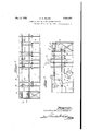
- Figure 1 is a side elevational view of the receiving end of a plating machine.
- Figure 2 is a side elevation of the discharge end of a plating machine.
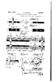
- Figure 3 is an enlarged side elevational view, somewhat diagrammatic in form, of the plating section of a plating-machine.
- Figure 4- is a fragmental end view of F igure 3.
- Figure 5 is a fragmental plan view of one of the plating tank trackways.
- Figure 6 is a side elevational view of the trackways of Figure 5.
- Figure 7 is a top plan view of the plating tank trackways with the sliding bars in initial position.
- Figure 8 is an enlarged end view of a work rod slide showing its association with the trackway and one of the pusher fingers of the slide bars.
- Figure 9 is an end view of Figure 8.
- Figure 10 is a vertical transverse section 'veyor 26 whichdelivers the work through a current regulator for the plating current.
- the work shift mechanism of this inven tion may be used in connection with the chromium plating machine such as that describedin my 'copending application, Serial No. 289,588, filed June 30, 1928.
- the plating machine shown in Figures 1 and..2 comprises vertical structural members and 2 top and bottom membe'rs3 and 4 connected by suitable cross members at intervals.
- Tanks 5, 6, 7 and 8 are supported in the machine and-such tanks are usedfor the preliminary steps in preparing articles'for plating such as rinsing, washing and the like.
- An endless conveyor chain 12 runs over wheels 13, 14, 15,'an'd 16' with the bottom run of the chain near the top of-t-he several tanks.
- the chain is driven'by a motor 17 supported on top of the machine frame, which mo- .tor operates a Reeves drive 18 and which drive in turn operates gear 19 supported in "the frame of the machine, which gear in turn meshes with a bevel gear 20 on shaft 21.
- m-Shaft21 extends substantially the length of the machine and is provided at intervals with beveled gears fordriving the transfer conveyors.
- the transfer conveyors comprise a plurality of endless chains 22 passing over rollers 23'and 24 with the roller 24 in mesh with the 'bevel gear 25 on the shaft 21. .
- All of the transfer "conveyors shown are of this type and are arrangedrto move in the direction indicated by the arrows in the several figures.
- trackways comprising an insulated section an intermediate bus-barsection 31 and another insulated 'section32. The trackways are so arranged thatwhen a work rod is delivered to the plating tank by the transfer v conveyor 26the work rod slides are deposited on the firstinsulated section 30 of the trackway.
- the work .rods 33 have slides 34 secured near the ends of the rods.
- the slides have 'fianges "35 for guiding the same along th trackway's adj acen't'the othertanks of the machine as, well .as the trackways along the plating section.
- the work shift mechanism of this invention comprises a sliding rod 36 arranged one on each side of the main conveyor chains 12.
- the trackways of the plating section are arranged a slight distance above the main conveyor chain 12, so that-this chain will not interfere with the intermittent motion of the work rods through the plating section.
- Figure 7 shows a work rod 33 as delivered to the plating tank trackways by the transfer conveyor 26.
- Stops 40 are provided to prevent swinging .movement of the finger 37 in counter-clockwise direction, as viewed in Figures 3, 8 and 9 of the drawings.
- the length of the slide bars 36 is approxilmately slightly more than half the distance transfer conveyor 26 ready to been'gaged by the front'fingers 37 on theslidebars 36. 1
- The'se'cond position of the rod that is,position B, isthat occupied by the rod when it has been moved into engagement with the -busbar' 31 of the trackway, and wherethe rod remains at rest for a predetermined period of time, as hereinafter'more fully explained.
- Thethird or C position of the rod is the position occupied by the rod after it has'been moved off of the'bus-bar section 31 onto the endinsula'ted section '32 of the trackway in position to be engaged by the transfer conveyor 41 for removal from the tank.
- the slide bars 36 have an undercut slot '42 extending lengthwise of' the bars which undercut portions ride. on an upturned ledge 43 of the frame structure of-the machine. bymeans of the conveyor 12 and the several.
- crank 51 the outer end of which crank is connected by a pitman bar 52 to the lever 44 at 53.
- A; mutilated gear'54 is carried on shaft 55 secured in the framework of the machine and is driven by a gear 56 in mesh with gear 57 carried by the shaft '55.
- the gear 56 is driven by a sprocket 58 by means of a sprocket chain '59 which passes over a second sprocket 60 supported in the framework, which sprocket 60 is'driven by bevel ear 61 on shaft 21".
- the mutilated gear 54 has a portion of its circumference provided with gear teeth 62 which mesh with the teeth on the pinion 49.
- the number of the teeth 62 is such as to impart one complete revolution to the pinion 49 while the teeth are in mesh with the pinion.
- the parts are so arranged that the slide bars 36 complete one cycle of movement, that is, from the position shown in full lines in Figure 3, to the position shown in dotted lines and back to full line position while the teeth 62 of the mutilated gear 54 are in mesh with the pinion 49.
- the slide bars have completed one cycle of movement, the mutilated gear moves out of mesh with the pinion 49, with the result that the bars remain at rest for a period of time until the teeth 62 on the mutilated gear 54 again mesh with the pinion 49.
- a work rod 33 is delivered by the transfer conveyors 26 to the plating tank trackway in the A or first position, that is, with the slides 34 of the work rod resting on the insulated sect-ion 30 of the trackway.
- the teeth 62 of the mutilated gear 54 mesh with the pinion 49, rotating the same, moving the slide bars 36 to the right, as viewed in Fig ure 3 of the drawings, to the dotted line position.
- Such movement will move the work rod from the A position to the 13 position where the slides 34 thereof are in contact with the bus bar 31.
- the slide bars are then returned to initial position and remain at that position until the teeth 62 of the muti lated gear 54 again mesh with the pinion 49.
- an electric current of proper density is sup plied to the bus bar 31 through a conductor 63 which is connected to the armature of a generator.
- the duration of the current supply is limited by a controller such as that shown in Figure 10, so as to cutoff the current before the rod is moved from the B position to the C position.
- the next step is the movement of the slide bars 36 in the neXt cycle wherein the rod in the 13 position is engaged by he fingers 37 at the right hand end of the bars and moved to the C position while at the same time, a rod which has been delivered to the slide bars in the A position is moved into the B position.
- the rod in the C position is then engaged by the transfer conveyor 41 and taken over into the first rinsing tank 10.
- chromium plating may be 3 successfully carried out if an electric ourrent of proper density is supplied without fluctuation and variation to the work rod in the plating or B position.
- control mechanism which I prefer to employ being shown in my copending application Serial No. 289,588, filed June 30, 1928. It consists of a control device 63 supported on the frame of the machine in which is ar ranged a drum 64 on a shaft 65. The drum is driven through a gear train 66 by the main shaft 21.
- the drum 64 has strip conductors 67, certain of which are provided with gaps to break the circuit, as stated in my co-pending application. There is one strip which is continued about the surface of the drum and this is contacted by brush 68 from which a terminal 69 leads to the field circuit of the generator.
- Adjustable brushes 70 are secured to the controller 63 by set screws 71 so as to be moved to vary the gap between the ends of the shorter conductors 67 on the drum.
- the current controller 63 is driven from the main shaft 21 as is also the mutilated gear 5-4 which actuates the slide bars 36.
- the conveyor mechanism for the plating tank, the transfer conveyors including the conveyors 26 and 41, drum controller and the main conveyor chain 12 are all driven from the same main shaft 21 in timed relation so that work rods being fed to the machine at the receiving end move automatically through the tanks ahead of the plating tank 9, and are then moved intermittently through the plating tank 9 in the manner above described for plating purposes.
- Vork rods may be delivered into the plating tank 9 by the transfer conveyor 26 and removed therefrom by the conveyor 41 while the work rod in the B position is in circuit without any plating current passing through any of the articles supported on the rods in the A or C positions.
- a hold-down device for pressing the slides 34 of the work rods against the bus bars 31 of the trackways.
- This hold-down device comprises an arm 72 pivoted at 73 ina cross-head 74 moving in guideways 75 carried on the frame members 76.
- the arm 72 has a weighted end 77 on the opposite side of the pivot 7 3 so arranged to hold the rod 72 at an angle directed towards the oncoming work rod being moved from the A position to the B position.
- the lower end of the arm 72 is forked, having a long prong 78 and a shorter prong 7 9 to straddle the Work rod 33. As the Work rod moves from the B to the C position, the
- a plate 80 is secured to the frame member 7,6 for the purpose of carrying a stop 81 to limit the swinging movement of the arm 72 in clockwisedirection, as viewed in Figure 3.
- Work rod as used in theclaims is used generally and includes not only the rod per se, but-also the pieces or articles to be plated, as well as the means for suspending the same from the rod. The claims are therefore to be construed accordingly.
- An automatic work shift comprising a slide, means for intermittently moving the same through a complete cycle, means on the slide for engaging a Work support in'one directionof movement and for avoiding the support in the opposite direction of'movement, means for moving said slide comprisingarocking lever, a gear connected to said lever, and a continuously moving mutilated gear for imparting intermittent rotation to 40 said first gear.
- An automatic Work shift comprising a slide, a rocker arm connected to said slide, meansconnected to said arm for moving said v slide through a complete cycle, said means being'effective to stay said slide for a predetermined interval at the end of every cycle, a trackway adjacentsaid slide, a work support movable on said trackway, means on said slide for engaging saidwork support in onedirection of'movement of said slide and V for 'avoiding' said work support in the opposite direction of movement, said slide moving means including a gear, a crank on said gear, a pitman connecting said crank and said rocker arm, and a mutilated gear ar- V ranged to work with said first gear and impart one revolution thereto While in mesh, the parts being so arranged that one revolution of said first gear moves said slide 69 through one complete cycle;
Landscapes
- Electroplating Methods And Accessories (AREA)
Description
y 1932- c. G. MILLER 1,856,497
AUTOMATIC WORK SHIFT FOR PLATING MACHINES Original Filed June 30, 1928 I5 Sheets-Sheet l :mvsnZar Constantine CZ Malls r,
May 3, c G MILLER AUTOMATIC WORK SHIFT FOR PLATING MACHINES Original Filed June 30, 1928 3 Sheets-Sheet 2 Cons tantb'ne G. MlZer.
y 1932 c. G. MILLER 1,856,497
AUTOMATIC WORK SHIFT FOR PLATING MACHINES Original Filed June so, 1928 s Sheets-Sheet 3 Patented May 3, 1932 UNHTED STATES PTET OFFICE CONSTANTINE G. MILLER, OF CHICAGO, ILLINOIS, ASSIGN'OR TO THE MEAKER COM- PANY, A CORPORATION OF ILLINOIS AUTOMATIC WORK SHIFT FOR PLATING- MACHINES Application filed June 30, 1928, Serial No. 289,590. Renewed January 14, 1931.
o This invention relates to chromium plating machines and particularly to an automatic work shift for such machines.
I have foundthat articles may be success fully plated with chromium in a machine if the articles in the plating bath are stopped from movement while the electric current is supplied to the articles for plating.
My invention is directed to awork shift 3 mechanism for automatically moving work rods and the supported articles to be plated through a plating bath in step by step movement in combination with a trackway for the plating bath, which trackway has a central bus-bar with insulated end portions.
The work shift of my invention co-operates with the mechanism for delivering work rods to the plating tank and for withdrawing the rods from the tank so that the rods are delivered to the tank, moved into plating position, plated and withdrawn automaticall A i1 object of the invention is to provide an automatic intermittent work shift for plating machines in which a reciprocated push rod is provided for moving work rods through a plating tank in step by step movement and In which a rod remains at rest in the plating tank for a definite period of time. During such time of rest, electric. plating current is supplied to the rod.
Another object of the invention is to provide an automatic work shift for plating machines wherein work rods are moved through a platin tank in step by step movement and brought to rest while in said tank on a busbar, and while at rest, are supplied with an electric current, the current supply and the work shift mechanism being operated in timed relation.
A further object of the invention is to provide an automatic intermittent work shift for the plating'section of the plating machine wherein the work rods are moved intermittently through the plating tank by a rechines in which work rods are shifted automatically through a plating tank in step by step movement and duringsuch movement, a rod is brought to rest on a bus-bar for connection in a plating circuit.
Further, other and additional objects will be apparent from the following description and drawings and appended claims.
T he invention contemplates a slide bar on each side of a plating tank or a slide bar on one side of a plating tank actuated by geared mechanism whereby the bar is moved through one complete cycle and brought to rest for a predetermined period of time, the cycles being repeated intermittently in equal intervals of time.
The invention contemplates further the movement of a work rod through a plating tank by a sliding bar which movement is in three stages or steps, and with the rod remaining at rest in the second step or stage for a predetermined period of time, during which time electric current is supplied to the rod for plating purposes.
One form of the invention is shown in the accompanying drawings and the views thereof are as follows:
Figure 1 is a side elevational view of the receiving end of a plating machine.
Figure 2 is a side elevation of the discharge end of a plating machine.
Figure 3 is an enlarged side elevational view, somewhat diagrammatic in form, of the plating section of a plating-machine.
Figure 4- is a fragmental end view of F igure 3.
Figure 5 is a fragmental plan view of one of the plating tank trackways.
Figure 6 is a side elevational view of the trackways of Figure 5.
Figure 7 is a top plan view of the plating tank trackways with the sliding bars in initial position. I
Figure 8 is an enlarged end view of a work rod slide showing its association with the trackway and one of the pusher fingers of the slide bars.
Figure 9 is an end view of Figure 8.
Figure 10 is a vertical transverse section 'veyor 26 whichdelivers the work through a current regulator for the plating current.
The work shift mechanism of this inven tion may be used in connection with the chromium plating machine such as that describedin my 'copending application, Serial No. 289,588, filed June 30, 1928.
The plating machine shown in Figures 1 and..2 comprises vertical structural members and 2 top and bottom membe'rs3 and 4 connected by suitable cross members at intervals.
v-Th'e plating section'of the machine in-' 'clud'es'a plating tank 9 and'rinsin'g tanks '10 and 11. I, An endless conveyor chain 12 runs over wheels 13, 14, 15,'an'd 16' with the bottom run of the chain near the top of-t-he several tanks.
The chain is driven'by a motor 17 supported on top of the machine frame, which mo- .tor operates a Reeves drive 18 and which drive in turn operates gear 19 supported in "the frame of the machine, which gear in turn meshes with a bevel gear 20 on shaft 21. m-Shaft21 extends substantially the length of the machine and is provided at intervals with beveled gears fordriving the transfer conveyors. p
' The transfer conveyors comprise a plurality of endless chains 22 passing over rollers 23'and 24 with the roller 24 in mesh with the 'bevel gear 25 on the shaft 21. .All of the transfer "conveyors shown are of this type and are arrangedrto move in the direction indicated by the arrows in the several figures. I
The work rods supporting the articles to bep'latedareidelivered to the conveyor chain 12 at the. front end 'ofthe machine and are carried successively through the several tanks transfer conveyors 2-2 to the transfer conrods to the plating tank 9..- i 1 Along each side of the plating tank are trackways comprising an insulated section an intermediate bus-barsection 31 and another insulated 'section32. The trackways are so arranged thatwhen a work rod is delivered to the plating tank by the transfer v conveyor 26the work rod slides are deposited on the firstinsulated section 30 of the trackway.
' The work .rods 33 have slides 34 secured near the ends of the rods. The slideshave 'fianges "35 for guiding the same along th trackway's adj acen't'the othertanks of the machine as, well .as the trackways along the plating section.
The work shift mechanism of this invention comprises a sliding rod 36 arranged one on each side of the main conveyor chains 12. The trackways of the plating section are arranged a slight distance above the main conveyor chain 12, so that-this chain will not interfere with the intermittent motion of the work rods through the plating section.
Figure 7 shows a work rod 33 as delivered to the plating tank trackways by the transfer conveyor 26.
'Theslide bars '36have at each end gravity fingers 37 pivoted at38 with a depending portion 39 of snfficient weight to retain the fingers in the position shownin Figure 8.
The'se'cond position of the rod, that is,position B, isthat occupied by the rod when it has been moved into engagement with the -busbar' 31 of the trackway, and wherethe rod remains at rest for a predetermined period of time, as hereinafter'more fully explained.
Thethird or C position of the rod is the position occupied by the rod after it has'been moved off of the'bus-bar section 31 onto the endinsula'ted section '32 of the trackway in position to be engaged by the transfer conveyor 41 for removal from the tank.
The slide bars 36 have an undercut slot '42 extending lengthwise of' the bars which undercut portions ride. on an upturned ledge 43 of the frame structure of-the machine. bymeans of the conveyor 12 and the several.
the frame structure of the machine, and has fastened thereto a crank 51, the outer end of which crank is connected by a pitman bar 52 to the lever 44 at 53. i
. A; mutilated gear'54 is carried on shaft 55 secured in the framework of the machine and is driven by a gear 56 in mesh with gear 57 carried by the shaft '55. I j
The gear 56 is driven by a sprocket 58 by means of a sprocket chain '59 which passes over a second sprocket 60 supported in the framework, which sprocket 60 is'driven by bevel ear 61 on shaft 21".
The mutilated gear 54 has a portion of its circumference provided with gear teeth 62 which mesh with the teeth on the pinion 49. The number of the teeth 62 is such as to impart one complete revolution to the pinion 49 while the teeth are in mesh with the pinion.
The parts are so arranged that the slide bars 36 complete one cycle of movement, that is, from the position shown in full lines in Figure 3, to the position shown in dotted lines and back to full line position while the teeth 62 of the mutilated gear 54 are in mesh with the pinion 49. When the slide bars have completed one cycle of movement, the mutilated gear moves out of mesh with the pinion 49, with the result that the bars remain at rest for a period of time until the teeth 62 on the mutilated gear 54 again mesh with the pinion 49.
The operation of the device is as follows:
A work rod 33 is delivered by the transfer conveyors 26 to the plating tank trackway in the A or first position, that is, with the slides 34 of the work rod resting on the insulated sect-ion 30 of the trackway. As soon as the rod has been delivered in the A position, the teeth 62 of the mutilated gear 54 mesh with the pinion 49, rotating the same, moving the slide bars 36 to the right, as viewed in Fig ure 3 of the drawings, to the dotted line position. Such movement will move the work rod from the A position to the 13 position where the slides 34 thereof are in contact with the bus bar 31. The slide bars are then returned to initial position and remain at that position until the teeth 62 of the muti lated gear 54 again mesh with the pinion 49. /Vhile the work rod is in the B position, an electric current of proper density is sup plied to the bus bar 31 through a conductor 63 which is connected to the armature of a generator.
The duration of the current supply is limited by a controller such as that shown in Figure 10, so as to cutoff the current before the rod is moved from the B position to the C position.
The next step is the movement of the slide bars 36 in the neXt cycle wherein the rod in the 13 position is engaged by he fingers 37 at the right hand end of the bars and moved to the C position while at the same time, a rod which has been delivered to the slide bars in the A position is moved into the B position.
The rod in the C position is then engaged by the transfer conveyor 41 and taken over into the first rinsing tank 10.
The slide bars 36 returning to initial position, will bring the fingers 37 against the fronts of the several rods, whereupon the fingers swinging onthe pivot 38 will avoid the rods in this direction of movement.
I have found chromium plating may be 3 successfully carried out if an electric ourrent of proper density is supplied without fluctuation and variation to the work rod in the plating or B position.
I prefer to control the field current of the generator rather than the armature current, the control mechanism which I prefer to employ being shown in my copending application Serial No. 289,588, filed June 30, 1928. It consists of a control device 63 supported on the frame of the machine in which is ar ranged a drum 64 on a shaft 65. The drum is driven through a gear train 66 by the main shaft 21.
The drum 64 has strip conductors 67, certain of which are provided with gaps to break the circuit, as stated in my co-pending application. There is one strip which is continued about the surface of the drum and this is contacted by brush 68 from which a terminal 69 leads to the field circuit of the generator.
The current controller 63 is driven from the main shaft 21 as is also the mutilated gear 5-4 which actuates the slide bars 36.
It will be observed, therefore, that the conveyor mechanism for the plating tank, the transfer conveyors including the conveyors 26 and 41, drum controller and the main conveyor chain 12 are all driven from the same main shaft 21 in timed relation so that work rods being fed to the machine at the receiving end move automatically through the tanks ahead of the plating tank 9, and are then moved intermittently through the plating tank 9 in the manner above described for plating purposes.
The provision of the plating tank trackway as described makes it possible for the plating of but one work rod at a time, that is, the one in the second or B position. Vork rods may be delivered into the plating tank 9 by the transfer conveyor 26 and removed therefrom by the conveyor 41 while the work rod in the B position is in circuit without any plating current passing through any of the articles supported on the rods in the A or C positions.
t will be observed that I have provided a work shift mechanism for plating tanks which is positive in operation and which moves the work rods intermittently through the plating tank.
I have provided. a hold-down device for pressing the slides 34 of the work rods against the bus bars 31 of the trackways.
This hold-down device comprises an arm 72 pivoted at 73 ina cross-head 74 moving in guideways 75 carried on the frame members 76.
The arm 72 has a weighted end 77 on the opposite side of the pivot 7 3 so arranged to hold the rod 72 at an angle directed towards the oncoming work rod being moved from the A position to the B position. v
The lower end of the arm 72 is forked, having a long prong 78 and a shorter prong 7 9 to straddle the Work rod 33. As the Work rod moves from the B to the C position, the
arm swings with it until the prong 79 moves over the work rod, whereupon the rod swings back into inclined position in the opposite direction ready to engage the next Work rod.
A plate 80 is secured to the frame member 7,6 for the purpose of carrying a stop 81 to limit the swinging movement of the arm 72 in clockwisedirection, as viewed in Figure 3. V The term Work rod as used in theclaims is used generally and includes not only the rod per se, but-also the pieces or articles to be plated, as well as the means for suspending the same from the rod. The claims are therefore to be construed accordingly.
While I have described more or less precisely the details of construction of my invention, yet I do not wish to be understood as limiting myself thereto, as I am aware that changes may be made in the arrangement and proportion of parts and that equivalents may be substituted, all without departing from the spirit and scope of my invention. I claim as my invention: 1. An automatic work shift comprising a slide, means for intermittently moving the same through a complete cycle, means on the slide for engaging a Work support in'one directionof movement and for avoiding the support in the opposite direction of'movement, means for moving said slide comprisingarocking lever, a gear connected to said lever, and a continuously moving mutilated gear for imparting intermittent rotation to 40 said first gear. 7
2. An automatic Work shift comprising a slide, a rocker arm connected to said slide, meansconnected to said arm for moving said v slide through a complete cycle, said means being'effective to stay said slide for a predetermined interval at the end of every cycle, a trackway adjacentsaid slide, a work support movable on said trackway, means on said slide for engaging saidwork support in onedirection of'movement of said slide and V for 'avoiding' said work support in the opposite direction of movement, said slide moving means including a gear, a crank on said gear, a pitman connecting said crank and said rocker arm, and a mutilated gear ar- V ranged to work with said first gear and impart one revolution thereto While in mesh, the parts being so arranged that one revolution of said first gear moves said slide 69 through one complete cycle; I In testimony whereof I have hereunto subscribed my name at Chicago, Cook County,
Illinois. 4 I CONSTANTINE G. MILLER.
Priority Applications (1)
| Application Number | Priority Date | Filing Date | Title |
|---|---|---|---|
| US289590A US1856497A (en) | 1928-06-30 | 1928-06-30 | Automatic work shift for plating machines |
Applications Claiming Priority (1)
| Application Number | Priority Date | Filing Date | Title |
|---|---|---|---|
| US289590A US1856497A (en) | 1928-06-30 | 1928-06-30 | Automatic work shift for plating machines |
Publications (1)
| Publication Number | Publication Date |
|---|---|
| US1856497A true US1856497A (en) | 1932-05-03 |
Family
ID=23112193
Family Applications (1)
| Application Number | Title | Priority Date | Filing Date |
|---|---|---|---|
| US289590A Expired - Lifetime US1856497A (en) | 1928-06-30 | 1928-06-30 | Automatic work shift for plating machines |
Country Status (1)
| Country | Link |
|---|---|
| US (1) | US1856497A (en) |
-
1928
- 1928-06-30 US US289590A patent/US1856497A/en not_active Expired - Lifetime
Similar Documents
| Publication | Publication Date | Title |
|---|---|---|
| SU441714A1 (en) | Feed method of spinning machine | |
| US2299618A (en) | Automatic conveying and elevating machine | |
| US3722662A (en) | Successive transfer apparatus for surface treatment of elongate articles | |
| US1856497A (en) | Automatic work shift for plating machines | |
| US2341606A (en) | Electroprocessing machine | |
| US1594326A (en) | Blank-reversing device for drawing presses | |
| US3288976A (en) | Apparatus for welding wires on condenser coils | |
| US2175788A (en) | Electroprocessing machine | |
| US3340850A (en) | Apparatus for continuously conveying tubes through a hot galvanising bath | |
| US2902181A (en) | Apparatus for performing treatment operations on workpieces | |
| US1965745A (en) | Off-bearing machine | |
| US3099348A (en) | Apparatus for advancing like elongated finishing bars | |
| US1764153A (en) | Leer feeder | |
| US1959799A (en) | Method and apparatus for treating material | |
| US1946360A (en) | Dipping machine | |
| US1809136A (en) | Plating machine automatic work shift | |
| DE1276489B (en) | Device for removing bottles or the like from bottle washing machines | |
| US2013032A (en) | Device for feeding or withdrawing bottles for bottle rinsing machines | |
| US2612984A (en) | Shingle conveyer | |
| US2802559A (en) | Conveying mechanism | |
| US3125134A (en) | Machine for | |
| US2823787A (en) | Apparatus for handling shell casings and the like | |
| US1418117A (en) | Feeding device for slitters | |
| US2923304A (en) | Apparatus for treating edge portions of can body blanks | |
| US1809138A (en) | Automatic chromium plating machine |