US1856496A - Clock with ringing mechanism - Google Patents
Clock with ringing mechanism Download PDFInfo
- Publication number
- US1856496A US1856496A US365382A US36538229A US1856496A US 1856496 A US1856496 A US 1856496A US 365382 A US365382 A US 365382A US 36538229 A US36538229 A US 36538229A US 1856496 A US1856496 A US 1856496A
- Authority
- US
- United States
- Prior art keywords
- clock
- sprocket
- secured
- chain
- pins
- Prior art date
- Legal status (The legal status is an assumption and is not a legal conclusion. Google has not performed a legal analysis and makes no representation as to the accuracy of the status listed.)
- Expired - Lifetime
Links
- 230000007246 mechanism Effects 0.000 title description 17
- 239000004020 conductor Substances 0.000 description 10
- 230000027455 binding Effects 0.000 description 6
- 238000009739 binding Methods 0.000 description 6
- 239000000835 fiber Substances 0.000 description 3
- 238000010516 chain-walking reaction Methods 0.000 description 2
- 238000010586 diagram Methods 0.000 description 2
- 239000011810 insulating material Substances 0.000 description 1
- 239000000463 material Substances 0.000 description 1
- 239000002184 metal Substances 0.000 description 1
Images

Classifications
-
- G—PHYSICS
- G04—HOROLOGY
- G04C—ELECTROMECHANICAL CLOCKS OR WATCHES
- G04C21/00—Producing acoustic time signals by electrical means
- G04C21/16—Producing acoustic time signals by electrical means producing the signals at adjustable fixed times
- G04C21/30—Producing acoustic time signals by electrical means producing the signals at adjustable fixed times with provision for a number of operations at different times, e.g. ringing the bells in a school
Definitions
- This invention relates to a program clock mechanism.
- Program clocks are now used in schools, factories and. other places where it is desired to have signals sounded or given at certain intervals. It is desirable in such a mechanism to have a structure that is easily accessible in relation to a standard clock, one which is simple and requires little attention. It is an object of this invention to provide a very simple and efficient program clock mechanism which is easily installed in connection with a standard clock and is in a very accessible position.
- It is a further object of the invention to provide a program clock mechanism comprisin a sprocket Wheel preferably driven from the minute hand spindle of the clock, a. flexible member running over said sprocket and carrying spaced contact members which are engaged by a contact arm to close an electrical circuit.
- F ig. 2 is a horizontal section taken substantially on line 22 of Fig. 1 as indicated by the arrows;
- Fig. 3 is a vertical section taken on line 33 of Fig. l, as indicated by the arrows;
- Fig. 4 is a wiring diagram showing parts of the apparatus
- Fig. 5 is a partial view similar to Fig. 1, shown on an enlarged scale, and
- Fig. 6 is a plan view of the chain and contact members used.
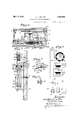
- a clock is shown mounted in a casing 10 of box-like form, which clock is of the standard pendulum type.
- Casing 10 has a rear side or panel 10a and the same is shown as having a door 10?) at its front mounted on hinges 11 and adapted to be held closed by a hook and eyelet 12.
- the usual clock mechanism is carried in a frame 13, of which mechanism it will only be necessary to consider the minute hand spindle 14.
- the hour hand 15 is shown, as is also the minute hand 16.
- a door 17, comprising a shallow casing is mounted in the rear of the clock on hinges 1S and adapted to be held in closed position by a hook and eyelet 19.
- a plate is secured by suitable small screws 21 to the rear of panel 10a, which plate preferably will be made of some nonin'f'lammable material of an insulating type, such as hard fibre.
- the minute hand spindle. 14 extends through an aperture in panel 10a and has, in the rear of plate 20, a sprocket wheel'22 rigidly secured thereto by a set screw 23. While this sprocket wheel could be varied in size and have difi'erent numbers of teeth thereon, in the embodiment of the invention illustrated, said wheel is shown as having 2d teeth.
- a flexible member 24, which in the embodiment of the invention illustrated is shown as a flat-linked chain is provided and runs over sprocket 22, the links of said chain fitting over the teeth of said sprocket.
- the teeth on sprocket 22 are spaced so as to engage every other link of chain 24, as clearly shown in Fig. 5.
- a plurality of other sprocket wheels 25 are journaled on pins 26 mounted in plates 27 secured to rear panel a by small screws, said sprockets being substantially in the same plane as sprocket 22. lVhile the disposition of sprockets 25 could be varied, in the embodiment of the invention illustrated they are shown as placed substantially at the upper and lower corners of panel 10a.
- the sprockets 25 are held on the pins 26 by the cotter pins 28.
- the chain 24 is closed or end less and runs continuously over the sprockets 22 and 25.
- the chain 24 has mounted therein at suitable intervals contact, members 29.
- the sprocket 22 as shown in Fig. 3 comprises a central toothed metallic disk 22a, to which are attached the spaced supporting disks 225 having cylindrical peripheries the same being secured to disk 22a by a plurality of small headed and nutted bolts 220 which pass through spacing thimbles 22d at each side of disk 22a.
- T he outer end of the minute hand spindle 14 is journalcd and supported inangular bracket 30 secured at its lower end to panel 100.
- a block 31 is secured to panel 10a above plate 20 and has secured thereto an insulating block 32.
- Block 32 has secured to each side thereof small metal plates 33 and stop arms or brackets 34 are secured to the plates 33 by small headed screws 35 having washers 36 disposed between their heads and the brackets 34. Screws 35 pass through elongated vertically disposed slots 34a in brackets 34 so that the same may be adjusted vertically and held in different vertical positions.
- Brackets 34 have their lower ends twisted at a right angle and curved laterally to form a lip 34?).
- Brackets 37 are secured at each side of block 32 adjacent one end thereof and have the lower ends outturned, said ends having secured thereto one end respectively of spring arms 38.
- the other end of said arms have secured thereto a small U shaped clip or bracket 39 having a depending portion 39a forming a contact member. These portions 39a. are disposed directly above the axis of sprocket 22 and are attached to be engaged by the contact members or pins 29 as they move over the sprocket.
- Clip 39 has secured between its sides and end by a rivet 40 a fibre or insulating segment 41 having a lip 41a at its outer end adapted to be engaged by the curved lip 34?) at the bottom of the brackets 34, said lip forming a stop for member 41 and arm 38. It will be understood that the arms 38 are separate and the contact members 39a separately engage the contact members or pins 29.
- the brackets 37 will have suitable electrical conductors 42 respectively connected thereto which will extend to binding posts 43, shown as mounted on top of the clock.
- means for opening the circuit which operates the signals during the night time.
- This comprises a shaft 44 journaled in a bracket 45 extending from one side of the clock frame 13 and supported on a block 100 secured to the inner side of panel 10a.
- This shaft 44 has secured to its front end a ratchet-- toothed disk 46.
- An arm 47 is provided having a hub embracing the hour hand sleeve and secured thereto by a small set screw 48, said arm having at its other end a laterally projecting pin 47a extending into line with the teeth of ratchet 46.
- Shaft 44 extends through an aperture in panel 10a and through a plate 49 secured to the rear of panel 10a in which plate it is journaled.
- a disk 50 comprising one member of a switch is secured to the outer end of shaft 44.
- Disk 50 as shown in Fig. 4 is made of fibre or other suitable insulating material at its outer portion and has secured to its sides and extending over its edge spaced metallic clips 51, the same being secured to the disk by small screws extending therethrough and into the central metallic part of the disk. As shown in Fig. 4, segments 51 are thus in electrical communication with shaft 44. Segments 51 are made flat at their outer sides or with their surfaces in a plane.
- An arm 52 has its lower end bent into triangular shape to form a point or ridge adapted to engage members 51, said arm having a flange 52a at its upper end secured by suitable screws to the rear of panel 10a.
- a conductor 53 is secured to arm 52 and extends to a suitable binding post 54, shown as mounted on top of the clock casing 10.
- a plate 10d is secured to the door or casing 17 having holes 106 therethrongh with slots projecting upwardly therefrom and forms a supporting plate for the clock whereby it may be hung upon suitable screws or other supporting means.
- a wiring diagram for the mechanism comprising a battery 55 having a conductor 56 extending therefrom to the binding post 54, another conductor 57 extending from the other side of the battery to a signal device such as an alarm bell 58.
- a conductor 59 extends from the other terminal of hell 58 to one of the binding posts 43.
- a conductor 60 extends from conductor 57 to a second device shown as frame 13 which is in electrical connection with spindle 14, said bracket also being electrically connected to shaft 44.
- the minute hand spindle 14 of the clock will be driven by the clock mechanism in the usual manner and this will turn sprocket wheel 22.
- sw-1tch arm 52 15 in engagement with one *of the metallic segments or contact members 51.
- Arms 38 normally spring downward and are held in a certain position by the lips 41a engaging the lips 34?).
- As many pins 29 may be placed in the chain as desired and if a pin is placed in every other link, one of the pins will pass under the contact means 39a every two and one-half minutes.
- the pin is carried over the sprocket 22 it rides on the edges of the disks 22b and as stated, comes under the contact means 39a.
- the pins are thus firmly supported and a firm and positive contact is secured.
- the pin riding under the contact raises arms 38 slightly as shown in Figs. 1 and 5.
- the circuit is closed when members 39a and 29 engage, as illustrated in Fig. 4 and the bells 58 and 61 will be sounded. It may be pointed out that the circuit for ringing the bells will extend from battery 55 through conductors 57 and 60 to the bells 58 and 61 and from the bells to the bind ing post 43. From the binding post 43 the circuit extends through conductors 42 to arms 38 and to contact means 39a.
- the contact means 89a engages the pins or contact members 29 which engage the chain 24 which is engaged by the teeth on the central metallic portion 22a of sprocket 22.
- the arm 47 or the hour hand sleeve makes a revolution every twelve hours.
- This arm is usually arranged to engage the ratchet 46 at six a. m. and sixp. m. Said arm moves the ratchet wheel 46 the distance of one tooth and the disk 50 will be turned at six p. m. to place switch arm 52 in contact with the portion of the disk between the contact members
- the circuit will thus be opened and remain open until six a. in, when the ratchet disk 46 will again be operated and switch arm 52 brought into engagement with one of the contact segments 51 if present and the device will then be in a position to operate for the next twelve hours.
- switch disk 50 is shown as having five members 51 with two missing. lVith this arrangement the circuit would be open from Friday 6 p. 111. until Monday at 6 a. m., an arrangement suitable for many schools.
- hat is claimed is 1.
- a clock including an hour hand and a minute hand, of a program clock structure including a rotatable means fixed upon the spindle of the minute hand of said clock, a flexible member passing over said rotatable means and driven thereby, two sets of contact members carried by said flexible member and projecting at the sides thereof respectively, and a contact arm carrying two contact members positioned to be engaged respectively by-said contact members of said sets for controlling two programs.
- a program clock having in combination with the minute hand spindle of a clock, a support, a sprocket wheel rigidly secured to said spindle, a plurality of sprockets rotatably mounted on said support and dis osed substantially in the same plane as sai first mentioned sprocket, an endless chain moving over said sprockets, and driven by said first mentioned sprocket, two sets of contact members carried by said chain and projecting respectively at the sides thereof, contact members disposed above said first mentioned sprocket for engagement respectively with said first mentioned contact members, means urging said latter members toward said sprocket, means for holding said members thereto in different positions, said latter members being arranged to be engaged respectively by said contact members on said chain to close an electrical circuit whereby two programs can be signalled.
- a program clock structure having in combination with a clock casing having a panel at its rear side, a sprocket mounted on the rear side of said panel and secured to the minute hand spindle of said clock, a plurality of spaced sprockets mounted.
- a program clock structure having in combination with the minute hand spindle of a clock, a sprocket rigidly secured to said spindle, comprising a central metallic toothed disk secured to said spindle, annular disks supporting contact pins disposed at each side of said first mentioned disk and secured thereto having circular peripheries of approximately the same diameter as the diameter of said sprocket, a chain passing over and driven by said sprocket, contact pins carried by said chain and projecting at the sides thereof adapted to ride on the periphery of said disks as said chain passes over said sprocket and be supported thereby and contact means disposed adjacent said sprocket and resiliently urged toward the same, positioned to be engaged by said pins as said pins pass over said sprocket.
- a program clock structure having in combinationwith the minute hand spindle of a clock, a sprocket rigidly secured to said spindle comprising a central metallic toothed disk secured to said spindle, an annular disk secured at one side of said central disk and spaced therefrom, a chain running over said sprocket and driven thereby, pins secured to said chain and projecting at one side thereof, said pins riding on the periphery of said insulating disk and supported thereby, as said chain passes over said sprocket, a contact means disposed adjacent said sprocket and resiliently urged toward the same, positioned to engage the projecting portions of said pins as said chain'passes over said sprocket.
Landscapes
- Physics & Mathematics (AREA)
- General Physics & Mathematics (AREA)
- Electric Clocks (AREA)
- Electromechanical Clocks (AREA)
Description
May 3, 1932.
A H. MlLLER CLOCK WITH RINGING MECHANISM Filed May -23 2 Sheets-Sheet l y 1932- A. H. MILLER 1,856,496
CLOCK WITH RINGING MECHANISM Filed May 23, 1929 2 Sheets-Sheet 2.
Patented May 3, 1932 UNITED STATES PATENT OFFICE CLOCK WITH RING-ING MECHANISM Application filed May 23, 1929. Serial No. 365,382.
This invention relates to a program clock mechanism. Program clocks are now used in schools, factories and. other places where it is desired to have signals sounded or given at certain intervals. It is desirable in such a mechanism to have a structure that is easily accessible in relation to a standard clock, one which is simple and requires little attention. It is an object of this invention to provide a very simple and efficient program clock mechanism which is easily installed in connection with a standard clock and is in a very accessible position.
It is a further object of the invention to provide a program clock mechanism comprisin a sprocket Wheel preferably driven from the minute hand spindle of the clock, a. flexible member running over said sprocket and carrying spaced contact members which are engaged by a contact arm to close an electrical circuit.
It is more specifically an object of the invention to provide a program clock structure mounted on a panel in the rear of the f clock having a sprocket Wheel secured to the minute hand spindle, a plurality of other sprocket wheels mounted on said panel substantially in the same plane as said first mentioned sprocket wheel, a chain running over said sprocket wheels and driven by said first mentioned wheel, said chain having contact members thereon, and one or more contact arms adapted to engage said contact members to close the electrical circuits which operate the signals.
These and other objects and advantages of the invention will be fully set forth in the following description made in connection with the accompanying drawings, in which like reference characters refer to similar parts throughout the several views, and in which r Fig- 1 is a view in front elevation of the mechanismshowing the same mounted on a panel in the rear of a clock;
F ig. 2 is a horizontal section taken substantially on line 22 of Fig. 1 as indicated by the arrows;
Fig. 3 is a vertical section taken on line 33 of Fig. l, as indicated by the arrows;
Fig. 4 is a wiring diagram showing parts of the apparatus;
Fig. 5 is a partial view similar to Fig. 1, shown on an enlarged scale, and
Fig. 6 is a plan view of the chain and contact members used.
Referring to the drawings, a clock is shown mounted in a casing 10 of box-like form, which clock is of the standard pendulum type. Casing 10 has a rear side or panel 10a and the same is shown as having a door 10?) at its front mounted on hinges 11 and adapted to be held closed by a hook and eyelet 12. The usual clock mechanism is carried in a frame 13, of which mechanism it will only be necessary to consider the minute hand spindle 14. The hour hand 15 is shown, as is also the minute hand 16. A door 17, comprising a shallow casing is mounted in the rear of the clock on hinges 1S and adapted to be held in closed position by a hook and eyelet 19. A plate is secured by suitable small screws 21 to the rear of panel 10a, which plate preferably will be made of some nonin'f'lammable material of an insulating type, such as hard fibre. The minute hand spindle. 14: extends through an aperture in panel 10a and has, in the rear of plate 20, a sprocket wheel'22 rigidly secured thereto by a set screw 23. While this sprocket wheel could be varied in size and have difi'erent numbers of teeth thereon, in the embodiment of the invention illustrated, said wheel is shown as having 2d teeth. A flexible member 24, which in the embodiment of the invention illustrated is shown as a flat-linked chain is provided and runs over sprocket 22, the links of said chain fitting over the teeth of said sprocket. The teeth on sprocket 22 are spaced so as to engage every other link of chain 24, as clearly shown in Fig. 5. A plurality of other sprocket wheels 25 are journaled on pins 26 mounted in plates 27 secured to rear panel a by small screws, said sprockets being substantially in the same plane as sprocket 22. lVhile the disposition of sprockets 25 could be varied, in the embodiment of the invention illustrated they are shown as placed substantially at the upper and lower corners of panel 10a. The sprockets 25 are held on the pins 26 by the cotter pins 28. The chain 24 is closed or end less and runs continuously over the sprockets 22 and 25. The chain 24 has mounted therein at suitable intervals contact, members 29. While the form of these members may be varied, in the embodimentof the invention illustrated they are shown as small cylindrical pins having spaced reduced portions disposed in the eyelets formed by the links of chain 24. The sprocket 22 as shown in Fig. 3 comprises a central toothed metallic disk 22a, to which are attached the spaced supporting disks 225 having cylindrical peripheries the same being secured to disk 22a by a plurality of small headed and nutted bolts 220 which pass through spacing thimbles 22d at each side of disk 22a. T he outer end of the minute hand spindle 14 is journalcd and supported inangular bracket 30 secured at its lower end to panel 100..
A block 31 is secured to panel 10a above plate 20 and has secured thereto an insulating block 32. Block 32 has secured to each side thereof small metal plates 33 and stop arms or brackets 34 are secured to the plates 33 by small headed screws 35 having washers 36 disposed between their heads and the brackets 34. Screws 35 pass through elongated vertically disposed slots 34a in brackets 34 so that the same may be adjusted vertically and held in different vertical positions. Brackets 34 have their lower ends twisted at a right angle and curved laterally to form a lip 34?). Brackets 37 are secured at each side of block 32 adjacent one end thereof and have the lower ends outturned, said ends having secured thereto one end respectively of spring arms 38. The other end of said arms have secured thereto a small U shaped clip or bracket 39 having a depending portion 39a forming a contact member. These portions 39a. are disposed directly above the axis of sprocket 22 and are attached to be engaged by the contact members or pins 29 as they move over the sprocket. Clip 39 has secured between its sides and end by a rivet 40 a fibre or insulating segment 41 having a lip 41a at its outer end adapted to be engaged by the curved lip 34?) at the bottom of the brackets 34, said lip forming a stop for member 41 and arm 38. It will be understood that the arms 38 are separate and the contact members 39a separately engage the contact members or pins 29. The brackets 37 will have suitable electrical conductors 42 respectively connected thereto which will extend to binding posts 43, shown as mounted on top of the clock.
Most of the program clocks are used where a program of signals is only desired during the day time. In the present structure means is provided for opening the circuit which operates the signals during the night time. This comprises a shaft 44 journaled in a bracket 45 extending from one side of the clock frame 13 and supported on a block 100 secured to the inner side of panel 10a. This shaft 44 has secured to its front end a ratchet-- toothed disk 46. An arm 47 is provided having a hub embracing the hour hand sleeve and secured thereto by a small set screw 48, said arm having at its other end a laterally projecting pin 47a extending into line with the teeth of ratchet 46. Shaft 44 extends through an aperture in panel 10a and through a plate 49 secured to the rear of panel 10a in which plate it is journaled. A disk 50 comprising one member of a switch is secured to the outer end of shaft 44. Disk 50 as shown in Fig. 4 is made of fibre or other suitable insulating material at its outer portion and has secured to its sides and extending over its edge spaced metallic clips 51, the same being secured to the disk by small screws extending therethrough and into the central metallic part of the disk. As shown in Fig. 4, segments 51 are thus in electrical communication with shaft 44. Segments 51 are made flat at their outer sides or with their surfaces in a plane. An arm 52 has its lower end bent into triangular shape to form a point or ridge adapted to engage members 51, said arm having a flange 52a at its upper end secured by suitable screws to the rear of panel 10a. A conductor 53 is secured to arm 52 and extends to a suitable binding post 54, shown as mounted on top of the clock casing 10. A plate 10d is secured to the door or casing 17 having holes 106 therethrongh with slots projecting upwardly therefrom and forms a supporting plate for the clock whereby it may be hung upon suitable screws or other supporting means.
In Fig. 4 a wiring diagram for the mechanism is shown comprising a battery 55 having a conductor 56 extending therefrom to the binding post 54, another conductor 57 extending from the other side of the battery to a signal device such as an alarm bell 58. A conductor 59 extends from the other terminal of hell 58 to one of the binding posts 43. A conductor 60 extends from conductor 57 to a second device shown as frame 13 which is in electrical connection with spindle 14, said bracket also being electrically connected to shaft 44.
In operation the minute hand spindle 14 of the clock will be driven by the clock mechanism in the usual manner and this will turn sprocket wheel 22. Assuming it to be day t11ne, sw-1tch arm 52 15 in engagement with one *of the metallic segments or contact members 51. Arms 38 normally spring downward and are held in a certain position by the lips 41a engaging the lips 34?). As many pins 29 may be placed in the chain as desired and if a pin is placed in every other link, one of the pins will pass under the contact means 39a every two and one-half minutes. As the pin is carried over the sprocket 22 it rides on the edges of the disks 22b and as stated, comes under the contact means 39a. The pins are thus firmly supported and a firm and positive contact is secured. The pin riding under the contact raises arms 38 slightly as shown in Figs. 1 and 5. The circuit is closed when members 39a and 29 engage, as illustrated in Fig. 4 and the bells 58 and 61 will be sounded. It may be pointed out that the circuit for ringing the bells will extend from battery 55 through conductors 57 and 60 to the bells 58 and 61 and from the bells to the bind ing post 43. From the binding post 43 the circuit extends through conductors 42 to arms 38 and to contact means 39a. The contact means 89a engages the pins or contact members 29 which engage the chain 24 which is engaged by the teeth on the central metallic portion 22a of sprocket 22. 'The circuit thus extends through said portion 22a to shaft 14, thence into the clock frame or mechanism 13 to bracket 45, through said bracket to shaft 44, from shaft 44 through disk 50 and contact members 51 to switch arm 52. From switch arm 52 the circuit passes through conductors 53 and 56 to the other side of battery 55. The members 51 are made fiat at their outer sides so that they will tend to remain in position with switch arm 52 engaging the central portion thereof. It will be seen that the mecha nism described is arranged for a double program, two sets of bells being controlled. It is obvious that the pins 29 could be made so as to project at only one side of chain 4 and one arm 88, with its attendant mechanism be used so that a single program would be provided. Likewise, more chains 24 and contact means could be provided to control more than two programs.
The arm 47 or the hour hand sleeve makes a revolution every twelve hours. This arm is usually arranged to engage the ratchet 46 at six a. m. and sixp. m. Said arm moves the ratchet wheel 46 the distance of one tooth and the disk 50 will be turned at six p. m. to place switch arm 52 in contact with the portion of the disk between the contact members The circuit will thus be opened and remain open until six a. in, when the ratchet disk 46 will again be operated and switch arm 52 brought into engagement with one of the contact segments 51 if present and the device will then be in a position to operate for the next twelve hours. In Fig. 4 switch disk 50 is shown as having five members 51 with two missing. lVith this arrangement the circuit would be open from Friday 6 p. 111. until Monday at 6 a. m., an arrangement suitable for many schools.
From the above description it is seen that applicant has provided a very simple and yet very efiicient structure for program ringing by means of a clock. The device iseasily attached to a standard clock and comprises relatively few parts. The mechanism is very accessible, it merely being necessary to open the hook fastener 19 and swing the clock forward about the hinges 18. The mechanism is then exposed. The device has been amply demonstrated in actual practice and found to be very successful and eflicient.
It will, of course, be understood that vari- T ous changes may be made in the form, details, proportions and arrangement of the parts, without departing from the scope of applicants invention, which, generally stated, consists in a device capable of carrying out the objects above set forth, in the novel parts and combinations of parts disclosed and defined in the appended claims.
hat is claimed is 1. The combination with a clock including an hour hand and a minute hand, of a program clock structure including a rotatable means fixed upon the spindle of the minute hand of said clock, a flexible member passing over said rotatable means and driven thereby, two sets of contact members carried by said flexible member and projecting at the sides thereof respectively, and a contact arm carrying two contact members positioned to be engaged respectively by-said contact members of said sets for controlling two programs.
2. A program clock having in combination with the minute hand spindle of a clock, a support, a sprocket wheel rigidly secured to said spindle, a plurality of sprockets rotatably mounted on said support and dis osed substantially in the same plane as sai first mentioned sprocket, an endless chain moving over said sprockets, and driven by said first mentioned sprocket, two sets of contact members carried by said chain and projecting respectively at the sides thereof, contact members disposed above said first mentioned sprocket for engagement respectively with said first mentioned contact members, means urging said latter members toward said sprocket, means for holding said members thereto in different positions, said latter members being arranged to be engaged respectively by said contact members on said chain to close an electrical circuit whereby two programs can be signalled.
3. A program clock structure having in combination with a clock casing having a panel at its rear side, a sprocket mounted on the rear side of said panel and secured to the minute hand spindle of said clock, a plurality of spaced sprockets mounted. on said panel for free rotation, an endless chain passing over all of said sprockets and driven by said first mentioned sprocket, two sets of pins secured to said chain and projecting laterally therefrom respectively adapted to pass between the teeth of said first mentioned sprocket, a resilient arm mounted adjacent said sprocket, two contact means carried by said arm and resiliently urged toward said sprocket in position to be engaged by said pins of each of said sets as they pass over said sprocket, and an electrical circuit adapted to be closed by engagement of said pins and contact means whereby two programs can be signalled by said sets of pins.
4. A program clock structure having in combination with the minute hand spindle of a clock, a sprocket rigidly secured to said spindle, comprising a central metallic toothed disk secured to said spindle, annular disks supporting contact pins disposed at each side of said first mentioned disk and secured thereto having circular peripheries of approximately the same diameter as the diameter of said sprocket, a chain passing over and driven by said sprocket, contact pins carried by said chain and projecting at the sides thereof adapted to ride on the periphery of said disks as said chain passes over said sprocket and be supported thereby and contact means disposed adjacent said sprocket and resiliently urged toward the same, positioned to be engaged by said pins as said pins pass over said sprocket.
5. A program clock structure having in combinationwith the minute hand spindle of a clock, a sprocket rigidly secured to said spindle comprising a central metallic toothed disk secured to said spindle, an annular disk secured at one side of said central disk and spaced therefrom, a chain running over said sprocket and driven thereby, pins secured to said chain and projecting at one side thereof, said pins riding on the periphery of said insulating disk and supported thereby, as said chain passes over said sprocket, a contact means disposed adjacent said sprocket and resiliently urged toward the same, positioned to engage the projecting portions of said pins as said chain'passes over said sprocket.
6. The combination with a clock including an hour hand, a minute hand and a minute hand spindle, of a sprocket wheel rigidly secured to said minute hand spindle, resilient arms extending substantially tangentially of said sprocket, a member carried by each arm
Priority Applications (1)
| Application Number | Priority Date | Filing Date | Title |
|---|---|---|---|
| US365382A US1856496A (en) | 1929-05-23 | 1929-05-23 | Clock with ringing mechanism |
Applications Claiming Priority (1)
| Application Number | Priority Date | Filing Date | Title |
|---|---|---|---|
| US365382A US1856496A (en) | 1929-05-23 | 1929-05-23 | Clock with ringing mechanism |
Publications (1)
| Publication Number | Publication Date |
|---|---|
| US1856496A true US1856496A (en) | 1932-05-03 |
Family
ID=23438668
Family Applications (1)
| Application Number | Title | Priority Date | Filing Date |
|---|---|---|---|
| US365382A Expired - Lifetime US1856496A (en) | 1929-05-23 | 1929-05-23 | Clock with ringing mechanism |
Country Status (1)
| Country | Link |
|---|---|
| US (1) | US1856496A (en) |
Cited By (3)
| Publication number | Priority date | Publication date | Assignee | Title |
|---|---|---|---|---|
| US2591335A (en) * | 1950-06-03 | 1952-04-01 | Simplex Time Recorder Co | Program signal apparatus |
| US2871938A (en) * | 1956-12-14 | 1959-02-03 | Edward J Butler | Automatic timer and control unit |
| US2922900A (en) * | 1954-03-01 | 1960-01-26 | Cincinnati Time Recorder Co | Program timer |
-
1929
- 1929-05-23 US US365382A patent/US1856496A/en not_active Expired - Lifetime
Cited By (3)
| Publication number | Priority date | Publication date | Assignee | Title |
|---|---|---|---|---|
| US2591335A (en) * | 1950-06-03 | 1952-04-01 | Simplex Time Recorder Co | Program signal apparatus |
| US2922900A (en) * | 1954-03-01 | 1960-01-26 | Cincinnati Time Recorder Co | Program timer |
| US2871938A (en) * | 1956-12-14 | 1959-02-03 | Edward J Butler | Automatic timer and control unit |
Similar Documents
| Publication | Publication Date | Title |
|---|---|---|
| US1856496A (en) | Clock with ringing mechanism | |
| US4034549A (en) | Shadow clock | |
| US2865017A (en) | Traffic signal | |
| US2536133A (en) | Timing mechanism | |
| US702808A (en) | Electric program-clock. | |
| US1791927A (en) | Program device | |
| US2806910A (en) | Clocks | |
| US4574521A (en) | Low-power intermittent hanging planter rotator | |
| US3003394A (en) | Apparatus for projecting indicia in series at timed intervals | |
| US1322216A (en) | Chime-clock. | |
| US2455422A (en) | Scoring device for table tennis | |
| US2625222A (en) | Program alarm device | |
| US3409748A (en) | Time switch device for a digital clock | |
| US556428A (en) | Electric program-clock | |
| US2591335A (en) | Program signal apparatus | |
| US2687003A (en) | Clock | |
| US2368167A (en) | Play dater | |
| US890134A (en) | Alarm-clock. | |
| US2565735A (en) | Switch mechanism | |
| US1330944A (en) | Program-clock | |
| US2115937A (en) | Display device | |
| US2251852A (en) | Electric time switch | |
| US2580225A (en) | Rotating pointer chance device | |
| US1380311A (en) | Automatic-call clock | |
| US1449316A (en) | Time-controlled mechanism |