US1856488A - Cutter bar for harvesters - Google Patents
Cutter bar for harvesters Download PDFInfo
- Publication number
- US1856488A US1856488A US389704A US38970429A US1856488A US 1856488 A US1856488 A US 1856488A US 389704 A US389704 A US 389704A US 38970429 A US38970429 A US 38970429A US 1856488 A US1856488 A US 1856488A
- Authority
- US
- United States
- Prior art keywords
- bar
- leg
- finger
- finger bar
- cutter bar
- Prior art date
- Legal status (The legal status is an assumption and is not a legal conclusion. Google has not performed a legal analysis and makes no representation as to the accuracy of the status listed.)
- Expired - Lifetime
Links
- 241001124569 Lycaenidae Species 0.000 title description 2
- 229910000831 Steel Inorganic materials 0.000 description 10
- 239000010959 steel Substances 0.000 description 10
- 238000003306 harvesting Methods 0.000 description 3
- 238000009825 accumulation Methods 0.000 description 1
- 239000000853 adhesive Substances 0.000 description 1
- 230000001070 adhesive effect Effects 0.000 description 1
- 239000002689 soil Substances 0.000 description 1
- 239000007787 solid Substances 0.000 description 1
Images
Classifications
-
- A—HUMAN NECESSITIES
- A01—AGRICULTURE; FORESTRY; ANIMAL HUSBANDRY; HUNTING; TRAPPING; FISHING
- A01D—HARVESTING; MOWING
- A01D34/00—Mowers; Mowing apparatus of harvesters
- A01D34/01—Mowers; Mowing apparatus of harvesters characterised by features relating to the type of cutting apparatus
- A01D34/02—Mowers; Mowing apparatus of harvesters characterised by features relating to the type of cutting apparatus having reciprocating cutters
- A01D34/13—Cutting apparatus
- A01D34/20—Ledger-plate bars
Definitions
- My invention relates to harvesting machines, and more particularly to the cutting mechanism, and has for its object to eliminate possible clogging of the parts when in oper- 5, ation in the harvest, and a further objectis to so construct and assemble the mechanism that a greater degree of strength is presented to easily withstand the arduous work to which it may be subjected.
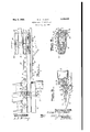
- FIG. 1 is a plan view of the stubbleward end of a harvester cutting mechanism and attached parts illustrating my invention
- Figure 2 is an enlarged section on the line 22 of Figure 1;
- Figure 3 is an enlarged section on the line 3-3 of Figure 1.
- the finger bar 1 is an angle steel bar positioned with its legs 2 and 3 terminating one above the other, the apex 4 placed forwardly' and having its edge ground to a flat vertical surface a to provide a back friction surface for the knife bar.
- Each of the guard fingers 5 have their rear portions 6 extended downwardly, parallel with the leg 3 of the finger bar 1, and between said portion and the leg 3 is interposed a flat steel plate 7, the guard fingers extending forwardly in a plane bisecting the angle of the finger bar.
- a bolt 8 rigidly secures theportion 6 and the plate 7 to the leg 3, and is further utilized to attach, to the inner side of the leg 3, the pan or bottom 9 of the platform conveyor of a harvester.
- the upper end 10 of the steel plate 7, of which there is one to'each guard finger, is bent forwardly to a horizontal position and acts as a friction plate for the cutter bar 11 on which are mounted the knife sections 12, the rear side of the cutter bar 11 abuts against the vertical edge a of the finger bar.
- the guard fingers are provided with the usual type of ledger plates 13 secured on the fingers substantially in a plane bisecting the angle of the finger bar and upon which the cutter moves, the latter being held in place by keeper members 14, of a common type, secured on the leg 2 of the finger bar 1 by bolts 15.
- the finger bar 1 is reinforced by a solid bar 16, triangular in cross section, secured within the finger bar 1 bybolts l7 and rigidly attached to the front frame bar 18 of a harvester by bolts 19.
- the knife head 20 is supported in a member 21 preferably made of pressed steel and having a rear lower portion bent to parallelism with the leg 3 to which it is secured by bolts 22.
- a keeper plate Z has a horizontal portion 23, and a rear portion 24 bent in parallelism with the leg 2 of the bar 1 and held securely in position thereon by bolts 17.
- a channel guide piece 25 is riveted to the forward vertical portion 26 of the member 21.
- the knife bar 11 is securely riveted as shown.
- the pitman c is attached to the knife head 20.
- brackets 29 inverted V-shaped brackets 29, the same bolt 15 that holds the keepers 14 in place being utilized to secure the brackets to the leg 2.
- the usual type of wooden bar 30 forms part of the platform conveyor frame and is scoured to a vertical part 31 of the bracket 29 by bolts 32.
- the conveyor rollers 33 are supported on the bar 30 in a'well known manner.
- What I claim is 1.
- An angle steel finger bar for harvesting machines positioned with its legs angularly disposed to a horizontal plane and having its secured thereon, a raekee member-therear portionof-which'is bent to conform to the inclination of the lower leg of the finger bar,
- a triangular bar located within the ringerbar, .a bolt securing said keeper and triangular bar'to' the upper leg of the finger bar, and a bolt securing the bracket member and triangular bar to the lowerlegofthe finger. bar.
Landscapes
- Life Sciences & Earth Sciences (AREA)
- Environmental Sciences (AREA)
- Harvesting Machines For Root Crops (AREA)
Description
M y 3, 1932- R. c. LIVESAY CUTTER BAR FOR HARVESTERS Filed Aug. 31, 1929 am 8 a 6& a 3 m on 8 mm i k p INYENTDR RBI-DEFT ELLFL'VE SAY TTY- Patented May 3, 1932 nite; s rens etFIcE ROBERT C. LIVESAY, OF MOLINE, ILLINOIS, ASSIGNOR TO DEERE & COMPANY, 01 MOLINE, ILLINOIS, A CORPQBATIGN OF ILLINOIS CUTTER BAR FOR I-IARVESTERS Application filed August 31, 1929. Serial No. 389,704.
My invention relates to harvesting machines, and more particularly to the cutting mechanism, and has for its object to eliminate possible clogging of the parts when in oper- 5, ation in the harvest, and a further objectis to so construct and assemble the mechanism that a greater degree of strength is presented to easily withstand the arduous work to which it may be subjected.
numerals indicate identical parts Figure 1 is a plan view of the stubbleward end of a harvester cutting mechanism and attached parts illustrating my invention;
Figure 2 is an enlarged section on the line 22 of Figure 1; and,
Figure 3 is an enlarged section on the line 3-3 of Figure 1.
The finger bar 1 is an angle steel bar positioned with its legs 2 and 3 terminating one above the other, the apex 4 placed forwardly' and having its edge ground to a flat vertical surface a to provide a back friction surface for the knife bar. Each of the guard fingers 5 have their rear portions 6 extended downwardly, parallel with the leg 3 of the finger bar 1, and between said portion and the leg 3 is interposed a flat steel plate 7, the guard fingers extending forwardly in a plane bisecting the angle of the finger bar. A bolt 8 rigidly secures theportion 6 and the plate 7 to the leg 3, and is further utilized to attach, to the inner side of the leg 3, the pan or bottom 9 of the platform conveyor of a harvester. The upper end 10 of the steel plate 7, of which there is one to'each guard finger, is bent forwardly to a horizontal position and acts as a friction plate for the cutter bar 11 on which are mounted the knife sections 12, the rear side of the cutter bar 11 abuts against the vertical edge a of the finger bar. The guard fingers are provided with the usual type of ledger plates 13 secured on the fingers substantially in a plane bisecting the angle of the finger bar and upon which the cutter moves, the latter being held in place by keeper members 14, of a common type, secured on the leg 2 of the finger bar 1 by bolts 15.
At the knife head end of the mechanism Referring to the drawings in which similar I the finger bar 1 is reinforced by a solid bar 16, triangular in cross section, secured within the finger bar 1 bybolts l7 and rigidly attached to the front frame bar 18 of a harvester by bolts 19. The knife head 20 is supported in a member 21 preferably made of pressed steel and having a rear lower portion bent to parallelism with the leg 3 to which it is secured by bolts 22. A keeper plate Z) has a horizontal portion 23, and a rear portion 24 bent in parallelism with the leg 2 of the bar 1 and held securely in position thereon by bolts 17.
A channel guide piece 25 is riveted to the forward vertical portion 26 of the member 21. To an extension 28 of the part 27, of the knife head 20, the knife bar 11 is securely riveted as shown. The pitman c is attached to the knife head 20.
At intervals'to the inner side of the leg 2 of the bar 1, and shown only in full lines in Figure 3 and in dotted lines in Figure l, are
inverted V-shaped brackets 29, the same bolt 15 that holds the keepers 14 in place being utilized to secure the brackets to the leg 2.
The usual type of wooden bar 30 forms part of the platform conveyor frame and is scoured to a vertical part 31 of the bracket 29 by bolts 32. The conveyor rollers 33 are supported on the bar 30 in a'well known manner.
By utilizing an angle steel bar for a finger bar with its apex positioned forwardly and with both legs angled to the horizontal, I am enabled to secure thereto the various parts of the cutting mechanism in an effective and economical manner, and which, in operation over certain soft and adhesive soil, will escape an'accumulation thereof and avoid an undue wear of the bar and clogging of the fingers and knife.
What I claim is 1. The combination with a harvester frame bar, of an angle steel finger bar mounted on the frame bar and positioned to present one leg extending downwardly and rearwardly and the adjoining leg extending upwardly and rearwardly, guard fingers mounted on and the adjoining leg extending upwardly and rearwardly, guardfingers securedon the downwardly extending leg, and ledger plates secured on the guard fingers in a plane bisecting theangle of the-finger bar.
4, The combination with a harvester frame the frame barand positioned to present a bar, ofan angle steel finger bar mounted on 7 platform conveyor beam secured on said bracket.
8. An angle steel finger bar for harvesting machines positioned with its legs angularly disposed to a horizontal plane and having its secured thereon, a raekee member-therear portionof-which'is bent to conform to the inclination of the lower leg of the finger bar,
"a triangular bar located within the ringerbar, .a bolt securing said keeper and triangular bar'to' the upper leg of the finger bar, and a bolt securing the bracket member and triangular bar to the lowerlegofthe finger. bar.
7 ROBERT C. .LIVESAY.
lower leg-extending downwardly and mean iwardly and an upper leg extending upwardly and rearwardly, a flat vertical surfaceat the outer: angle of the finger bar, guard fingers secured on thelower leg of the finger bar, afriction plateinterposed between the (guard fingerand said lower leg and having its upper portion bent forward horizontally, a. cutter bar op'erativelysu-pported on said .portion and in contact with said flat surface, :and, means to secure'the guard fingers and said "plate; tothe finger bar.
5. The combination with a harvester frame ibar, ofian angle 'steelifinger bar mounted on the-frame bar and: positioned to present" one zie'leg. extending downwardly and :rearwardly landatheladjoining "leg extending upwardly :andfor wardly, guard fingers mounted on the lower leg, a cutter "baroperatively supported'on'theguardfingers, and keeper members 'having their rear portions bent in parallelism with said upwardly extending-leg .andise- -curedthereto;
:16. The combination with a :harvester I :framebar, of an' angle steel finger bar mounted on the'frame bar and positioned tolpresent .a lower leg extending downwardly and rear-- lwardly and an upper leg extending upwardly land rearwa-rdly,:guardfingers 'mounted on the lower leg,l:a :cutter bar supported on the guardv'fingers, abracket positioned on'the .rearf ofrsaid; upper leg," keeper" members having their FIQaT'POIlJlOHS bent in parallelism with said upper leg, and'means'to "secure said bracket and keepers to thefinger bar.
7. The combination with a harvester frame :bar, of an: angle steel finger bar positioned mounted on thei'lowerr leg ofsaid bar, a cutfter barsupported on the guard fingers, an inverted 'V-shaped bracket positioned on the "rear of the upper leg of the finger bar, a bolt securing said bracket to the finger bar, and a
Priority Applications (1)
| Application Number | Priority Date | Filing Date | Title |
|---|---|---|---|
| US389704A US1856488A (en) | 1929-08-31 | 1929-08-31 | Cutter bar for harvesters |
Applications Claiming Priority (1)
| Application Number | Priority Date | Filing Date | Title |
|---|---|---|---|
| US389704A US1856488A (en) | 1929-08-31 | 1929-08-31 | Cutter bar for harvesters |
Publications (1)
| Publication Number | Publication Date |
|---|---|
| US1856488A true US1856488A (en) | 1932-05-03 |
Family
ID=23539369
Family Applications (1)
| Application Number | Title | Priority Date | Filing Date |
|---|---|---|---|
| US389704A Expired - Lifetime US1856488A (en) | 1929-08-31 | 1929-08-31 | Cutter bar for harvesters |
Country Status (1)
| Country | Link |
|---|---|
| US (1) | US1856488A (en) |
Cited By (1)
| Publication number | Priority date | Publication date | Assignee | Title |
|---|---|---|---|---|
| US20060150607A1 (en) * | 2002-10-08 | 2006-07-13 | Gustav Schumacher | Cutter bar |
-
1929
- 1929-08-31 US US389704A patent/US1856488A/en not_active Expired - Lifetime
Cited By (2)
| Publication number | Priority date | Publication date | Assignee | Title |
|---|---|---|---|---|
| US20060150607A1 (en) * | 2002-10-08 | 2006-07-13 | Gustav Schumacher | Cutter bar |
| US7313903B2 (en) * | 2002-10-08 | 2008-01-01 | Gustav Schumacher | Cutter bar |
Similar Documents
| Publication | Publication Date | Title |
|---|---|---|
| US2892298A (en) | Pickup device | |
| US2575120A (en) | Bean harvester catcher attachment | |
| US3566592A (en) | Mower guard | |
| US3812661A (en) | Harvesting machine with crop saving attachment | |
| US1580646A (en) | Guard for grain-binder conveyers | |
| US1856488A (en) | Cutter bar for harvesters | |
| US1917604A (en) | Sickle guard and shield | |
| US2102710A (en) | Harvester | |
| US2298121A (en) | Harvesting machine | |
| US3038289A (en) | Rotary lawn mower guard | |
| US2071844A (en) | Windrow harvester | |
| US2623310A (en) | Wheel track attachment for tractors | |
| US2535960A (en) | Tractor-mounted beet harvester | |
| USRE21604E (en) | Harvester | |
| US3114230A (en) | Double sickle bar mower | |
| US2291182A (en) | Endless chain cutter for mowing and harvesting machines | |
| US1979010A (en) | Cutting apparatus | |
| US2700860A (en) | Mower assembly for tractors | |
| US2565800A (en) | Harvester for ladino clover seed | |
| US1912583A (en) | Cutting means for graders or like implements | |
| US2706374A (en) | Reciprocating cutter assembly | |
| US1520456A (en) | Pick-up attachment for harvesters | |
| US1832936A (en) | Harvester | |
| US2146521A (en) | Harvester | |
| US2503079A (en) | Shield for agricultural implements |