US1856479A - Slip for rotary drilling machines - Google Patents
Slip for rotary drilling machines Download PDFInfo
- Publication number
- US1856479A US1856479A US415248A US41524829A US1856479A US 1856479 A US1856479 A US 1856479A US 415248 A US415248 A US 415248A US 41524829 A US41524829 A US 41524829A US 1856479 A US1856479 A US 1856479A
- Authority
- US
- United States
- Prior art keywords
- slip
- cage
- liner
- slips
- filler
- Prior art date
- Legal status (The legal status is an assumption and is not a legal conclusion. Google has not performed a legal analysis and makes no representation as to the accuracy of the status listed.)
- Expired - Lifetime
Links
- 238000005553 drilling Methods 0.000 title description 4
- 239000000945 filler Substances 0.000 description 15
- 241000239290 Araneae Species 0.000 description 9
- 238000010276 construction Methods 0.000 description 6
- VQKFNUFAXTZWDK-UHFFFAOYSA-N alpha-methylfuran Natural products CC1=CC=CO1 VQKFNUFAXTZWDK-UHFFFAOYSA-N 0.000 description 1
- 239000003129 oil well Substances 0.000 description 1
- 238000005728 strengthening Methods 0.000 description 1
- 230000000153 supplemental effect Effects 0.000 description 1
Images
Classifications
-
- E—FIXED CONSTRUCTIONS
- E21—EARTH OR ROCK DRILLING; MINING
- E21B—EARTH OR ROCK DRILLING; OBTAINING OIL, GAS, WATER, SOLUBLE OR MELTABLE MATERIALS OR A SLURRY OF MINERALS FROM WELLS
- E21B19/00—Handling rods, casings, tubes or the like outside the borehole, e.g. in the derrick; Apparatus for feeding the rods or cables
- E21B19/10—Slips; Spiders ; Catching devices
Definitions
- This invention relates to improvements in slips particularly ydesigned for use 1n rotary drilling machines y,tor suspending drll'lrpipe casing,'tubing and the like.
- the suspended drill pipe or the like may [be ofenormous weight; consequently, the slips aindcooperating parts must be very strong and durable.
- the present invention relates to that type of slips commercially known as separable liner slips, e., slips including a pipe contacting and/or gripping fele'ment that may be renewed or replaced 'when worn. f
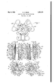
- Fig. ⁇ 1 is a top plan view of a series of a downwardly tapering annular slips embodying my invention, positioned around a section of tubing;
- Fig. 2 a vertical section taken on the line II-II of Fig. l, showing the slips arranged in a bushing or spider;
- Fig. 3 a horizontal section taken on the i line III-III of Fig. 2;
- I For retaining the slip liners 9 in place and for forming a part of the body of the slips, I provide back or filler elements ll, extending vertically between the top and bottom of the cage members and formed with inner walls 11a having vertical recesses 12 therein yfor receiving the backs'of the slip liners 9.
- Said elements 1l are preferably'hollow in construction and have strengthening ribs ⁇ l3 and annular outer walls 14, the lower portions of the walls are tapered downwardly at the same angle of inclination as the walls of the opening 3 in the bushing or spider.
- I provide a plurality of assemblyrrods or pins adapted to pass downwardly of the 'slips Vthrough aligned openings ⁇ 16 and 17 of the cage members 4, and openingslvSand 19 of the fillerr elements 1l.
- the rods .15 are secured' against verti-v :linerslQ by manipulation of the rods or' pins '15.
- spider may be effected by raising thev tubing B, thus moving the liners 9 andthe members 26v'upwardly until the tapers ofsaid members become disengaged from ythe ytapers ofv their respective i'illerV elements 24, therebyT releas-V ing the loutward pressure of the slips upon thel walls of the bushingor spi-der opening 8 to permit withdrawal therefrom.
- body including a .cagev elementari@ Aa filler element, a replaceable liner positioned between! and maintained in position between the cageand the rfiller element, said cage element comprising'anfopen ⁇ frame-like structure having top, bottom and side ortions, anassem- .bly rod @Xtendiiig throng Ythe viiller lment and" engaging the top iid bottom perilous of the cage, and connecting meanson the top portion of the cage to rod d4, nl a sup 'of 'the ehagcterfdesdbed; a body'including a Cage ele'lnentfand a lfiller element, a replaceable liner positionedbetween and maintained in position between the cage and the filler element,sad c.age element comprising an Vopen Yframefliflre structure having tQPJbO-iitom and.
- a slip of the character described a plurality of segmental cage members, each provided With a, mounting for a slip liner, a, slip liner mounted on each cage member for engaging tubing, a, iller element in each cage member for backing the slip liner, and a tapered element (1o-operating with each slip liner whereby the slip releases upon an upward movement of the tubing.
Landscapes
- Engineering & Computer Science (AREA)
- Life Sciences & Earth Sciences (AREA)
- Geology (AREA)
- Mining & Mineral Resources (AREA)
- Mechanical Engineering (AREA)
- Physics & Mathematics (AREA)
- Environmental & Geological Engineering (AREA)
- Fluid Mechanics (AREA)
- General Life Sciences & Earth Sciences (AREA)
- Geochemistry & Mineralogy (AREA)
- Earth Drilling (AREA)
Description
May 3, 1932. E. E. GREVE SLIP FOR ROTARY DRILLING MACHINES Fi;.ed Dec. 19, 1929 Patented May 3, 1932 ,UNITED STATES VPxrsN'r- OFFICE EDGAR E. GREVE, F BELLEVUEZIPENN SYLVAN IA, ASSIGNOR, BY MESNE ASSIGNMENTS,
T0 OIL WELL SUPPLY COMPANY, OF PITTSBURGH, PENNSYLVANIA., A CORPORA- "rroNV orV NEW JERSEY SLIP FOR ROTARY DRILLIN G MACHINES y,Application mea December 19,1929. serial No. 415,248.
. This invention relates to improvements in slips particularly ydesigned for use 1n rotary drilling machines y,tor suspending drll'lrpipe casing,'tubing and the like.
yio
" As isy well known in the art of rotary drill- Vingsl ips of the character to which this .1nvention yrelates are employed in connection witha spider or bushing disposed inthe yrotary tableof the rotary drilling machine, fand in illustrating an lapplication of my 1nvention, I have shown aportion of a bushing 'or'spider 'of a rotary into vwhich the slips are introduced and from which they may be readily removed. Y
The suspended drill pipe or the like may [be ofenormous weight; consequently, the slips aindcooperating parts must be very strong and durable. The present invention relates to that type of slips commercially known as separable liner slips, e., slips including a pipe contacting and/or gripping fele'ment that may be renewed or replaced 'when worn. f
' I vam aware that replaceable liner slips are broadly old. As heretofore constructed, however, such slips have been the cause of considerable, trouble vwhen employed, due to many causes; for example, the manner of ati taching the replaceable liner to the slip body,
the construction of the slip body, the diificulty in applying and removing the. liner from the body, and the troubles encountered due to the slips becoming stuck or wedged in the spider.
Among the objects of the present invention are; to provide a strong and efficient replaceable liner slip of the character specified; to provide a new and improved body construction; to provide ya construction embodying simple means for ydetachably securing the liner elementto the slip; and to. provide a slipconstruction embodying means for aiding in el'ecting a removal ofthe 'slips from the bushing or spider. e u AOther objects and advantages of my inventionwill be hereinafter specifically stated '.or become apparent from the specification taken yin connection with the accompanying 1 drawings, wherein:
Fig.` 1 is a top plan view of a series of a downwardly tapering annular slips embodying my invention, positioned around a section of tubing;
Fig. 2, a vertical section taken on the line II-II of Fig. l, showing the slips arranged in a bushing or spider;
Fig. 3, a horizontal section taken on the i line III-III of Fig. 2;
like structure having a top 5, a bottom 6 and side portions 7, all preferably comprising an integral structure.l The general configuration ofthe cage elements is segmentary,as will be readily understood, to enable the slips to be lassembled around a section of tubing B or the like, as in Fig. l. Vertically eX- tending slip liner-receiving openings 8 are provided at the inner portions of the cage membersfor receiving serrated slip-liners 9, said'liners when positioned on the respective cages extend between the top 5 and the bottom 6 of the cage members. Vertical eX- tending lateral projecting flanges 10 are formed on the liners for seating the same in operative position against the side portions 7 of the cage members.
For retaining the slip liners 9 in place and for forming a part of the body of the slips, I provide back or filler elements ll, extending vertically between the top and bottom of the cage members and formed with inner walls 11a having vertical recesses 12 therein yfor receiving the backs'of the slip liners 9. (See Fig. Said elements 1l are preferably'hollow in construction and have strengthening ribs`l3 and annular outer walls 14, the lower portions of the walls are tapered downwardly at the same angle of inclination as the walls of the opening 3 in the bushing or spider.
Y Y To assemble the slips and secure the parts thereof together, I provide a plurality of assemblyrrods or pins adapted to pass downwardly of the 'slips Vthrough aligned openings` 16 and 17 of the cage members 4, and openingslvSand 19 of the fillerr elements 1l. The rods .15 are secured' against verti-v :linerslQ by manipulation of the rods or' pins '15. Vhen assembled theslipsare positioned in -,or withdrawn from the bushing or spider by means ofthe handles 23. l
" To prevent 'sticking of -thefslip's the bushingor spiderband .to facilitate withi drawalA therefrom, Ii-have, vshown a Vmodied l slip construction in'A Figs. 4 and 5 of the c drawingsl f The v filler,elements 24,' thereof Y are of Y'substantially the same. construction slip liners 9,
- Ymembers. and liners andthe filler elements and configuration asthe liller elements 11, with the addition :of aisubstantially ydeeper vertically` extending; recess 24a, one wall of which is' provided.'l witha .downwardly eX- `tendin'g divided taper 25,5thekangle of pinv clina'tion of said taper being slightly greater Y than the angle of'inclination of the ,taper of slipnreceiving lopening 3 ofthelbUShing or spider.r Slidably mountedon said taper nl provide secondary Vslipmeinbers or supplemental filler members26, these members are of wedge form and the inner faces are straightl tofform -a backing for the renewable It will be noted that'thevertical length of theA slipl members 25v and the liners 9 is slightlyless than thedistance between the top and bottom portions of the cage members 4, to permit a relative motion between said I y Should the slips become vstuck in thespider, alrelease of the slips from the bushing or 1L In a vbodyv including a cage` element anda ller element,y and a replaceable liner positioned between and maintained, in position between they cage and 'the filler element, said'y cage lture Vhaving top, bottom` and sideportions. 2. In a slip'of thev character des eribedl,l a
spider may be effected by raising thev tubing B, thus moving the liners 9 andthe members 26v'upwardly until the tapers ofsaid members become disengaged from ythe ytapers ofv their respective i'illerV elements 24, therebyT releas-V ing the loutward pressure of the slips upon thel walls of the bushingor spi-der opening 8 to permit withdrawal therefrom. V
flm V -f slip of the character described, a
element comprising an open frame-likeistrucisA connected,
body including a cage'element and a ller element, a replaceable liner positioned between and maintained in position between the cageand the filler element, said cage element Coiriprsingan .open frameelikestrugfiire havingtop, bottoin'xand. side portions, Vand an assembly rod extending through the filler element'and engaging the top and bottom portensothe cage.. 1 i n :l 1
`3. In: a .slipioistheeharacter described, 2L
body including a .cagev elementari@ Aa filler element, a replaceable liner positioned between! and maintained in position between the cageand the rfiller element, said cage element comprising'anfopen` frame-like structure having top, bottom and side ortions, anassem- .bly rod @Xtendiiig throng Ythe viiller lment and" engaging the top iid bottom perilous of the cage, and connecting meanson the top portion of the cage to rod d4, nl a sup 'of 'the ehagcterfdesdbed; a body'including a Cage ele'lnentfand a lfiller element, a replaceable liner positionedbetween and maintained in position between the cage and the filler element,sad c.age element comprising an Vopen Yframefliflre structure having tQPJbO-iitom and. Sid@ Aliloito'n, an assembly rod extending through fthe filler element and engaging 1the .topfalfldrbbttom kpor-r tOIiS Of the Cage," C0,111recitingv means Oii'the" top portioll'f the cage t0 Whifih'the assembly rod is connected, and al handle pivqtally'rsle- 4 cured to said connecting` means,
VV5. vIn a SlipV 0f the Character, described, .a
@lenient @replaceable .linerifereiigiagirig trib- `ing positioned between and maintained' in position between ,thecage and filler elements, and cooperating taper vmeans between YVthe liner and filler element for -releasiiiglthe Slip vupon an upward' moveiieritolf the tubingE 6- fIri a Slipv A0f' the .Character described; a body including e Cage @lemritaild a ii'llereepiment, a replaceable linerV for-engagingtubing positioned between and '1 naintairiedv in t' PS-tori between the Cage and filler elements, and cooperating y taper Ineans- Vbetween the liner and filler element for releasing the slip 1112011 an upward Ymorerient of; the tubing,y Said taper means. including a' wedging element.l ,i
7. ln a slip o-f the character described, a
plurality .ofsegmental cage members, each .provided with al mounting for a slip liner, a
slip liner mounted on each Vcage member, and
-a filler element in Veach cage member -forbacling the slip liner. p 'f l ,n Y y Y.
`8.k In a slip of the character. described, a
plurality V0i segmental Cage members, each provided with 2i mountirigior 2. Slip. liner, a'slip liner mounted@ each .Cage member, a
Viller element in each cage member, and-means for releasably Securing @gil iller; element in g.;
position in its respective cage member for backing the slip liner. v
9. In a slip of the character described, a plurality of segmental cage members, each provided With a, mounting for a slip liner, a, slip liner mounted on each cage member for engaging tubing, a, iller element in each cage member for backing the slip liner, and a tapered element (1o-operating with each slip liner whereby the slip releases upon an upward movement of the tubing.
In testimony whereof I affix my signature.
- EDGAR E. GREVE.
Priority Applications (1)
| Application Number | Priority Date | Filing Date | Title |
|---|---|---|---|
| US415248A US1856479A (en) | 1929-12-19 | 1929-12-19 | Slip for rotary drilling machines |
Applications Claiming Priority (1)
| Application Number | Priority Date | Filing Date | Title |
|---|---|---|---|
| US415248A US1856479A (en) | 1929-12-19 | 1929-12-19 | Slip for rotary drilling machines |
Publications (1)
| Publication Number | Publication Date |
|---|---|
| US1856479A true US1856479A (en) | 1932-05-03 |
Family
ID=23644931
Family Applications (1)
| Application Number | Title | Priority Date | Filing Date |
|---|---|---|---|
| US415248A Expired - Lifetime US1856479A (en) | 1929-12-19 | 1929-12-19 | Slip for rotary drilling machines |
Country Status (1)
| Country | Link |
|---|---|
| US (1) | US1856479A (en) |
-
1929
- 1929-12-19 US US415248A patent/US1856479A/en not_active Expired - Lifetime
Similar Documents
| Publication | Publication Date | Title |
|---|---|---|
| US1545039A (en) | Well-casing straightening tool | |
| US2298507A (en) | Elevator | |
| US1856479A (en) | Slip for rotary drilling machines | |
| NO853288L (en) | Fluid / fluid separator. | |
| US2047112A (en) | Earth boring drill | |
| US1758108A (en) | Slip construction | |
| US2141880A (en) | Auger shaft | |
| US1111535A (en) | Hydraulic rotary drilling-machine. | |
| US1347771A (en) | wright | |
| US970880A (en) | Well-boring machine. | |
| US1729940A (en) | Combination casing ring and elevator | |
| US1184037A (en) | Detachable drill-bit. | |
| US825412A (en) | Centrifugal liquid-separator. | |
| US1929813A (en) | Pump | |
| US2144944A (en) | Well swab | |
| US1649208A (en) | Swivel attachment | |
| US1262241A (en) | Well-cleaning device. | |
| US1693502A (en) | Apparatus for gripping pipes, rods, or the like | |
| US736219A (en) | Means for clearing well-strainers. | |
| US1740849A (en) | Packing sleeve for overshots | |
| US1921547A (en) | Tubing catcher | |
| US1565430A (en) | Drill | |
| US1767024A (en) | Centrifugal pipe-mold structure | |
| US1164435A (en) | Pile-core. | |
| US1375964A (en) | Locked-carriage pipe-spider |