US1856472A - Meat rack for refrigerator cars - Google Patents
Meat rack for refrigerator cars Download PDFInfo
- Publication number
- US1856472A US1856472A US541398A US54139831A US1856472A US 1856472 A US1856472 A US 1856472A US 541398 A US541398 A US 541398A US 54139831 A US54139831 A US 54139831A US 1856472 A US1856472 A US 1856472A
- Authority
- US
- United States
- Prior art keywords
- meat
- casing
- car
- supporting
- shock absorbing
- Prior art date
- Legal status (The legal status is an assumption and is not a legal conclusion. Google has not performed a legal analysis and makes no representation as to the accuracy of the status listed.)
- Expired - Lifetime
Links
- 235000013372 meat Nutrition 0.000 title description 32
- 230000035939 shock Effects 0.000 description 43
- 230000008093 supporting effect Effects 0.000 description 32
- 239000006096 absorbing agent Substances 0.000 description 8
- 238000005266 casting Methods 0.000 description 2
- 230000006835 compression Effects 0.000 description 2
- 238000007906 compression Methods 0.000 description 2
- 238000009413 insulation Methods 0.000 description 1
- 239000012774 insulation material Substances 0.000 description 1
- 230000004048 modification Effects 0.000 description 1
- 238000012986 modification Methods 0.000 description 1
Images
Classifications
-
- B—PERFORMING OPERATIONS; TRANSPORTING
- B61—RAILWAYS
- B61D—BODY DETAILS OR KINDS OF RAILWAY VEHICLES
- B61D45/00—Means or devices for securing or supporting the cargo, including protection against shocks
- B61D45/008—Shock absorbing devices
Definitions
- his invention relates to improvements in meat racks for refrigerator cars.
- the main object of my invention is to over- 16 come this difficulty by providing resilient sup porting means in connection with the meat racks of refrigerator cars to cushion and absorb the damaging shocks, thereby protecting I the load suspended from the racks from damage.
- a more specific object of the invention is to provide a shock absorbing supporting means for suspending the meat racks within the car.
- Another object of theinvention is to pro- 29 vide yielding shock absorbing means for suspending the meat racks of refrigerator cars wherein the yielding action of the suspending means is dampened by friction mechanism.
- Figure 1 is a transverse, vertical sectional view through the upper portion of a refrigerator car, illustrating my improvements in connection therewith.
- Figure 2 is a horizontal sectional View, partly broken away, corresponding substantially to the line 22 of Figure 1'.
- Figure 3 is a vertical sectional View of one of a plurality of shock absorbing supports for suspending the meat rack.
- Figure 1 is a horizontal sectional view on the line 4-t of Figure 3.
- Figure 5 is a verticalsectional view of the upper portion of one of a plurality of shock absorbing supports employed to suspend the ends of the meat rack.
- Figure 6 is a view similar to Figure 8, but illustrates a different embodiment of the supporting device.
- Figure 7 is a vertical sectional view through one of a plurality of shock absorbers for supporting the ends of the rack from the car wall, involving substantiallythe same shock absorbing means as illustrated in Figure 6.
- 10 indicates the side wall of a refrigerator car, said wall comprising'an inner sheathing 11, an outer sheathing 12, and interposed insulation material 13.
- the car roof is indicated by 14- and is supported by the usual longitudinally extending beams 15.
- Insulation 16 is provided on the inner side of the roof and covered and protected by the inner sheathing 1?.
- Transverse beams 18 extend from side to side of the car beneath the roof and are spaced therefrom, as shown in Figure 1. The opposite ends of these beams are fixed in the side walls of the car.
- the beams 18 form supporting means from which the meat rack is suspended.
- the usual carlines 118 are provided for supporting the roof,
- the ceiling 19 is secured to the bottom of the carlines 118 and beams 18, as shown in Figure 1.
- a meat rack composed of a plurality of longitudinally extending bars 2020 and transverse connecting rods 2121.
- the bars 2020 are arranged in spaced pairs and are of greater thickness in height than the rods 2121.
- the rods 2121 extend transversely through the bars 20-20, the latter being provided with suitable openings to accommodate the rods.
- the rods 20 are hollow, as shown in Figure 5, that is, they are preferably tubular members.
- the connected rods and bars form a grid structure which serves to suspend the usual hooks on which the meat is hung, one of these hooks being shown in Figure 1 and indicated by 22.
- each rod 21 is further suspended by hooklike members 2323 which are supported by shock absorbers BB mounted on top of the beams 18.
- shock absorbers BB mounted on top of the beams 18.
- three such shock absorbing supporting members B are provic ed for each rod 21 l etween the ends there- A of, the same being spaced apart as shown and having the hook members 23 thereof respectively disposed between adjacent pairs of the longitudinal bars 2020.
- Each shock absorbing supporting member B comprises a base casting 24 which has spaced bottom flanges 25-25 embracing the corresponding beam 18.
- a casing 26 is mounted on top of the base member 24 and has the lower portion'thereof enlarged as indicated at 27 thereby providing an annular limiting shoulder 28.
- the bottom end of the casing 26 is provided with flanges 2929 at opposite sides thereof by which the same is secured to the base member 24, rivets being employed for this purpose, which extend v movement of the friction shell.
- a friction shell 30 is telescoped within the casing 26, the shellbeing open at opposite ends and havlng-inter or friction surfaces 31'31 at theopen upper end.
- Each supporting hook member 23 has an elongated rodlike shank portion which extends through openings provided in the ceiling 19 of the car, the corresponding beam 18, the base member 24, the follower disc 36, and the wedge block 34.
- the hook member 23 is anchored to the Wedge block by means of a securing nut 37 threaded on the upper end of the shank of the hook.
- each shock absorbing means B yieldingly opposes downward movement of the corresponding supporting hook 23 by means of the combined spring and frictional action of said device. In absorbing a shock due to downward pullon the hook 23, the
- the friction means provides a dampening action during this part of the operation of the shock absorber and in addition opposes greater resistance to downward movement of the 'member 23.
- the spring 35 acts to return all the parts to the normal position, upward movement of the shell 30 being limited by the shouldered engagement thereof with the casing 26.
- Each shock absorbing supporting member A com'prisesa base member 39 having an upstanding securing-flange 40 which is fixed to the side wall of the car by means of bolts extending therethrough.
- the base casting has a casing 41 mounted thereon in all respect similar to the casing 26 hereinbefore described in connection with Figure 3.
- a friction shell 42 similar to the shell 30, is telescoped within-the casing and contains friction shoes 4343, a spring resistance 44, and a wedge member 45, similar to the corresponding parts of Figure 3.
- the wedge member is provided with a pocket 46 at the top thereof in which the outer end of the corresponding rod 21 is seated.
- a retanier bolt 147 is employed, which is anchoredto the wedge block and the supporting bracket 39.
- this shock absorbing device is in all respectssimilarto the device shown in Figure 3, downward movement of the rack forcing the wedge inwardly, first compressing the spring only and then, after movement of the friction shell has been arrested, forcing the friction shoes to slide inwardly of the shell.
- supporting shock absorbing devices AA are provided at opposite ends of each rod 21, the same being fixed to the side walls of the car.
- the entire rack is thus supported at opposite ends by a plurality of shock absorbing devices A, and is .further suspended from the beams 18 by a plurality of shock absorbing devices B-B, three such devices being employed in connection witheach rod 21.
- each shock ab.- sorbing device .0 comprises a casing 47 which is closed at the bottom end and is supported on'the corresponding beam 18.
- the casing 47 is provided with spaced depending flanges 4848 at the bottom end thereof which. embrace opposite sides of the beam 18, securing means being employed extending through these flanges and into the beam.
- a spring 419 is dis posed within the casing and is supported on the bottom wall of the same.
- a spring follower 50 cooperates with the upper end of the spring, and the shank of the hook 28 extends therethrough.
- the hook member 23 is anchored to the follower50 by means of a nut 51 at the upper end ofthe shank thereof.
- Both the spring follower member 50 and the bottom wall of the casing e7 are provided with inwardly extending bosses which engage within the spring L9 to center the same, and restrict downward movement of the follower'50 by engagement with each other, thereby limiting'compression of the spring.
- the shock absorbing device D comprises a casing having a fiat rear wall 52 which has projecting flanges at opposite sides for fixing the same to the wall 11 of the car. Any well-known securing means may be employed for mounting the casing on the wall 11, bolts being herein shown which extend through the flanges of the rear wall.
- the casing contains a spring 53 which is supported on the bottom wall thereof.
- a spring follower 54 is telescoped within'the upper end of the ea ing and bears on the spring
- the spring follower has a depending guide rod 55 formed integral therewith, the rod extending through thebottom wall of the casing and having a nut 56 secured to the lower end thereof for limiting upward movement of the follower 54.
- the follower is provided with an opening 57 which receives the corresponding end of the cooperating rod 21 of the rack.
- front and rear walls of the casing 52 are vertically slotted, as indicated at 58 to permit the necessary reciprocating movement of the rod 21.
- a meat rack for refrigerator cars the combination with connected bars forming a grid structure adapted to receive meat supporting hooks; of shock absorbing means fixed to the walls of the car supporting opposite sides of the grid structure; and additional shock absorbing means anchored to the grid structure inwardly of the sides thereof for suspending said gridrstructure from the top of the car.
- a meat rack for refrigerator cars the combination with longitudinally extending bars and transverse connecting rods forming a grid structure adapted to suspend meat hooks; of bracket means fixed to the walls of the car; means on which the opposite sides of said grid structure is supported; and shock absorbing means interposed between said brackets and the corresponding supporting means.
- bracketv means fixed to the walls of the car; means on which the opposite sides of said grid structure is supported; shock absorbing means interposed between said brackets and the corresponding supporting means; members suspending the grid structure inwardly of the ends thereof, said members having shank portions; fixed follower means at the upper end of each shank portion; fixed supporting means on the car; and shock absorbing means interposed between said fixed supporting meansand each follower.
- a refrigerator car structure the combination with aplurality of fixed :beams at the top of the car extending transversely thereof and spaced lengthwise; of a grid member com-posed of' a plurality of spaced, longitudinally extending bars and transverse rods extending through' the bars and supporting the latter; a plurality of casings supported on said beams; a friction cylinder telescopically slidable within each casing; friction 'means'lnoluding' a wedge member cooperating with each cylinder; spring means opposing relative movement of each casing and cylinder and also opposing relative'movement of the friction means and corresponding cylinder; and means anchored at opposite ends to each wedge member and rod respectively for suspendmg said grid structure.
- a shock absorbing supporting means for meat racks of refrigerator cars the combination with a casing fixedto the car; of a friction shell telescopically slidable within the casing; frictionshoes slidable within the shell; spring resistance means opposing relative movement of :the shell and casing and also opposing relative movement of the shoes and shell; wedge means cooperating with the shoes; and means for suspending the meat rack by said wedgemeans.
Landscapes
- Engineering & Computer Science (AREA)
- Transportation (AREA)
- Mechanical Engineering (AREA)
- Refrigerator Housings (AREA)
Description
May 3, 1932.
A. E. DENTLER 1,856,472
MEAT RACK FOR REFRIGERATOR CARS Filed June 1, 1931 Patented May 3, 1932 QNHED FTATES ARNOLD E. DENTLER, OF CHICAGO, ILLINOIS, ASSIGNOR T W. H. MINER, INQ, OF CHICAGO, ILLINOIS, A CORPORATION OF DELA'WABE MEAT RACK FOE REFBIGERATOR CARS Application filed June 1,
his invention relates to improvements in meat racks for refrigerator cars.
In the transportation of meat by refrigerator cars, damage is frequently caused in transit by the same being shaken and torn from the supporting hooks of the racks through excessive violent vibrations imparted to the car body by the action of the truck springs.
The main object of my invention is to over- 16 come this difficulty by providing resilient sup porting means in connection with the meat racks of refrigerator cars to cushion and absorb the damaging shocks, thereby protecting I the load suspended from the racks from damage.
A more specific object of the invention is to providea shock absorbing supporting means for suspending the meat racks within the car.
Another object of theinvention is to pro- 29 vide yielding shock absorbing means for suspending the meat racks of refrigerator cars wherein the yielding action of the suspending means is dampened by friction mechanism.
Other objects of the invention will more clearly appear from the description and claims hereinafter following.
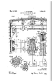
In the drawings, forming a part of this specification, Figure 1 is a transverse, vertical sectional view through the upper portion of a refrigerator car, illustrating my improvements in connection therewith. Figure 2 is a horizontal sectional View, partly broken away, corresponding substantially to the line 22 of Figure 1'. Figure 3 is a vertical sectional View of one of a plurality of shock absorbing supports for suspending the meat rack. Figure 1 is a horizontal sectional view on the line 4-t of Figure 3. Figure 5 is a verticalsectional view of the upper portion of one of a plurality of shock absorbing supports employed to suspend the ends of the meat rack. Figure 6 is a view similar to Figure 8, but illustrates a different embodiment of the supporting device. And Figure 7 is a vertical sectional view through one of a plurality of shock absorbers for supporting the ends of the rack from the car wall, involving substantiallythe same shock absorbing means as illustrated in Figure 6.
1931. Serial No. 541,398.
In said drawings, referring first to the invention illustrated in Figures 1 to 5 inclusive, 10 indicates the side wall of a refrigerator car, said wall comprising'an inner sheathing 11, an outer sheathing 12, and interposed insulation material 13. The car roof is indicated by 14- and is supported by the usual longitudinally extending beams 15. Insulation 16 is provided on the inner side of the roof and covered and protected by the inner sheathing 1?. Transverse beams 18 extend from side to side of the car beneath the roof and are spaced therefrom, as shown in Figure 1. The opposite ends of these beams are fixed in the side walls of the car. The beams 18 form supporting means from which the meat rack is suspended. The usual carlines 118 are provided for supporting the roof,
and the beams 18 are preferably disposed at opposite sides of the same. The ceiling 19 is secured to the bottom of the carlines 118 and beams 18, as shown in Figure 1.
in carrying out my invention as disclosed in Figures 1 to 5 inclusive, I employ a meat rack composed of a plurality of longitudinally extending bars 2020 and transverse connecting rods 2121. As most clearly shown in Figure 1, the bars 2020 are arranged in spaced pairs and are of greater thickness in height than the rods 2121. As shown, the rods 2121 extend transversely through the bars 20-20, the latter being provided with suitable openings to accommodate the rods. In the present instance, the rods 20 are hollow, as shown in Figure 5, that is, they are preferably tubular members. The connected rods and bars form a grid structure which serves to suspend the usual hooks on which the meat is hung, one of these hooks being shown in Figure 1 and indicated by 22. The transverse bars 2121 of the meat rackare supported at opposite ends on shock absorbers A A which are fixed to the side walls of. the car. Between the ends, each rod 21 is further suspended by hooklike members 2323 which are supported by shock absorbers BB mounted on top of the beams 18. As shown in Figure 1, three such shock absorbing supporting members B are provic ed for each rod 21 l etween the ends there- A of, the same being spaced apart as shown and having the hook members 23 thereof respectively disposed between adjacent pairs of the longitudinal bars 2020.
Each shock absorbing supporting member B comprises a base casting 24 which has spaced bottom flanges 25-25 embracing the corresponding beam 18. A casing 26 is mounted on top of the base member 24 and has the lower portion'thereof enlarged as indicated at 27 thereby providing an annular limiting shoulder 28. The bottom end of the casing 26 is provided with flanges 2929 at opposite sides thereof by which the same is secured to the base member 24, rivets being employed for this purpose, which extend v movement of the friction shell.
through the flanges 29 29 and laterally outstanding sections at opposite sides of the base member. .A friction shell 30 is telescoped within the casing 26, the shellbeing open at opposite ends and havlng-inter or friction surfaces 31'31 at theopen upper end. At
converged inwardly. Apair of friction shoes.3333 cooperate with the friction surfaces of the shell and an outer wedge block 34 has wedging engagement with the shoes. A
spring member 35 is disposed within the friction shell 30 and casing26, having the bottom end bearingon the base member 24 and the upper end engaging a spring follower disc 36 which in turn engages the inner ends of the friction shoes. As will be evident, the spring 35 opposes inward movement of the friction shell with respect to the casing 26 and also opposes movement of the friction shoes 3333 inwardly of the shell 30; Each supporting hook member 23 has an elongated rodlike shank portion which extends through openings provided in the ceiling 19 of the car, the corresponding beam 18, the base member 24, the follower disc 36, and the wedge block 34. The hook member 23 is anchored to the Wedge block by means of a securing nut 37 threaded on the upper end of the shank of the hook. A follower plate 38 is preferably interposed between the outer end of the wedge block 34 and the nut 37. As will be evident, each shock absorbing means B yieldingly opposes downward movement of the corresponding supporting hook 23 by means of the combined spring and frictional action of said device. In absorbing a shock due to downward pullon the hook 23, the
same will initially be resisted by the spring 35 only. After a predetermined compression of the spring 35, the lower end of the friction shell 30 will engage the base member 63 24, thereby arresting downward movement of the shell and compelling the friction shoes to move inwardly on the friction surfaces of the shell. As willbe evident, the friction means provides a dampening action during this part of the operation of the shock absorber and in addition opposes greater resistance to downward movement of the 'member 23. The spring 35 acts to return all the parts to the normal position, upward movement of the shell 30 being limited by the shouldered engagement thereof with the casing 26.
Each shock absorbing supporting member A com'prisesa base member 39 having an upstanding securing-flange 40 which is fixed to the side wall of the car by means of bolts extending therethrough. The base casting has a casing 41 mounted thereon in all respect similar to the casing 26 hereinbefore described in connection with Figure 3. A friction shell 42, similar to the shell 30, is telescoped within-the casing and contains friction shoes 4343, a spring resistance 44, and a wedge member 45, similar to the corresponding parts of Figure 3. The wedge member is provided with a pocket 46 at the top thereof in which the outer end of the corresponding rod 21 is seated. A retanier bolt 147 is employed, which is anchoredto the wedge block and the supporting bracket 39. The operation of this shock absorbing device is in all respectssimilarto the device shown in Figure 3, downward movement of the rack forcing the wedge inwardly, first compressing the spring only and then, after movement of the friction shell has been arrested, forcing the friction shoes to slide inwardly of the shell. As will be understood, supporting shock absorbing devices AA are provided at opposite ends of each rod 21, the same being fixed to the side walls of the car. The entire rack is thus supported at opposite ends by a plurality of shock absorbing devices A, and is .further suspended from the beams 18 by a plurality of shock absorbing devices B-B, three such devices being employed in connection witheach rod 21. V
A As illustrated in Figures 6 and 7, spring shock absorbing devices may be substituted for the friction devices A and B. A plurality of such spring shock absorbers CC, shown indetail in Figure 6, are employed in place of the shock absorbing devices. B 'B, and a plurality of shockabsorbing devices D, as shown in Figure 7, are employed in place of the devices AA. Each shock ab.- sorbing device .0 comprises a casing 47 which is closed at the bottom end and is supported on'the corresponding beam 18. The casing 47 is provided with spaced depending flanges 4848 at the bottom end thereof which. embrace opposite sides of the beam 18, securing means being employed extending through these flanges and into the beam. The shank of a hook member 23, corresponding to the hook member hereinbefore described in connection with Figures 1 to5 inclusive, has the shank thereof extending through openings in the ceiling 19, the beam 18, and the bottom wall of the casing 47. A spring 419 is dis posed within the casing and is supported on the bottom wall of the same. A spring follower 50 cooperates with the upper end of the spring, and the shank of the hook 28 extends therethrough. The hook member 23 is anchored to the follower50 by means of a nut 51 at the upper end ofthe shank thereof. Both the spring follower member 50 and the bottom wall of the casing e7 are provided with inwardly extending bosses which engage within the spring L9 to center the same, and restrict downward movement of the follower'50 by engagement with each other, thereby limiting'compression of the spring.
The shock absorbing device D comprises a casing having a fiat rear wall 52 which has projecting flanges at opposite sides for fixing the same to the wall 11 of the car. Any well-known securing means may be employed for mounting the casing on the wall 11, bolts being herein shown which extend through the flanges of the rear wall. The casing contains a spring 53 which is supported on the bottom wall thereof. A spring follower 54 is telescoped within'the upper end of the ea ing and bears on the spring The spring follower has a depending guide rod 55 formed integral therewith, the rod extending through thebottom wall of the casing and having a nut 56 secured to the lower end thereof for limiting upward movement of the follower 54. The follower is provided with an opening 57 which receives the corresponding end of the cooperating rod 21 of the rack. The
front and rear walls of the casing 52 are vertically slotted, as indicated at 58 to permit the necessary reciprocating movement of the rod 21.
As will be evident, when the rack is subjected to shocks or 'ibrations, the same is yieldingly supported by'the springs of the shock absorbers C and D, the springs of the shock absorbers D yieldingly opposing downward movement of the outer ends of the rods 21 of the rack, and the springs of the shock. absorbers C opposing downward movement of the hooks 23 which suspend the rods 21 between the ends thereof.
From the preceding description taken in connection with the drawings, it will be evident that I have provided a yielding shock absorbing supporting means for the entire meat rack of a refrigerator car, thereby avoiding sudden jars to the rack structure due to vibrations of the truck springs and car body, thus preventing the meat suspended on the hooks of the rack from being torn and shaken down. In addition, by employing the friction shock absorbing devices, excessive jars to the meat rack are effectively absorbed, the yielding resistance of the springs of the shock absorbing devices being dampened by the friction means which also provides greater shock absorbing capacity in case of heavy shocks being encountered.
I have herein shown and described what I now consider the preferred manner of carrying out my invention, but the same is merely illustrative and I contemplate all changes and modifications that come within the scope of the claims appended hereto.
I claim:
1. In a meat rack for refrigerator cars, the combination with connected bars forming a'gridlike rack structure for suspending meat supporting heels; of shock absorbing means for suspending said connected bars.
2. In a meat rack for refrigerator cars, the combination with connected bars forming a gridlike rack structure for suspending meat supporting hooks; of spring shock absorbing means for suspending said connected bars.
3. In a meat rack for refrigerator cars, the combination with connected bars forming gridlike rack structure for suspending meat supporting hooks; of friction shock absorbing means for suspending said connected bars.
4. In a meat rack for refrigerator cars, the combination with connected bars forming a grid structure adapted to receive meat supporting hooks; of shock absorbing means fixed to the walls of the car supporting opposite sides of the grid structure; and additional shock absorbing means anchored to the grid structure inwardly of the sides thereof for suspending said gridrstructure from the top of the car.
5. In a meat rack for refrigerator cars, the combination with longitudinally extending bars and transverse connecting rods forming a grid structure adapted to suspend meat hooks; of bracket means fixed to the walls of the car; means on which the opposite sides of said grid structure is supported; and shock absorbing means interposed between said brackets and the corresponding supporting means.
6. In a meat rack for refrigerator cars, the combination with longitudinally extending bars and transverse connecting rods forming acgrid structure adapted to suspend meat hooks; of bracketv means fixed to the walls of the car; means on which the opposite sides of said grid structure is supported; shock absorbing means interposed between said brackets and the corresponding supporting means; members suspending the grid structure inwardly of the ends thereof, said members having shank portions; fixed follower means at the upper end of each shank portion; fixed supporting means on the car; and shock absorbing means interposed between said fixed supporting meansand each follower.
.7. In a refrigerator car structure, the com- .bination withxa plurality of fixed interior beams at the top of the car extending transthrough the bars andsupporting the latter; a plurality of casings supported on said beams; a plurality of supporting elements fixed to the grid structure for suspendinglthe same; a follower anchored to the upper .end of each supporting element and slidable within one of said casings; and means yieldingly opposing movement of said followers with respect to the corresponding casings.
8. In a refrigerator car structure, the combination with aplurality of fixed :beams at the top of the car extending transversely thereof and spaced lengthwise; of a grid member com-posed of' a plurality of spaced, longitudinally extending bars and transverse rods extending through' the bars and supporting the latter; a plurality of casings supported on said beams; a friction cylinder telescopically slidable within each casing; friction 'means'lnoluding' a wedge member cooperating with each cylinder; spring means opposing relative movement of each casing and cylinder and also opposing relative'movement of the friction means and corresponding cylinder; and means anchored at opposite ends to each wedge member and rod respectively for suspendmg said grid structure.
9. In a refrigerator car structure,-the coming the latter; ,a plurality 10f casings supported von said beams; vajfrictioncylinder telescopically slidable within each casing; :fri'ction means including wedge member 00- operating with each cylinder; spring means opposing-relative movement of each casing and cylinderand also-.opposingrelative movement of .the friction :means :and corresponding cylinder; means anchored at :opposite ends .to each "wedge 'and mod respeci 11. Ina shock absorbing-supporting means for meat racks of refrigerator cars, the combination with a'friction casing fixed to the car structure; of friction shoes :slidable within the casing; spring means resisting inward movement .of theshoes; and .a wedge block cooperating with the shoes, said wedge block having means thereon for supporting the rack structure.
12. Ina shock absorbing supporting means for meat racks of refrigerator cars, the combination with a casing fixedto the car; of a friction shell telescopically slidable within the casing; frictionshoes slidable within the shell; spring resistance means opposing relative movement of :the shell and casing and also opposing relative movement of the shoes and shell; wedge means cooperating with the shoes; and means for suspending the meat rack by said wedgemeans.
In witness that I claim the foregoing I have hereunto subscribed my name this 29th day of May, 1931. V
ARNOLD E. DEN TLEZR.
spect to the corresponding-casing; a plural-' ity of casings fixed to the side walls of the car; a supporting member sliclable in each casing, said supporting member having a socket at the top thereof in which the outer end of one of said rods is seated; and spring means opposing movement of said supporting member inwardly of the casing.
10. In a refrigerator car structure, the combination with a plurality of fixedbeams at the' top of the car extending transversely thereof andspaced lengthwise; of a grid member composed of a plurality of spaced, longitudinally extending bars and transverse rods extending through the bars and supportinc
Priority Applications (1)
| Application Number | Priority Date | Filing Date | Title |
|---|---|---|---|
| US541398A US1856472A (en) | 1931-06-01 | 1931-06-01 | Meat rack for refrigerator cars |
Applications Claiming Priority (1)
| Application Number | Priority Date | Filing Date | Title |
|---|---|---|---|
| US541398A US1856472A (en) | 1931-06-01 | 1931-06-01 | Meat rack for refrigerator cars |
Publications (1)
| Publication Number | Publication Date |
|---|---|
| US1856472A true US1856472A (en) | 1932-05-03 |
Family
ID=24159426
Family Applications (1)
| Application Number | Title | Priority Date | Filing Date |
|---|---|---|---|
| US541398A Expired - Lifetime US1856472A (en) | 1931-06-01 | 1931-06-01 | Meat rack for refrigerator cars |
Country Status (1)
| Country | Link |
|---|---|
| US (1) | US1856472A (en) |
Cited By (1)
| Publication number | Priority date | Publication date | Assignee | Title |
|---|---|---|---|---|
| US4038929A (en) * | 1975-09-22 | 1977-08-02 | Sea-Land Service, Inc. | Portable meat railer shipping assembly |
-
1931
- 1931-06-01 US US541398A patent/US1856472A/en not_active Expired - Lifetime
Cited By (1)
| Publication number | Priority date | Publication date | Assignee | Title |
|---|---|---|---|---|
| US4038929A (en) * | 1975-09-22 | 1977-08-02 | Sea-Land Service, Inc. | Portable meat railer shipping assembly |
Similar Documents
| Publication | Publication Date | Title |
|---|---|---|
| US2259049A (en) | Side bearing | |
| US2754768A (en) | Suspension unit for railway vehicles | |
| US1856472A (en) | Meat rack for refrigerator cars | |
| US2367510A (en) | Car truck | |
| US2211462A (en) | Car truck | |
| US2265392A (en) | Shock absorber | |
| US2873693A (en) | Resiliently mounted tie-down support rails | |
| US2552668A (en) | Friction shock absorber for railway car trucks | |
| US2642008A (en) | Railway truck shock absorber mounting | |
| US2687100A (en) | Stabilizer for railway car trucks | |
| US1863714A (en) | Meat rack | |
| EP3691952B1 (en) | Railway truck with elastomeric suspension | |
| US2278012A (en) | Car truck | |
| US2587315A (en) | Railroad car truck | |
| US1883306A (en) | Car construction | |
| US2710582A (en) | Railway truck structure | |
| US2049709A (en) | Shock absorber | |
| US1813706A (en) | Resilient unit for car trucks | |
| US2143154A (en) | Combined spring and friction shock absorber | |
| US2073075A (en) | Car truck | |
| US2206487A (en) | Railway car truck | |
| US2565672A (en) | Shock absorber for railway car trucks | |
| US2427415A (en) | Friction shock absorber | |
| US2663535A (en) | Hydraulic spring hanger | |
| US2747861A (en) | Spring group |