US1856468A - Draft connection - Google Patents
Draft connection Download PDFInfo
- Publication number
- US1856468A US1856468A US376561A US37656129A US1856468A US 1856468 A US1856468 A US 1856468A US 376561 A US376561 A US 376561A US 37656129 A US37656129 A US 37656129A US 1856468 A US1856468 A US 1856468A
- Authority
- US
- United States
- Prior art keywords
- draft
- tractor
- wagon
- implement
- disposed
- Prior art date
- Legal status (The legal status is an assumption and is not a legal conclusion. Google has not performed a legal analysis and makes no representation as to the accuracy of the status listed.)
- Expired - Lifetime
Links
- 241001465754 Metazoa Species 0.000 description 5
- 240000008042 Zea mays Species 0.000 description 5
- 235000005824 Zea mays ssp. parviglumis Nutrition 0.000 description 5
- 235000002017 Zea mays subsp mays Nutrition 0.000 description 5
- 235000005822 corn Nutrition 0.000 description 5
- 210000005069 ears Anatomy 0.000 description 4
- 101100001674 Emericella variicolor andI gene Proteins 0.000 description 2
- 101000952234 Homo sapiens Sphingolipid delta(4)-desaturase DES1 Proteins 0.000 description 1
- XEEYBQQBJWHFJM-UHFFFAOYSA-N Iron Chemical compound [Fe] XEEYBQQBJWHFJM-UHFFFAOYSA-N 0.000 description 1
- HOKDBMAJZXIPGC-UHFFFAOYSA-N Mequitazine Chemical compound C12=CC=CC=C2SC2=CC=CC=C2N1CC1C(CC2)CCN2C1 HOKDBMAJZXIPGC-UHFFFAOYSA-N 0.000 description 1
- 240000000037 Prosopis spicigera Species 0.000 description 1
- 235000006629 Prosopis spicigera Nutrition 0.000 description 1
- 102100037416 Sphingolipid delta(4)-desaturase DES1 Human genes 0.000 description 1
- 230000000694 effects Effects 0.000 description 1
- 206010015037 epilepsy Diseases 0.000 description 1
- 230000037431 insertion Effects 0.000 description 1
- 238000003780 insertion Methods 0.000 description 1
- 239000002184 metal Substances 0.000 description 1
- GWUSZQUVEVMBPI-UHFFFAOYSA-N nimetazepam Chemical compound N=1CC(=O)N(C)C2=CC=C([N+]([O-])=O)C=C2C=1C1=CC=CC=C1 GWUSZQUVEVMBPI-UHFFFAOYSA-N 0.000 description 1
- 229920000136 polysorbate Polymers 0.000 description 1
- 239000002689 soil Substances 0.000 description 1
- 125000006850 spacer group Chemical group 0.000 description 1
Images
Classifications
-
- A—HUMAN NECESSITIES
- A01—AGRICULTURE; FORESTRY; ANIMAL HUSBANDRY; HUNTING; TRAPPING; FISHING
- A01D—HARVESTING; MOWING
- A01D67/00—Undercarriages or frames specially adapted for harvesters or mowers; Mechanisms for adjusting the frame; Platforms
- A01D67/005—Arrangements of coupling devices
Definitions
- This invention relates to draft connections, i and more particularly to connections for hitchiiig an agricultural yimplement and a .wagon to a tractor.
- V v ⁇ Figure 2 is a section on an enlarged scale when the diagonal to permit stant invention is in the nature of an improvement over the draft connections disona-l beam is connected to the tongue of the to disconnect this beam and ⁇ move the same Y.
- vto' one "side a considerable distance in' order of a draft'ani'malbeing hitched to f the wagon, at the'bea-m side of the tongue,A whenthe wa existing dra 'familiar itis necessary, 'desiredl fore and aft adjustment of the wagon, the connections of several parts,
- One of the main objects-of our invention is to provide simple and eiiieientdraft con-"f structure illustrating the position of the parts nections of the characterstated inA which the means4 whereby, .whenthe wagon-is loaded, a'dra-ft' animal can be hitched thereto at the beam side of the tongue without necessity of v when to be attached to the tractor for propellingv moving the beam out ofits normal diagonal lt isition.
- a :further object is to provide a am sorela'ted to the draft member of the implement as to be movable into position, disconnected from vthe .wagon tongue,
- the implement, the beam at this time being so disposed that the implement trails behind the tractor in substantial alignment therewith.
- y ' Figure 1 is a plan view this general ghar iltion inaccordance with our invention as apfamiliar, the diag- ⁇ It is also an objectv of our. invention to mount the beam in lsuch manner that, when it is disposed for attachment tothe tractor, it is also'disposed beneath the draft member ofthe implement for supporting the same,
- a further'object of our invention is to ⁇ rovide means whereby the effective side d ra of the wagon for counter-acting the side draft ofthe iinplement can be variedv to suit conditions.
- Figure 5 is a section taken substantially on line---5 of Figure 4.
- v Figure 6 is a section taken substantially on line 6-6 of Figure 4;
- Figure 7 is a section taken substantially on line 7--7 of Figure 1.
- draft connection is particularly adapted l ourinvention as usedA it is to be understood that it is also adapted connection
- the draft member'2 is of ⁇ and, comprises angle side rails'll and 12 con- A 1 nected adjacent thier forward ends by aplatej 1 3. vThese-rails are connected byv trusses andl usset pla-tes,L certainv of" these trusses, des- 1. l
- ward arm 'of clev1s33',-wh1ch 1s extended for for-use in connecting two vehicles or implements to a tractor in rear of and at opposite sides thereof, and is vnot restricted to use with a corn harvester and a wagon, which are illustrated by way of example.
- the corn harvesterv isl illustrated semi-diagrammatically and comprises a laterally extending elevator 1, whichservesto discharge the ears of corn, ⁇
- a draft member 2 ⁇ extends forward'- ly fromfthe harvester andI is .secured thereto, at 3 fand 4,- in a suitable manner. Atfits forward end,the member 2 is pivoted to drawbar '5 of the tractor on a'horizontal axis, in a it suitablejnanner as by meansof a pin 6 passinglthrou'ghthe forwa rd end of member 2 and throughaloop7 at the rearward'end of the draw bar,.thisloop being normally vclosed by aboltS..
- Beam 20 is thus mounted, at its rearward end, in such manner as to be capable of be ⁇ tongue 19 ing swung about the pivot bolt 21 into the the forward end thereof, by a pivot bolt 24.
- this member comprises upper and ⁇ lower arms 25 and 26, respectively, which may kconveniently be formed. of suitable lengths of strap metal, each of these arms being 'provided with an angularly disposed andy rearwardlyextending element 27.
- theelement 27 extends lengthwise of beam 20 at the upper and lower faces thereof.
- Thesefelements are connected at theirrear-t ward end, byv 'a' stirrup 28 which lits about the rearward portion of beam 20 and serves lto prevent rearward turning movement of :fthe extensionmember about bolt 24 beyond operative' positon.”
- 'l ⁇ he ⁇ outer end portion 'of arms 25fand 26 are slightly offset to extend above and beneath the tongue 19 in con- ⁇ tact'therewithfas in Figure-1.
- a bolt 29 Yextendsthrough the arm and a sleeve spacer ⁇ f30 ,is disposed vabout this bolt' and serves to properly space the outer ends of the arm for ,reception therebetweenof the tongue.
- T e arms are provided, at their outer ends, with'a series'of alignedopening's 31 for reception of a pinj32. provided at its upper endg, with an angularly ydisposed st-opnger.
- This f.; f provides means for :adjusting the pln to corv respond tothe width of the portion of the 'which the member 23 isfat-f tached..
- brace rod'34 issuitably secured to the forrearward end'of beam 20'and is suitably secured thereto asY by means of a bolt 36.
- ⁇ turnbuckle 37 is provided in the rod 34 for tensioning. the same.
- rod 34.- passes 'A strap .40' extends 'forwardly frorii i 20 and-fis secured, at' its forward end, toa
- this link is also proi'ided, at its rearward end I portion, with a longitudinally extending series of y'openings 44 for reception of vzo - hook is adapted for reception of a ring 49 a bolt 45 passing through strap 40,the tongue and link 41.
- this bolt as also passing through the two plates 38 for securing them to the beam.
- the beam- is provided with a series of openings 46spaced apart lengthwise thereof.
- the provision of the v opening in link 41 provides simple ⁇ and eilicient means for adjustin the effective length of this link to suit conditions.
- the openings 46 in the beam 2O are of value as providing l means for adjusting the point of connection wagon acts on the harvester.
- the eye 51 is of proper interiordiameter to permit free sliding f v l 'and aft positions so With'the strap 40 and link 41 attached to' beam 20 at the. point illustrated, the bolt 451 securing the plates ,3S the strap and the link'4 are attached to the beam at some other point,
- the chain 50 provides l a draft connection betweenthe wagon and ⁇ tl'ie'extension member, in that the eye provides an abutment' or bearing for the chain, as well as between the wagon and the link 41,
- the point of connection be- ⁇ ture can readily be adjusted in accordance with variation in the fore and aft positioiisnfi thewagon.
- This is advanta ing it possible to quickly an plurality levelin eous as rendereasily position the wagon in any one of a plurality of fore y that the ears may be dis- -charged from elevator 1 into 4the -wagon at a' aev 'tween the draft chain and the diagonal struc- ⁇ ilus of points lengthwise thereof, suc' ⁇ f cessively, thus avoiding anyV necessityjforr the load b hand which is necessary when t e ears are isclia'rged into the wagon 'at a single point only, or even at the front and rear thereof only.
- the pin 54 is also available 'for insertion through an opening 55 in arm 25 of extension member 23, and through openings extendin the lower arm 26 an ali the extension member 23 against forward 'nt' gned with opening'55.
- the pin 54 serves to holdmovement about its pivot. This is not necessary when operating on level ground or when .traveling up hill, but it is necessary when izo' .
- a U-shapedy bracket 57 is secured a bolt x58 about rail 12 of ⁇ draft member 2.
- the upf per-.arm yof'this bracket carries a projection'- 59 to ywhich a hook 60 is pivoted at 61 on a l nf/When ⁇ etranslliiuiting'I.the harvester fro'mbne scene of operations to another, it fis de-y sirable .that the' harvester trail behind the' 'its ends'secured tof-this extension members ⁇ 1 Beam 20is then attached, by means of clevis,
- a resilient supporting shoe 64 isv providedI 'adjacent the forward end of beam 20- ⁇ r for supporting the' same.- This shoe may con.
- a draft member connecting the implement and the tractor, a diagonal structure comprising a beam connected at its rearward end to the implement and an extension member at the forward end of the beam and detachably connected to the tongue, said extension member being mounted on the beam for relative movement away fromv the tongue when dctched therefrom, a draft connection between the beam and the tractor, and a draft connection between the wagon and said extension member.
- a draft member connecting the implement and the tractor, a diagonal structure comprising a beam connected at its rearward end to the draft member and an extension member at the forward end of the beam and detachably connected to the tongue, said extension member being pivoted on the beam for turning movement forwardly away from the tongue when released therefrom, means preventing turning movement of the extension member rearwardly beyond operative position, a draft connection4 between the beam and the tractor, and a draft connection between said extension member and the wagon.
- a draft member connecting the implement and the tractor, a diagonal structure comprising a beam connected atlits rearward end to the draft member and an extension member atl the forward end of the beam and detachably connected to the tongue, said extension member comprising a pair of arms pivoted to the beam on a horizontal axis and having rearwardly extending and angularly disposed elements extending along the beam, a stirrup carried by said elements and fitting about the rearward portion of the beam and preventing relative rearward movement ⁇ of the extension member beyond operative position, means releas'ably, securing the extension .member of the tongue, a draft connection between the beam and the tractor, and a draft connection between said extension member and the wagon.
- draft means for connecting an agricultural implement and a wagon dis ose at one side thereof to a tractor, a dra inember connected to the implement and adapted for connection' to the tractor, a. structure pivoted at its rearward end to the draft member and adapted to be secured at its forward end to the tongue of the wagon in diagonal relation to said member at one side thereof, said structure when released from the wagon tongue being movable on its pivot into position to extend forwardly beyond the draft member in substantial alignment with said implement for attachment to the tractor, and means for providing a draft connection between said structure and the tractor when the structure is in its first position and between said structure and the implement when the structure is in its second position.
- draft means for connecting an agricultural implement and a wagon disposed to one side thereof to a tractor a draft member connected to the implement and adapted for connection to the tractor, a structure connected to said member and movable relative thereto into either one of two-operative positions, said structure in one position extending diagonally forward from one side of the draft member and being disposed for connection to the wagon an( ⁇ in its second position being disposed forwardly of the implement and in substantial alignment therewith for attachment to the tractor, and means for connecting said structure to the tractorin its first position and to the implement inwits second position.
- draft means for connecting an agricultural implement and a wagon disposed to one side thereof to a tractor a draft member connected to the implement and adapted for connection to the tractor, a. structure connected to said member and movable relative thereto into either one of two operative positions, said structure in one position extending diagonally forward from one side of the draft member and being disposed for connection to the wagon and in its second position being,
- In ⁇ I draft means for connecting an avricultural implement and a wagon disposed to one side' thereof to a tractor, a draft member connected to the implement and adapted for connection'to the tractor, a structure pivoted to said member at one side thereof and movable relativeV thereto into either one of two operative positions, said structure in one position extending diagonally forward from said side of the draft member and being disposed for connection to the wagon and in its second position being disposed forwardly of the implement'and in substantial alignment therewith for attachment to the tractor, and means for connecting said struct-ure to the tractor in its first position and to the implement adjacent the other side of theI draft member in its second position.
- draft means for connecting an 4agricultural implement ⁇ and a wagon disposed to one side thereof to a tractor a draft member connected to the implement and adapted for connection to vthe tract-or, a structure pivoted to said member at one side thereof and movable relative thereto into either one of two operative positions, said structure in one position extending diagonally forward from said side of the draft member and being disposed for connection to the wagon and in its second position being disposed forwardly beneath the draft member and forwardlyof the implement in substantial alignment therewith for attachment to the tractor ⁇ and means for connecting said structure to the tractor in its first position and to the implement adjacent the other side of the draft member in its second position.
- draft means for connecting an agricultural implement and a wagon disposed to one side thereof to a tractor, a draft member connected to the implement, a beam pivoted at its rearward end to said member at one side thereof and movable into either one of two operative positions relative to the draft mem- Der, the beam in one position extending diagonally forward from said side of the. draft member and in its second position being disposed forwardly of the draft member for attachment to the tractor and in substantialV alignment with the implement, means for attachingthe forward end kof he beam when in is first position to the wagon, and means providing a draft connection'between the beam when in its first position and the tractor and between the beam when in its second position and the implement.
- draft means for connecting an agricultural implement and a wagon disposed to one side thereof to a tractor, a draft member connected to the implement, a beam pivoted at its rearward end to said member at one side thereof and movable into either one of two operative positions relative to the draft member, the'beam in one position extending from said side of the draft member and in its second position being disposed forwardly of the draft member for attachment to the tractor and in substantial alignment with the implement, means for attaching the forward end of thebeam when in its first position to the Wagon, a draft link secured to the beam andI 'adapted for attachment to the tractor in the first position of the beam,
- a draft meinber connected to the implement, a beam pivoted at its rearward end to said member at one side thereof and movable into either one of two operative positions relative to the draft member, the beam in one position extending diagonally forward from said side of the draft member and in its second posidiagonally forward 4 llt) tion being disposed forwardly of the draft member' for attachment to the tractor and in substantial alignment with the implement,
- I6. ln draft means for connecting an agricultural implement and a wagon disposed to one side thereof to a tractor, a draft member secured to the implement, a structure comprising a beam pivoted at its rearward end to the draft member and movable about its pivot to a position beneath the draft member, said beam in its latter position being connected to the tractor to serve as an auxiliary means for transmitting draft to the implement, and a-supporting member depending 'from the beam and disposed to contact a supporting surface to support the beam and the superposcd draft member when the beam is free from the wagon and the tractor.
- a draft connection between a traetor and an agricultural implement and a wagon disposed to one side thereof, a draft member connecting the tractor and the implement, a diagonal structure connecting said member and the wagon, a, link connecting the structure to the tractor, a guide member carried by said diagonal structure, a draft chain passing through the guide member and secured at its rearward end to the wagon, means for releasably securing the forward end of the chain to the link, and means for adjustably securing the chain to the diagonal structure for varying the effective length of the chain.
- a draft connection between the tractor and the implements comprising a member connected to one of the implements and adapted to be connected directly to the tractor and a second member pivotally connected with the first member and adapted to transmit draft to the second implement, said sec-I ond member being adapted to swing about its pivotal connection with said first member to a point substantially directly forward of the first implement whereby the tractor can be connected to the forward end of said second draft member to draw the first implement when the second implement has been disconnected.
- a draft connection between the tractor and the implements comprising a forward ⁇ ly and laterally extending member connected to one of the implements and adapted to be connected to the tractor and a second member pivotally connected with the first member and adapted to transmit'draft to 'the second implement, said second mem-her being adapted to swing about its pivotal connection with said first member to a point substantially directly forward of the first implement, and means for rigidly holding said second member with respect to said first implement in said latter position, whereby the tractor' can be connected to the forward end of said second draft member to draw the first implement when the second implement has been disconnected.
- a draft member connecting the tractor and implement, a diagonal structure connectiner saiddraft member to said wagon or to said tractor, optionally, to transmit draft to the wagon or implement, said diagonal structure when connected to the tractor being disposed below said draft member for supporting it while transmitting draft to the implement.
- a draft member connecting the tractor and the implement, a diagonal structure between said implement and wagon, and means for connecting the diagonal structure to said draft member for transmitting draft to the wagon in normal operation of the implement, said diagonal structure vbeing adapted to pivot on said means toa position beneath said draft member, ⁇ whereby said diagonal member may be connected to the tractor to support said draft member while transmitting forward draft thereto.
Landscapes
- Life Sciences & Earth Sciences (AREA)
- Environmental Sciences (AREA)
- Agricultural Machines (AREA)
Description
May 3, 1932. w. J. coULTAs ET AL DRAFT CONNECTION Filed July 8, 1929 Sheets-Sheet May3, 1932. WA .l COULTAS ET AL DRAFT CONNECTTON 2 Sheets-8haet Filed July 8, 3929 TIE-E1' FIEJZ WILBUR J. COULTAS AND CARL J.
Patented 'May 3, 1932 i Aiastate UNITED vsfr-auras PATENT orricia:
FREDERIXSEN, OF MOLINE, ILLINOIS, ASSIGNOBS T DEERE Sa COMPANY, OF '.NIOLINE,A ILLINOIS. A CORPORATION OF ILLINOIS mfr conisiiicicron Application led July 8, 1929. Serial No. 878,561;
This invention relates to draft connections, i and more particularly to connections for hitchiiig an agricultural yimplement and a .wagon to a tractor.
It is known to provide draft connections of the character referred to which comprise a vdiagonally disposedbeam connecting the of the wagon. yDraft connections of this.
draft member of the implement to the tongue general vtype are disclosedin the copending application-of Louis A. Paradise and Wil ,bur J'. Coultas March 19,1 1928,
closed in the i 'Inl draft connections of acter, with whicli'we are .wagon in such manner that itis necessary]V v `Figure 2 is a section on an enlarged scale when the diagonal to permit stant invention is in the nature of an improvement over the draft connections disona-l beam is connected to the tongue of the to disconnect this beam and `move the same Y. vto' one "side a considerable distance in' order of a draft'ani'malbeing hitched to f the wagon, at the'bea-m side of the tongue,A whenthe wa existing dra 'familiar itis necessary, 'desiredl fore and aft adjustment of the wagon, the connections of several parts,
beam of the diagonal structure. y: `Figure v4 on has been loaded. Also in the -t connections with whichwe are lin order to effect to vary which necessitates objectionable delay;
One of the main objects-of our invention is to provide simple and eiiieientdraft con-"f structure illustrating the position of the parts nections of the characterstated inA which the means4 whereby, .whenthe wagon-is loaded, a'dra-ft' animal can be hitched thereto at the beam side of the tongue without necessity of v when to be attached to the tractor for propellingv moving the beam out ofits normal diagonal lt isition. A :further object is to provide a am sorela'ted to the draft member of the implement as to be movable into position, disconnected from vthe .wagon tongue,
the implement, the beam at this time being so disposed that the implement trails behind the tractor in substantial alignment therewith.
for draft connections, tiled Serial No.v320,322. The in-v copending application referred: y 'Figure 1 is a plan view this general ghar iltion inaccordance with our invention as apfamiliar, the diag-` It is also an objectv of our. invention to mount the beam in lsuch manner that, when it is disposed for attachment tothe tractor, it is also'disposed beneath the draft member ofthe implement for supporting the same,
means being provided for securing this draft member to the beam'at this time so as to prevent tilting of the implen'ient..y A further'object of our invention is to` rovide means whereby the effective side d ra of the wagon for counter-acting the side draft ofthe iinplement can be variedv to suit conditions.
Further obectsv'and advantages of our in. L vention wil appear from the detail ,description.: wf 5 In the drawings: L
ofa draft connecplied,'the positionof the diagonal structure l,
:when attached tothe tractor being shown in dotted line.
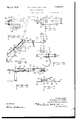
taken through the beam structureis disposed' for attachment to the tractor, as indicated by the dotted lines in vFigure 1, and showing the bracket and hook is a plan view on an enlarged scale, of the forward portion of the diagonal when the wagon is in its rearmost position, thev'wagon tongue being shown fragmentarily, the position of the extension member when disposed to permit attachment of a draft animal to the wagon being indicated by dotted lines. Y
Figure 5 is a section taken substantially on line---5 of Figure 4;
vFigure 6 is a section taken substantially on line 6-6 of Figure 4;
, Figure 7 is a section taken substantially on line 7--7 of Figure 1.
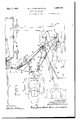
We have illustrated 'for connecting a wagon W, and a corn harvester H, to a tractor T, and to each other.
Our draft connection is particularly adapted l ourinvention as usedA it is to be understood that it is also adapted connection The draft member'2 is of `and, comprises angle side rails'll and 12 con- A 1 nected adjacent thier forward ends by aplatej 1 3. vThese-rails are connected byv trusses andl usset pla-tes,L certainv of" these trusses, des- 1. l
ward arm 'of clev1s33',-wh1ch 1s extended for for-use in connecting two vehicles or implements to a tractor in rear of and at opposite sides thereof, and is vnot restricted to use with a corn harvester and a wagon, which are illustrated by way of example. The corn harvesterv isl illustrated semi-diagrammatically and comprises a laterally extending elevator 1, whichservesto discharge the ears of corn,`
f which have been removed from the/stalks` and husked in a known manner, into the Wagl on W. A draft member 2` extends forward'- ly fromfthe harvester andI is .secured thereto, at 3 fand 4,- in a suitable manner. Atfits forward end,the member 2 is pivoted to drawbar '5 of the tractor on a'horizontal axis, in a it suitablejnanner as by meansof a pin 6 passinglthrou'ghthe forwa rd end of member 2 and throughaloop7 at the rearward'end of the draw bar,.thisloop being normally vclosed by aboltS.. 1 l I' forward end, at 9, vand is secured tof; aU-shapjedrack" 10. carried vby the tractor- .5 This ,.racltgis" provided with a 'pluralitylfof spaced openin'gsby means of which the drawbar may be a'djustably secured to the rackby'l inserting' a pin through an opening inthe bar f andfthrough aselected opening of the rackg'j Thelmanne'rlof securing the draw-bar to thev Y tractor is known in the art and need notbe Villustrated' nor described in greater detaiL- The members 2 and 5 providea direct drawf between the harvester H and the j .ignated 14 and 15 being secured to a trianmoreclearly .gul-ar gusset platejlf which is suitably sel cured to rail l11 and vprojects laterally and' Loutwardly:beyondthis rail. As will be noted.. from Figure3,'the 'outer portion .of gusset plate` 16 isbent' downwardly and then outwardly to provide an. L-shaped brack- 59 etA 17, the lower horizontal arm of which is' disposed .ip preciably below.l the body. portion of pla'te 16. f f l A diagonal ystructure `1 ly from the draft member 2'and has its forl" ward end E suitably connected to .steering 18 extends forwardtongue 19 of the wagon. This diagonal structure comprises a beam .20 which is pivotally v mounted, at its rearward end, on the horizon,-
6.6 tal'arm ofbracket 17 bymeans ofa .pivot bolt 21 which passes through the terminal f portions of straps 22 suitably shaped and se-l cured aboutv the end portion of beam 20 at the upper and lower facesthereof.
T e arms are provided, at their outer ends, with'a series'of alignedopening's 31 for reception of a pinj32. provided at its upper endg, with an angularly ydisposed st-opnger. This f.; fprovides means for :adjusting the pln to corv respond tothe width of the portion of the 'which the member 23 isfat-f tached..
' A clevis S3-is or `'otherwise A.suitabl 4secured to the forward end efthe beam 20.
brace rod'34 issuitably secured to the forrearward end'of beam 20'and is suitably secured thereto asY by means of a bolt 36. A.
between two fingers 38o of apair of plates .'38'whch1seat on l`the upper'v and under faces of beam'20, the fingers .being secured together e by a bolt 39..V The rodl is under' tension 1g( and serves'vto bracethe beam'20 against .rearf ward stresses inia-fknownemanner. l
ssg
I si.
` turnbuckle 37 is provided in the rod 34 for tensioning. the same. At a p oint disposed `forwardly''of turnbuckle 37, rod 34.- ,passes 'A strap .40' extends 'forwardly frorii i 20 and-fis secured, at' its forward end, toa
of openingsvffrireceptin 'of the bolt,.and
. this linkis also proi'ided, at its rearward end I portion, with a longitudinally extending series of y'openings 44 for reception of vzo - hook is adapted for reception of a ring 49 a bolt 45 passing through strap 40,the tongue and link 41.
We have illustratedthis bolt as also passing through the two plates 38 for securing them to the beam. By reference to Figure 1, it will be noted that the beam-is provided with a series of openings 46spaced apart lengthwise thereof. The provision of the v opening in link 41 provides simple `and eilicient means for adjustin the effective length of this link to suit conditions. The openings 46 in the beam 2O are of value as providing l means for adjusting the point of connection wagon acts on the harvester. lof the wagon will varyjconsiderabg in accordance with conditions,'-such as di erenceslin the ground surface',f tlie condition ofthe taken into consideration.l By providin 1- v adjustable connectionbet'ween the dra t "'-41 and the beam 20, itis possible to balance the side draft of the wagon against the side :draft of the harvester in such manner that between the beam and the link.v In this draft connection the side draft of the wagon counter-acts the side draft of the harvester and the point of connection between the beam and the links 41 is the fulcrum point of the lever' through which the side draft of the The side draft soil, and otherconditionswhich have to be this link the one counteracts the other, and the tractor 'Y T is not subjected to objectionable side draft from either the wagon or the harvester.l This.
is advantageous as facilitating operation vof the entire assembly and assuring proper tracking of the harvester, and the wagon so that the harvester will follow the corn row accurately and the wagon will'v be properly l to the beam.
- rate bolt is employed for securing the plate disposed for reception of the ears vdischarged from the elevator 1.
can be employed for When however, the bolt 45 is removed and a sepa- A 38 tothe beam. 1
'- Draft link 411 is secured'at its forwardnend,
I at 47, to rack 10 of the tractor, in a suitable vides a draft connection-between beam 20 and' manner, as by means of a pin-or bolt insertedthrough the link and through a. selected one of the openings ofthe rack. .1 This link prothe tractor.` A hook 48 is secured to link 41 in-advance-of the series of openings 43. This at the forward end of 'a draft chain 50. This chain passes through an eye 51 pivotally mounted on a vertical axis, as by means of pivot pins 52, between arms 25 and 2G of the extension member 23. These pins are carried bylugs projecting forwardly from eye 51 and have their outer ends threaded ,for reception of securing nuts. The eye 51 is of proper interiordiameter to permit free sliding f v l 'and aft positions so With'the strap 40 and link 41 attached to' beam 20 at the. point illustrated, the bolt 451 securing the plates ,3S the strap and the link'4 are attached to the beam at some other point,
through beam 20 and movementv therethrough of chain 50, but is of less interior diameter than the 'exterior diameter of ring 49. The rearward end of chain 50 is suitably secured to the wagon.g-
This may be accomplished by inserting .the usual king ing the dou le tree to'tongue 19, through a ring or link at the rearward end of the chain, this, pin also being inserted through the ton ue in a knownmanner.
ith the wagon in its forward position illustrated in Figure 1, the chain 50 provides l a draft connection betweenthe wagon and `tl'ie'extension member, in that the eye provides an abutment' or bearing for the chain, as well as between the wagon and the link 41,
' 'When the wagon W, is in its most forward position illustrated in full lines in Figure 1, chain 50 is attached tohook 48, as illustrated 'in lfull lines. When the wagon is in its rearmost position', the chain is released from the hook and the ring'49 contacts eye 51, thus providingadirect draft connection between the wagon 'and the diagonal structure. To t adjust the wa on in an intermediate fore and aft position,f-a pin may be inserted through arms 25 and 26 of the extension member, this pin being also inserted through a selected one of the links of the chain. Such a pin, designated 54, is carried in aligned openings throu h the arms of the extension member. In this manner, the point of connection be-` ture can readily be adjusted in accordance with variation in the fore and aft positioiisnfi thewagon. This is advanta ing it possible to quickly an plurality levelin eous as rendereasily position the wagon in any one of a plurality of fore y that the ears may be dis- -charged from elevator 1 into 4the -wagon at a' aev 'tween the draft chain and the diagonal struc- `ilus of points lengthwise thereof, suc'` f cessively, thus avoiding anyV necessityjforr the load b hand which is necessary when t e ears are isclia'rged into the wagon 'at a single point only, or even at the front and rear thereof only.
The pin 54 is also available 'for insertion through an opening 55 in arm 25 of extension member 23, and through openings extendin the lower arm 26 an ali the extension member 23 against forward 'nt' gned with opening'55. When -positioned l in the opening 55, the pin 54 serves to holdmovement about its pivot. This is not necessary when operating on level ground or when .traveling up hill, but it is necessary when izo' . '0* 1n 53, normally used for attach- 7 Y singletrees, the ki itjma'ybereplaced by` anempty rWagon which' f is' drawn into position by: draftanimals at# f after which the extension member 23 is swung forwardly about bolt 24 into approximately theldotted line position of FlgureY 4. This provides ample space atthe tractor side of .tongue '19 for bitching of a draft animal to .th wagon at this side of the vtongue. The draft. nimals are hitched to thefwagon` by meansof the usual .doubletree and'associated n bolt -53 being employed forattaching the dgoubletree to the tongue. Thislirende'rs it4 possible to hitch the draft animalsto theA wagon with a minimum of trou e and 'delay andiwithout any necessity ifting the `positionofthe beam 20. the loaded vvagonv has beenV removed,
Areal,
tachedthereto, afterfwhich the draft animals arel '.unhitched from thefwagon andthe ex tensionmember 23and chain 50 are again at. tacked tothe wagon` in the manner previously `described 1.
.tractor .in substantial alignment therewith.
, l`cause the'harvester and thetractor when so relatively disposed Vyoc'cu y less road space 'tha'nz would bethe case i Atheharvesterwere 'fjdisposed an appre'ciabledistance to one side4 l v I Referring moregparticularly. to Figures 2,"1 ,f 'v .the tractor betterfwhen disposedjin substanf of thev tractor; secondly,`theI harvester trails tialy alignment therewith and `objectionable lateral stresses are avoided. .For'transport-1 l"ing thegharvester-H,beam 2O is swung into i -po'sitidn to` extend beneath -draft member.: 2
` and 'forwardlythereof,I as indicated by dot-i 'ted lines. Thelink 41,"which has previously beenfjdetached fromv thel tractor T, is turned*- finto-the Adottedline position of I*`.igui'e1,andf4 hasfits 1*;earwardend-securedto a -bracket56,
."suitably secured to the frame-of harvester H,
iatlthe" opposite side of draftl'uemberv 2l from. gusset plate 16. For securing thelink to the bracket. 56,-'vpin 54 may be employed. .y .The lextension. member '23 is then vturned into the dotted linev position of .Figure 1,.an'd' draft chain 50 is looped about bracerod 34 andhas lv33, to draw-barl 5.of tha-tractor, this drawbar being disposed fore and aft of thetracand highly eicient hitch between the tractor and the harvesterfwhereby the tractor' pulls theharves'ter in aligmnent therewith.
Referring to Figure'2, it will be noted that `-tachment to the tractor.
A U-shapedy bracket 57 is secured a bolt x58 about rail 12 of` draft member 2. f The upf per-.arm yof'this bracket carries a projection'- 59 to ywhich a hook 60 is pivoted at 61 on a l nf/When `etranslliiuiting'I.the harvester fro'mbne scene of operations to another, it fis de-y sirable .that the' harvester trail behind the' 'its ends'secured tof-this extension members` 1 Beam 20is then attached, by means of clevis,
horiziontal axis.` This hook is adapted for engagement about and beneath beam 2O .for securing draft member 2te th'ebeam. f In moving the beam into position for attachment to the tractor,'it is swung in the direction of the harvester-H, beyondthe dotted line position of Figure-.1. During this movement of'the beaml hoolrO. is turned upwardly into the dotted vline positioneof Figure 2, and is then swung downwardly.v into the` full line position ofthisligure, after whichthe ,beam 2O is vmoved in a reversed direction so as to viit draftmember 2 to the vbeaminsuch manner as to 'besupporte'd thereby jand vprevent. objectionable fore and vaft tipping ofl the har-l vester H. In. thisy manner,e the harvester is suitably supported, in transport, so as to hold the point-seatv the. forward endo shoes 62 out ofy contactwithithe ground surface, these `points being desigpated 63.- Thisis advan` tageous Ias elimin Yng* possible injuryto thef; pomtsof-theharvester shoes.., "f
4,'and 5, a resilient supporting shoe 64 isv providedI 'adjacent the forward end of beam 20-`r for supporting the' same.- This shoe may con.
veniently be formedy from a suitable .length ofxstra'p iron-'bent intojarcuate shape-and riv-V f with an angularly'disposed flange l.'66 which contactsY the forward facefof beam20, this plate being secured to the'beam. in a suitable mannen as by means of, a bolt 67.- The shoe 64 serves as a' groundy contacting memberfor supporting theforward end of beam 20 and,
to a certain extent, tonguel 19 of the'wagon. V.When the harvester is stored, beam 2O is disposed beneath and secured to draft" member 2 as `indicated in dotted lines in Figure 1 and Vas above described. vAt this time/the shoe 64 i' serves 'tosupportthe beam and draft-member`v .and to., hold'. points 63-of the harvester out Jos .of -eontact'with.the-supporting surface."
v l f-When the beam 20is`, ii''the -full line position 55; to'rat this time. This provides a convenienteY of Figure 1 and is connected toztongue 1#y of the greater part of the'weight of tongue 19 oli" ot the extension member 23. This means comprises a' hook 68 whichengages about and' beneath tongue 19 and has its upper end secured .toa ytension spring 69,;the upper end of which vis secured to the wagon body in a suitable manner, as by means of a hook 70.
and an agricultural implement and a wagon disposed to one side thereof, a draft member connecting the tractor and the implement, a
diagonal structure connecting the said implement and the wagon, a link connecting said structure to the tractor, a draft member connected to the wagon, and means for releasably attaching the draft member to said link, or to said structure, optionally, to accommodate variation in the fore 4and aftposition of the wagon.
3. In adraft connection between a tractor and an agricultural implement and a wagon 'disposed to one side thereof and comprising a steering tongue, a draft member connecting the implement and the tractor, a diagonal structure comprising a beamconnected at its rearward end to said member and an extension member proj ecting'from the forward end of the beam and connected to said tongue, a
for securing bearing member-"carried by said extension member, a flexible draft member secured at its rearwardg-'end to the wagon, a link connecting the v'beam and the tractor, and means i the forward end of said flexible member tothe link or the extension member, optionall ,the iexible member being secured tothe andbearing on said bearing member in the'forward position of the wagon, the flexible member being released from the link and secured tothe extension member in the rearward position ofthe wagon, whereby variation in the fore and aft position of the wagon is accommodated. i
4. In a draft connection between a tractor 'and an agricultural implement and a wagon disposed to one side thereof and having a steering tongue, a draft member connecting the implement and the tractor, a diagonal structure connecting said member and the' wagon, A ture and the tractor, and a draft connection a draft connection between said struc between the diagonal structure and thewagon, said diagonal structure comprising an extension member detachably secured to the,y tongue and mountedfor separate movement:
independent of said diagonal structure away from .the tongue when released therefrom and into position to leave a space at the adjacent sidey of the tongue for bitching of a.
draft animal to the wagon. y
5. In a draft connection between a tractor and an agricultural implement and a wagon disposed to one side thereof and having a steering tongue, a draft member connecting the implement and the tractor, a diagonal structure comprising a beam connected at its rearward end to the implement and an extension member at the forward end of the beam and detachably connected to the tongue, said extension member being mounted on the beam for relative movement away fromv the tongue when dctched therefrom, a draft connection between the beam and the tractor, and a draft connection between the wagon and said extension member.
6. In a draft connection between a tractor and an agricultural implement and a wagon disposed to one side thereof and having a steering tongue, a draft member connecting the implement and the tractor, a diagonal structure comprising a beam connected at its rearward end to the draft member and an extension member at the forward end of the beam and detachably connected to the tongue, said extension member being pivoted on the beam for turning movement forwardly away from the tongue when released therefrom, means preventing turning movement of the extension member rearwardly beyond operative position, a draft connection4 between the beam and the tractor, and a draft connection between said extension member and the wagon.
7. In a draft connection between a tractor and an agricultural implement and a wagon disposed to one side thereof and having a steering tongue, a draft member connecting the implement and the tractor, a diagonal structure comprising a beam connected atlits rearward end to the draft member and an extension member atl the forward end of the beam and detachably connected to the tongue, said extension member comprising a pair of arms pivoted to the beam on a horizontal axis and having rearwardly extending and angularly disposed elements extending along the beam, a stirrup carried by said elements and fitting about the rearward portion of the beam and preventing relative rearward movement` of the extension member beyond operative position, means releas'ably, securing the extension .member of the tongue, a draft connection between the beam and the tractor, and a draft connection between said extension member and the wagon.
8. In draft means for connecting an agricultural implement and a wagon dis ose at one side thereof to a tractor, a dra inember connected to the implement and adapted for connection' to the tractor, a. structure pivoted at its rearward end to the draft member and adapted to be secured at its forward end to the tongue of the wagon in diagonal relation to said member at one side thereof, said structure when released from the wagon tongue being movable on its pivot into position to extend forwardly beyond the draft member in substantial alignment with said implement for attachment to the tractor, and means for providing a draft connection between said structure and the tractor when the structure is in its first position and between said structure and the implement when the structure is in its second position.
9. In draft means for connecting an agricultural implement and a wagon disposed to one side thereof to a tractor, a draft member connected to the implement and adapted for connection to the tractor, a structure connected to said member and movable relative thereto into either one of two-operative positions, said structure in one position extending diagonally forward from one side of the draft member and being disposed for connection to the wagon an(` in its second position being disposed forwardly of the implement and in substantial alignment therewith for attachment to the tractor, and means for connecting said structure to the tractorin its first position and to the implement inwits second position. 10. In draft means for connecting an agricultural implement and a wagon disposed to one side thereof to a tractor, a draft member connected to the implement and adapted for connection to the tractor, a. structure connected to said member and movable relative thereto into either one of two operative positions, said structure in one position extending diagonally forward from one side of the draft member and being disposed for connection to the wagon and in its second position being,
' ldisposed forwardly of the implement and in substantial alignment therewith for attachment to the tractor, means for connecting said structure to the tractor in its first position an'd to the implement in its second position, and means for securing the draft member to said structure when it is in said second position:
' 11. In`I draft means for connecting an avricultural implement and a wagon disposed to one side' thereof to a tractor, a draft member connected to the implement and adapted for connection'to the tractor, a structure pivoted to said member at one side thereof and movable relativeV thereto into either one of two operative positions, said structure in one position extending diagonally forward from said side of the draft member and being disposed for connection to the wagon and in its second position being disposed forwardly of the implement'and in substantial alignment therewith for attachment to the tractor, and means for connecting said struct-ure to the tractor in its first position and to the implement adjacent the other side of theI draft member in its second position.
12. In draft means for connecting an 4agricultural implement `and a wagon disposed to one side thereof to a tractor, a draft member connected to the implement and adapted for connection to vthe tract-or, a structure pivoted to said member at one side thereof and movable relative thereto into either one of two operative positions, said structure in one position extending diagonally forward from said side of the draft member and being disposed for connection to the wagon and in its second position being disposed forwardly beneath the draft member and forwardlyof the implement in substantial alignment therewith for attachment to the tractor` and means for connecting said structure to the tractor in its first position and to the implement adjacent the other side of the draft member in its second position.
13. In draft means for connecting an agricultural implement and a wagon disposed to one side thereof to a tractor, a draft member connected to the implement, a beam pivoted at its rearward end to said member at one side thereof and movable into either one of two operative positions relative to the draft mem- Der, the beam in one position extending diagonally forward from said side of the. draft member and in its second position being disposed forwardly of the draft member for attachment to the tractor and in substantialV alignment with the implement, means for attachingthe forward end kof he beam when in is first position to the wagon, and means providing a draft connection'between the beam when in its first position and the tractor and between the beam when in its second position and the implement.
14. In draft means for connecting an agricultural implement and a wagon disposed to one side thereof to a tractor, a draft member connected to the implement, a beam pivoted at its rearward end to said member at one side thereof and movable into either one of two operative positions relative to the draft member, the'beam in one position extending from said side of the draft member and in its second position being disposed forwardly of the draft member for attachment to the tractor and in substantial alignment with the implement, means for attaching the forward end of thebeam when in its first position to the Wagon, a draft link secured to the beam andI 'adapted for attachment to the tractor in the first position of the beam,
and means for attaching the link to the implement at the other side of the draft member in the second position of the beam.
l5. In draft means for connecting an agricultural implement and a wagon V'disposed to one side thereof to a tractor, a draft meinber connected to the implement, a beam pivoted at its rearward end to said member at one side thereof and movable into either one of two operative positions relative to the draft member, the beam in one position extending diagonally forward from said side of the draft member and in its second posidiagonally forward 4 llt) tion being disposed forwardly of the draft member' for attachment to the tractor and in substantial alignment with the implement,
means for attaching the forward end of the beam when in its first position tc the wagon, a draft link piroted to the beam and adapted for attachment to the tractor in the nrst position of the beam, means for attaching the link to the implement at the other side of the draft member in the second position of the beam, said beam in its second position extending beneath and across the draft member, and means for securing the draft member to the beam. when the latter is in said second position.
I6. ln draft means for connecting an agricultural implement and a wagon disposed to one side thereof to a tractor, a draft member secured to the implement, a structure comprising a beam pivoted at its rearward end to the draft member and movable about its pivot to a position beneath the draft member, said beam in its latter position being connected to the tractor to serve as an auxiliary means for transmitting draft to the implement, and a-supporting member depending 'from the beam and disposed to contact a supporting surface to support the beam and the superposcd draft member when the beam is free from the wagon and the tractor.
17. ln a draft connection between a traetor and an agricultural implement and a wagon disposed to one side thereof, a draft member connecting the tractor and the implement, a diagonal structure connecting said member and the wagon, a, link connecting the structure to the tractor, a guide member carried by said diagonal structure, a draft chain passing through the guide member and secured at its rearward end to the wagon, means for releasably securing the forward end of the chain to the link, and means for adjustably securing the chain to the diagonal structure for varying the effective length of the chain.
18. In an agricultural machine embodying a tractor and two implements adapted to be drawn by the tractor in side by side relationship, a draft connection between the tractor and the implements comprising a member connected to one of the implements and adapted to be connected directly to the tractor and a second member pivotally connected with the first member and adapted to transmit draft to the second implement, said sec-I ond member being adapted to swing about its pivotal connection with said first member to a point substantially directly forward of the first implement whereby the tractor can be connected to the forward end of said second draft member to draw the first implement when the second implement has been disconnected.
19. In an agricultural machine embodying `a tractor and two implements adapted to be drawn by the tractor in side by side relationn ship, a draft connection between the tractor and the implements comprising a forward` ly and laterally extending member connected to one of the implements and adapted to be connected to the tractor and a second member pivotally connected with the first member and adapted to transmit'draft to 'the second implement, said second mem-her being adapted to swing about its pivotal connection with said first member to a point substantially directly forward of the first implement, and means for rigidly holding said second member with respect to said first implement in said latter position, whereby the tractor' can be connected to the forward end of said second draft member to draw the first implement when the second implement has been disconnected.
20. In a draft connection between a tractor and an agricultural implement and a wagon disposed to one side thereof, a draft member connecting the tractor and implement, a diagonal structure connectiner saiddraft member to said wagon or to said tractor, optionally, to transmit draft to the wagon or implement, said diagonal structure when connected to the tractor being disposed below said draft member for supporting it while transmitting draft to the implement.
21. In a draft connection between a tractor and an agricultural implement and a wagon disposed to one side thereof, a draft member connecting the tractor and the implement, a diagonal structure between said implement and wagon, and means for connecting the diagonal structure to said draft member for transmitting draft to the wagon in normal operation of the implement, said diagonal structure vbeing adapted to pivot on said means toa position beneath said draft member, `whereby said diagonal member may be connected to the tractor to support said draft member while transmitting forward draft thereto.
In witness whereof, we hereunto subscribe our names this 3rd day of July, 1929.
'IVILBUR J. COULTAS.
CARL J. FREDERIKSEN.
Priority Applications (1)
| Application Number | Priority Date | Filing Date | Title |
|---|---|---|---|
| US376561A US1856468A (en) | 1929-07-08 | 1929-07-08 | Draft connection |
Applications Claiming Priority (1)
| Application Number | Priority Date | Filing Date | Title |
|---|---|---|---|
| US376561A US1856468A (en) | 1929-07-08 | 1929-07-08 | Draft connection |
Publications (1)
| Publication Number | Publication Date |
|---|---|
| US1856468A true US1856468A (en) | 1932-05-03 |
Family
ID=23485497
Family Applications (1)
| Application Number | Title | Priority Date | Filing Date |
|---|---|---|---|
| US376561A Expired - Lifetime US1856468A (en) | 1929-07-08 | 1929-07-08 | Draft connection |
Country Status (1)
| Country | Link |
|---|---|
| US (1) | US1856468A (en) |
-
1929
- 1929-07-08 US US376561A patent/US1856468A/en not_active Expired - Lifetime
Similar Documents
| Publication | Publication Date | Title |
|---|---|---|
| US6282875B1 (en) | Agricultural vehicle and implement with wheels | |
| US3835629A (en) | Crop conditioners | |
| US1941670A (en) | Harvester hitch | |
| US1856468A (en) | Draft connection | |
| US3841504A (en) | Bale loader | |
| US2335942A (en) | Means for coupling implements to tractors | |
| US2092597A (en) | Tractor draw-bar | |
| US2769295A (en) | Hitch device for tractor drawn agricultural implement | |
| US2520743A (en) | Break-back implement attachment for tractors | |
| US3039541A (en) | Implement attachment for tractor | |
| US2544925A (en) | Hitch for joining harvester and a wagon to a tractor | |
| US1865786A (en) | Draft device for mowers | |
| US1882868A (en) | Wagon hitch | |
| US3003790A (en) | Implement hitch | |
| US2853315A (en) | Laterally adjustable drawbar for tractors controlled by the front steering wheels of the tractor | |
| US1646342A (en) | Hitch | |
| US1616299A (en) | Plow hitch | |
| US1632145A (en) | Hitch | |
| US2592866A (en) | Implement draft connection | |
| US1769102A (en) | Tractor hitch for dump rakes and the like | |
| US1090338A (en) | Bundle-carrying attachment for grain-harvesters. | |
| US3529411A (en) | Side delivery rake | |
| US1935987A (en) | Draft connection | |
| US2201660A (en) | Implement hitch | |
| US962701A (en) | Harrow attachment for sulky-plows. |