US1856467A - Liquid cooler - Google Patents
Liquid cooler Download PDFInfo
- Publication number
- US1856467A US1856467A US391233A US39123329A US1856467A US 1856467 A US1856467 A US 1856467A US 391233 A US391233 A US 391233A US 39123329 A US39123329 A US 39123329A US 1856467 A US1856467 A US 1856467A
- Authority
- US
- United States
- Prior art keywords
- pipe
- liquid
- cooler
- horizontal
- pipes
- Prior art date
- Legal status (The legal status is an assumption and is not a legal conclusion. Google has not performed a legal analysis and makes no representation as to the accuracy of the status listed.)
- Expired - Lifetime
Links
- 239000007788 liquid Substances 0.000 title description 50
- 239000003507 refrigerant Substances 0.000 description 11
- 238000007599 discharging Methods 0.000 description 9
- 238000004891 communication Methods 0.000 description 4
- 230000006854 communication Effects 0.000 description 4
- 238000010276 construction Methods 0.000 description 3
- 230000001105 regulatory effect Effects 0.000 description 2
- 239000006096 absorbing agent Substances 0.000 description 1
- 230000001276 controlling effect Effects 0.000 description 1
- 238000001816 cooling Methods 0.000 description 1
- 235000013365 dairy product Nutrition 0.000 description 1
- 230000005484 gravity Effects 0.000 description 1
- 238000013022 venting Methods 0.000 description 1
Images
Classifications
-
- F—MECHANICAL ENGINEERING; LIGHTING; HEATING; WEAPONS; BLASTING
- F28—HEAT EXCHANGE IN GENERAL
- F28D—HEAT-EXCHANGE APPARATUS, NOT PROVIDED FOR IN ANOTHER SUBCLASS, IN WHICH THE HEAT-EXCHANGE MEDIA DO NOT COME INTO DIRECT CONTACT
- F28D3/00—Heat-exchange apparatus having stationary conduit assemblies for one heat-exchange medium only, the media being in contact with different sides of the conduit wall, in which the other heat-exchange medium flows in a continuous film, or trickles freely, over the conduits
- F28D3/02—Heat-exchange apparatus having stationary conduit assemblies for one heat-exchange medium only, the media being in contact with different sides of the conduit wall, in which the other heat-exchange medium flows in a continuous film, or trickles freely, over the conduits with tubular conduits
Definitions
- Another object of the invention 1s to provide a cooler of the type and character mentioned embodying means for maintaining in the lower header pipe and vertical pipes a refrigerant liquid at approximately a constant level, and means for maintaining a constant pressure and temperature in the cooler.
- Another object of the invention is to provide a cooler of the type and character mentioned having means for causing all or approximately all of the liquid to flow downwardly along the vertical pipes by preventing the liquid from dripping from the upper header.
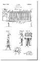
- Fig. 1 is a side elevation of my improved cooler.
- Fig. 2 is an end elevation, with the parts ig section, approximately on the line 2--2 of i 1.
- Fig. 3 is a vertical sectional view ofy the upper portion of the cooler approximately on the line 8-3 of Fig. 4.
- Fig. 4 is a side elevation of the upper poition of the cooler shown in Fig. 3.
- Fig. 5 is a detail of a float lcontrol valve included in the invention.
- the cooler is mounted on a supporting .frame-Work 1 of any appropriate construction and comprises, at one end, an upright end member 2 and at the opposite end an upright member 3.
- These endy members constitute supports ⁇ tor the horizontal header pipes and also constitute end Walls oi an enclosure for the cooler proper.
- the upper header comprises a horizontal pipe l supported near the upper end of the end members 2 and 3, and the lower header comprises a horizontal pipe 5 supported near the lower end of the end members 2 and 3.
- These horizontal pipes 4 and 5 are connected by a longitudinal series of vertical pipes 6,
- the pipes 6 are of less diameter than the pipes fi and 5.
- the pipe a has communication through a pipe section 7 with a liquid trap 8 from the lower end of which the pipe 9 opens into a fitting 10 having communication with the adjacent pipe 5 through a pipe section 11.
- a pipe 12 extends to an absorber or compressor (not shown) and is equipped with a back pressure l valve device 13 of any known or appropriate construction which acts to hold a constant. pressure and thereby maintain approximate-t lv a constant temperature in the cooler but oes not prevent passage of the vaporized refrigerant therethrough to the receiver when the pressure in the cooler exceeds the predetermined amount of pressure.
- a return pipe 14 for the condensed refrigerant has communication through a valve housing 15 and a pipe 16 to the fitting 10 and thence through the pipe 11 to the ipe 5.
- the valve housing 15 is at the end o an arm 17 which extends from a oat chamber 18.
- the upper portion of the float chamber 18 has com munication with the upper'portion of the trap 8 through a pipe 19.
- a float 20 in the float chamber 18 is operatively connected With a valve 21 controlling the opening into the pipe 16 from the valve housing 15.
- a pipe 22 opens from the lower end of the float chamber 18 into'the pipe 9.
- the distributor device comprises a pipe 23 mounted in supports 24 on the end members 2 and 3 and having through its lower side numerous outlet openings 25. These openings 25 constitute a longitudinal series of openings immediately above the pipe 4 so that anyA liquid discharged through said openings 25 is discharged onto the upper portion of the pipe 24 and thereby spread and caused to flow downwardly along the lopposite sides of said pipe 24. A portion of.
- this liquid passes directly from the pipe 4 to the vertical pipes 6.
- the remaining portion of this liquid passes from the pipe 4 to the distributor strips 26 located between and contacting with the upper ends of the pipes 6 and also contacting with the lower side of the pipe 4 and having on their opposite sides downwardly diverging grooves 27. That portion of the liquid ilowingfrom the pipe 4 onto the distributor strips 26 is conducted bythe grooves 27 to the respective pipes 6 so that all of the liquid is caused'v to flow downwardly along said pipe 6 and is thereby subjected to the cooling action of the refrigerant.
- a supply pipe 28 opens into a pipe 29 supported longitudinally within the pipe 23 and spaced therefrom. with the pipe 23 and has therethrough a longitudinal series of holes 30 from which the liquid is discharged into the pipe 23.
- the liquid to be cooled is admitted to the pipe 29 from the pipe 28. From the pipe 29, the liquid to be cooled passes from the openings 30 into the pipe 23 and thence through the openings 25 ontothe upper side of the pipe 4 approximately throughout the length of said pipe 4.
- a cooler of the character described comprising a longitudinal series of vertical pipes, horizontal pipes opening into the upper and lower ends of the vertical pipes respectively, a pipe system for maintaining a liquid refrigerant filling said horizontal pipe that opens into the lower ends of said vertical pipes and filling said vertical pipes to a constant level below said horizontal pipe that opens L into the upper ends of said vertical pipes, moans for dischargingthe liquid to be cooled upon the upper side of said upper horizontal a pipe system for maintaining al liquid iefrig-,
- a cooler of the characterdescribed comprising a series of vertical pipes, a horizontal pipe opening into the upper ends of said vertical pipes, means for discharging liquid along the upper side of said horizontal pipe, and means for preventing the liquid from dripping from said horizontal pipe and causing the liquid to flow downwardly along said vertical pipes.
- a cooler of the character described cornprising a series of vertical pipes, at horizontal pipe openinginto the upper ends of said vertical pipes, means for discharging liquid along the upper side of said horizontal pipe,
- a device for regulating the supply of liquid to said dischargmg means means for preventing the liquid from dripping from said horizontal pipe and causing the liquid to flow dou'nvardly along said vertical pipes, a horizontal pipe opening into the lower ends of said vertical pipes, and means 'for receiving liquid dripping from said last named horizontal pipe.
- a cooler ot the character described comprising tivo parallel spaced horizontal )ipes supported one above the other, a series oi vertical pipes having their upper ends opening into the upper one ot said horizontal pipes and their lower ends opening into the lower one of said horizontal pipes, a pipe supported above said upperhorizontal pipe and having holes for discharging liquid. onto said upper horizontal pipe, and means in said last named pipe for distributing the liquid in said last named pipe for discharge through said holes.
- a cooler of, the character described comprising two horizontal pipes spaced one above the other, a series ot vertical pipes having their upper and lower ends opening into said horizontal pipes respectively, means for maintaining a liquid refrigerant completely filling the lower one of said horizontal pipes and iilling said vertical pipes to approximately a constant level, a discharge pipe supported above the upper horizontal pipe and having holes for discharging liquid onto said upper horizontal pipe, and a distributor pi pe in said discharge pipe having holes for discharging liquid into said discharge pipe for discharge therefrom as aforesaid.
- a cooler ot the character described comprising a series of vertical pipes. a horizontal pipe opening into the upper ends of said vertical pipes, a discharge pipe supported above said horizontal pipe and having holes for discharging liquid onto the upper side of said horizontal pipe, and a distributor device in said discharge pipe for distributing the liquid in said discharge pipe for discharge through said holes.
- a cooler of the character described coms prising a. series of vertical pipes, a horizontal pipe opening into the upper ends of said vertical pipes, a discharge pipe supported above said horizontal pipe and having holes for discharging liquid onto the upper side of said horizontal pipe, a distributor device in said discharge pipe for distributing the liquid in said discharge pipe for discharge through said holes, means for maintaining a refrigerant in said vertical pipes, and means for pre.- venting the liquid from dripping from said horizontal pipe and for causing the liquid to flow downwardly along said vertical pipes.
Landscapes
- Engineering & Computer Science (AREA)
- Physics & Mathematics (AREA)
- Thermal Sciences (AREA)
- Mechanical Engineering (AREA)
- General Engineering & Computer Science (AREA)
Description
May 3, 1932.
R. COPP LIQUID COOLER Filed Sept. 9, 1929 Figli?,
Patented May 3, 1932 aaai PATENT ortica RALPH COPP, F ST. LOUIS, MISSOURI, ASSIGNOR TO PEVEIIY DAIRY COMPANY, OF ST.
' LOUIS, MISSOURI, A CGRPORATION QF MISSOURI LIQUID COOLER Application'led September 9, 1929.' Serial No. 391,233.
means for spreading a flow of liquid'over said pipes so that the liquid Will low by gravity to a Withdrawal device.
Another object of the invention 1s to provide a cooler of the type and character mentioned embodying means for maintaining in the lower header pipe and vertical pipes a refrigerant liquid at approximately a constant level, and means for maintaining a constant pressure and temperature in the cooler.
v Another object of the invention is to provide a cooler of the type and character mentioned having means for causing all or approximately all of the liquid to flow downwardly along the vertical pipes by preventing the liquid from dripping from the upper header.
Other objects appear from the following description, reference being made to the accompanying drawings in which- Fig. 1 is a side elevation of my improved cooler.
Fig. 2 is an end elevation, with the parts ig section, approximately on the line 2--2 of i 1.
Fig. 3 is a vertical sectional view ofy the upper portion of the cooler approximately on the line 8-3 of Fig. 4.
Fig. 4 is a side elevation of the upper poition of the cooler shown in Fig. 3.
Fig. 5 is a detail of a float lcontrol valve included in the invention.
The cooler is mounted on a supporting .frame-Work 1 of any appropriate construction and comprises, at one end, an upright end member 2 and at the opposite end an upright member 3. These endy members constitute supports `tor the horizontal header pipes and also constitute end Walls oi an enclosure for the cooler proper.
The upper header comprises a horizontal pipe l supported near the upper end of the end members 2 and 3, and the lower header comprises a horizontal pipe 5 supported near the lower end of the end members 2 and 3. These horizontal pipes 4 and 5 are connected by a longitudinal series of vertical pipes 6,
the upper ends of which open into the pipe l and the lower ends of which open into the pipe 5. The pipes 6 are of less diameter than the pipes fi and 5.
The pipe a has communication through a pipe section 7 with a liquid trap 8 from the lower end of which the pipe 9 opens into a fitting 10 having communication with the adjacent pipe 5 through a pipe section 11. From the upper end of the trap 8 a pipe 12 extends to an absorber or compressor (not shown) and is equipped with a back pressure l valve device 13 of any known or appropriate construction which acts to hold a constant. pressure and thereby maintain approximate-t lv a constant temperature in the cooler but oes not prevent passage of the vaporized refrigerant therethrough to the receiver when the pressure in the cooler exceeds the predetermined amount of pressure. A return pipe 14 for the condensed refrigerant has communication through a valve housing 15 and a pipe 16 to the fitting 10 and thence through the pipe 11 to the ipe 5. The valve housing 15 is at the end o an arm 17 which extends from a oat chamber 18. The upper portion of the float chamber 18 has com munication with the upper'portion of the trap 8 through a pipe 19. A float 20 in the float chamber 18 is operatively connected With a valve 21 controlling the opening into the pipe 16 from the valve housing 15. A pipe 22 opens from the lower end of the float chamber 18 into'the pipe 9. Thus, it is ap-' paient that when the amount of liquid refrigerant in the cooler exceeds a predetermined inaximum and rises vthrough the pipe 11, the fitting 10 and the pipe 22 to a predetermined height in the float valve chamber 18, the float 2G will be raised and the valve 21 will be closed so as to prevent any additional amount et refrigerant liquid from passing through the pipe 16 into the cooler. This does not interfere with the operation of the valve device 13 to permit passage of va porized refrigerant Jfrom the cooler to an ahsorher or compressor, When the amount of reduced approximately to the line 22a (Fig.
1) the lloat 20 will open the valve 21 and permit an additional amount of liquid refrigerant to enter the cooler,
The distributor device comprises a pipe 23 mounted in supports 24 on the end members 2 and 3 and having through its lower side numerous outlet openings 25. These openings 25 constitute a longitudinal series of openings immediately above the pipe 4 so that anyA liquid discharged through said openings 25 is discharged onto the upper portion of the pipe 24 and thereby spread and caused to flow downwardly along the lopposite sides of said pipe 24. A portion of.
this liquid passes directly from the pipe 4 to the vertical pipes 6. The remaining portion of this liquid passes from the pipe 4 to the distributor strips 26 located between and contacting with the upper ends of the pipes 6 and also contacting with the lower side of the pipe 4 and having on their opposite sides downwardly diverging grooves 27. That portion of the liquid ilowingfrom the pipe 4 onto the distributor strips 26 is conducted bythe grooves 27 to the respective pipes 6 so that all of the liquid is caused'v to flow downwardly along said pipe 6 and is thereby subjected to the cooling action of the refrigerant.
A supply pipe 28 opens into a pipe 29 supported longitudinally within the pipe 23 and spaced therefrom. with the pipe 23 and has therethrough a longitudinal series of holes 30 from which the liquid is discharged into the pipe 23.
From the pipe 5 the cooled liquid drops into a trough comprising side walls Sl'and a bottom wall 32 which inclines downwardly from which each end of its intermediate portion where said trough opens into a withdrawal pipe 38.
In operation, the liquid to be cooled is admitted to the pipe 29 from the pipe 28. From the pipe 29, the liquid to be cooled passes from the openings 30 into the pipe 23 and thence through the openings 25 ontothe upper side of the pipe 4 approximately throughout the length of said pipe 4. The
liquid flows downwardly across the oppositie pipe 5 and thence into the receiving trough at the lower end of the cooler. The liquid is withdrawn from the trough through the pipe 33. An approximately constant temperature ismaintained in the cooler by the ar-kr The pipe 29 is concentric rangement shown generally in Fig. l and described above.
From the foregoing, it is now apparent that my invention obtains all its intended objects in a highly eiiicient and satisfactory manner. The construction and arrangement may be varied widely within equivalent limits without departure from-the nature and principle thereof. I do not restrict myself in any unessential respects, but what I claim and desire to secure by Letters Patent is:
l. A cooler of the character described comprising a longitudinal series of vertical pipes, horizontal pipes opening into the upper and lower ends of the vertical pipes respectively, a pipe system for maintaining a liquid refrigerant filling said horizontal pipe that opens into the lower ends of said vertical pipes and filling said vertical pipes to a constant level below said horizontal pipe that opens L into the upper ends of said vertical pipes, moans for dischargingthe liquid to be cooled upon the upper side of said upper horizontal a pipe system for maintaining al liquid iefrig-,
erant filling said horizontal pipe that opens into the lower ends of said vertical pipes and filling said vertical pipes to a constant level below said horizontal pipe Vthat opens into the upper ends of said vertical pipes, means for discharging the liquid to be cooled upon the upper side of said upper horizontal pipe, a device tor regulating the supply of liquid to said discharging means, means -for preventing the liquid from dripping from said upper horizontal pipe and for causing the liquid to flow down said ver-tical pipes, and a receptacle for receiving the liquid dripping lfrom said lower horizontal pipe.
3. A cooler of the characterdescribed comprising a series of vertical pipes, a horizontal pipe opening into the upper ends of said vertical pipes, means for discharging liquid along the upper side of said horizontal pipe, and means for preventing the liquid from dripping from said horizontal pipe and causing the liquid to flow downwardly along said vertical pipes.
4. A cooler of the character described cornprising a series of vertical pipes, at horizontal pipe openinginto the upper ends of said vertical pipes, means for discharging liquid along the upper side of said horizontal pipe,
a device for regulating the supply of liquid to said dischargmg means, means for preventing the liquid from dripping from said horizontal pipe and causing the liquid to flow dou'nvardly along said vertical pipes, a horizontal pipe opening into the lower ends of said vertical pipes, and means 'for receiving liquid dripping from said last named horizontal pipe. l
5. A cooler ot the character described comprising tivo parallel spaced horizontal )ipes supported one above the other, a series oi vertical pipes having their upper ends opening into the upper one ot said horizontal pipes and their lower ends opening into the lower one of said horizontal pipes, a pipe supported above said upperhorizontal pipe and having holes for discharging liquid. onto said upper horizontal pipe, and means in said last named pipe for distributing the liquid in said last named pipe for discharge through said holes.
6. A cooler of, the character described comprising two horizontal pipes spaced one above the other, a series ot vertical pipes having their upper and lower ends opening into said horizontal pipes respectively, means for maintaining a liquid refrigerant completely filling the lower one of said horizontal pipes and iilling said vertical pipes to approximately a constant level, a discharge pipe supported above the upper horizontal pipe and having holes for discharging liquid onto said upper horizontal pipe, and a distributor pi pe in said discharge pipe having holes for discharging liquid into said discharge pipe for discharge therefrom as aforesaid.
7. A cooler ot the character described comprising a series of vertical pipes. a horizontal pipe opening into the upper ends of said vertical pipes, a discharge pipe supported above said horizontal pipe and having holes for discharging liquid onto the upper side of said horizontal pipe, and a distributor device in said discharge pipe for distributing the liquid in said discharge pipe for discharge through said holes.
8. A cooler of the character described coms prising a. series of vertical pipes, a horizontal pipe opening into the upper ends of said vertical pipes, a discharge pipe supported above said horizontal pipe and having holes for discharging liquid onto the upper side of said horizontal pipe, a distributor device in said discharge pipe for distributing the liquid in said discharge pipe for discharge through said holes, means for maintaining a refrigerant in said vertical pipes, and means for pre.- venting the liquid from dripping from said horizontal pipe and for causing the liquid to flow downwardly along said vertical pipes.
RALPH COPP.
Priority Applications (1)
| Application Number | Priority Date | Filing Date | Title |
|---|---|---|---|
| US391233A US1856467A (en) | 1929-09-09 | 1929-09-09 | Liquid cooler |
Applications Claiming Priority (1)
| Application Number | Priority Date | Filing Date | Title |
|---|---|---|---|
| US391233A US1856467A (en) | 1929-09-09 | 1929-09-09 | Liquid cooler |
Publications (1)
| Publication Number | Publication Date |
|---|---|
| US1856467A true US1856467A (en) | 1932-05-03 |
Family
ID=23545819
Family Applications (1)
| Application Number | Title | Priority Date | Filing Date |
|---|---|---|---|
| US391233A Expired - Lifetime US1856467A (en) | 1929-09-09 | 1929-09-09 | Liquid cooler |
Country Status (1)
| Country | Link |
|---|---|
| US (1) | US1856467A (en) |
Cited By (2)
| Publication number | Priority date | Publication date | Assignee | Title |
|---|---|---|---|---|
| US2538015A (en) * | 1948-01-17 | 1951-01-16 | Dole Refrigerating Co | Liquid cooler |
| US3240265A (en) * | 1962-10-03 | 1966-03-15 | American Radiator & Standard | Refrigeration evaporator system of the flooded type |
-
1929
- 1929-09-09 US US391233A patent/US1856467A/en not_active Expired - Lifetime
Cited By (2)
| Publication number | Priority date | Publication date | Assignee | Title |
|---|---|---|---|---|
| US2538015A (en) * | 1948-01-17 | 1951-01-16 | Dole Refrigerating Co | Liquid cooler |
| US3240265A (en) * | 1962-10-03 | 1966-03-15 | American Radiator & Standard | Refrigeration evaporator system of the flooded type |
Similar Documents
| Publication | Publication Date | Title |
|---|---|---|
| US3171266A (en) | Ice making machine with water distribution means | |
| US1856467A (en) | Liquid cooler | |
| US1790911A (en) | George h | |
| US2147788A (en) | Ebullition-type cooler | |
| US1530077A (en) | Oil and water separating means | |
| US1372135A (en) | Water-cooler | |
| US1471088A (en) | Oil and gas separator | |
| US1596423A (en) | Water-deaerating apparatus | |
| US2039796A (en) | Chilling apparatus | |
| US2069430A (en) | Condenser for refrigerating systems | |
| US1994078A (en) | Refrigerating system | |
| US1894441A (en) | Liquid cooler | |
| US1231088A (en) | Refrigerator. | |
| US1085177A (en) | Evaporative refrigerator. | |
| US2168512A (en) | Air line trap | |
| US1925407A (en) | Refrigerating system | |
| US1958805A (en) | Refrigerating system | |
| US2164974A (en) | Feed water heater and scrubber | |
| US935446A (en) | Condenser. | |
| US1567730A (en) | Refrigerator-cooling means | |
| US1978616A (en) | Liquid cooler | |
| US1470638A (en) | Said jankus | |
| US1907104A (en) | Humidifier | |
| US2286329A (en) | Water heater | |
| US2287600A (en) | Deaerator and feed heater |