US1856464A - Carburetor - Google Patents
Carburetor Download PDFInfo
- Publication number
- US1856464A US1856464A US359096A US35909629A US1856464A US 1856464 A US1856464 A US 1856464A US 359096 A US359096 A US 359096A US 35909629 A US35909629 A US 35909629A US 1856464 A US1856464 A US 1856464A
- Authority
- US
- United States
- Prior art keywords
- carburetor
- air
- passageway
- orifice
- pump
- Prior art date
- Legal status (The legal status is an assumption and is not a legal conclusion. Google has not performed a legal analysis and makes no representation as to the accuracy of the status listed.)
- Expired - Lifetime
Links
- 239000000446 fuel Substances 0.000 description 16
- 238000010276 construction Methods 0.000 description 3
- 239000007788 liquid Substances 0.000 description 3
- 230000000694 effects Effects 0.000 description 2
- 230000003321 amplification Effects 0.000 description 1
- JCCNYMKQOSZNPW-UHFFFAOYSA-N loratadine Chemical compound C1CN(C(=O)OCC)CCC1=C1C2=NC=CC=C2CCC2=CC(Cl)=CC=C21 JCCNYMKQOSZNPW-UHFFFAOYSA-N 0.000 description 1
- 238000003199 nucleic acid amplification method Methods 0.000 description 1
- 230000002035 prolonged effect Effects 0.000 description 1
Images
Classifications
-
- F—MECHANICAL ENGINEERING; LIGHTING; HEATING; WEAPONS; BLASTING
- F02—COMBUSTION ENGINES; HOT-GAS OR COMBUSTION-PRODUCT ENGINE PLANTS
- F02M—SUPPLYING COMBUSTION ENGINES IN GENERAL WITH COMBUSTIBLE MIXTURES OR CONSTITUENTS THEREOF
- F02M19/00—Details, component parts, or accessories of carburettors, not provided for in, or of interest apart from, the apparatus of groups F02M1/00 - F02M17/00
- F02M19/08—Venturis
- F02M19/10—Venturis in multiple arrangement, e.g. arranged in series, fixed, arranged radially offset with respect to each other
-
- F—MECHANICAL ENGINEERING; LIGHTING; HEATING; WEAPONS; BLASTING
- F02—COMBUSTION ENGINES; HOT-GAS OR COMBUSTION-PRODUCT ENGINE PLANTS
- F02M—SUPPLYING COMBUSTION ENGINES IN GENERAL WITH COMBUSTIBLE MIXTURES OR CONSTITUENTS THEREOF
- F02M1/00—Carburettors with means for facilitating engine's starting or its idling below operational temperatures
-
- F—MECHANICAL ENGINEERING; LIGHTING; HEATING; WEAPONS; BLASTING
- F02—COMBUSTION ENGINES; HOT-GAS OR COMBUSTION-PRODUCT ENGINE PLANTS
- F02M—SUPPLYING COMBUSTION ENGINES IN GENERAL WITH COMBUSTIBLE MIXTURES OR CONSTITUENTS THEREOF
- F02M7/00—Carburettors with means for influencing, e.g. enriching or keeping constant, fuel/air ratio of charge under varying conditions
- F02M7/06—Means for enriching charge on sudden air throttle opening, i.e. at acceleration, e.g. storage means in passage way system
- F02M7/08—Means for enriching charge on sudden air throttle opening, i.e. at acceleration, e.g. storage means in passage way system using pumps
-
- F—MECHANICAL ENGINEERING; LIGHTING; HEATING; WEAPONS; BLASTING
- F02—COMBUSTION ENGINES; HOT-GAS OR COMBUSTION-PRODUCT ENGINE PLANTS
- F02M—SUPPLYING COMBUSTION ENGINES IN GENERAL WITH COMBUSTIBLE MIXTURES OR CONSTITUENTS THEREOF
- F02M2700/00—Supplying, feeding or preparing air, fuel, fuel air mixtures or auxiliary fluids for a combustion engine; Use of exhaust gas; Compressors for piston engines
- F02M2700/43—Arrangements for supplying air, fuel or auxiliary fluids to a combustion space of mixture compressing engines working with liquid fuel
- F02M2700/4302—Arrangements for supplying air, fuel or auxiliary fluids to a combustion space of mixture compressing engines working with liquid fuel whereby air and fuel are sucked into the mixture conduit
- F02M2700/4335—Transport devices
- F02M2700/4338—Acceleration pumps
Definitions
- Still another object is to provide a carburetor that is equipped with a pump of novel construction, which operates in conjunction with the throttle valve to produce pressure which is utilized to supply an accelerating charge to the carburetor.
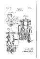
- Figure l of the drawings is a top plan view of a carburetor embodying my present invention.
- Figure 2 is a vertical sectional view of said carburetor
- Figure 3 is a vertical sectional view, taken on the line 33 of Figure 2.
- A designates the main passageway of the carburetor whose upper end communicates with the intake pipe of the engine on which the carburetor is used
- B designates an air cham- 1929.
- C designates a throttle valve arranged at the upper end of the main passageway
- D designates the fuel illustrated as a fuel nozzle which is arranged vertically so as to discharge upwardly towards the main passageway A
- E designates the float chamber of the carburetor.
- the carburetor herein illustrated is provided 59 with a plurality of venturis or suction amplifiers F, F and 1 for producing different stages of suction amplification, but said suction amplifiers or venturis form no my present invention.
- My present invention consists primarily of a carburetor equipped with a pump or similar device, arranged to operate in conjunction or in unison with the throttle Valve, and de part of signed so that when said throttle valve is 70 moved suddenly towards its open position, said pump will force a stream of air under pressure through an orifice so as to produce in effect an in'ector which causes an aerated t r accelerating charge to be supplied under pressure for a prolonged period to the main passageway of th carburetor.
- the particular type or kind of pump with which the carburetor is equipped is immaterial, and
- said pump can be operated in any preferred manner, or by any suitable means, so long as it performs the function for which it is designed, when the throttle valve is moved towards its open position.
- said pump is operatively connected with the throttle valve shaft 1 in such a way that a sudden movement of said shaft in a direction to open the throttle valve when the motor is in operation, causes air to be compressed and forced thr -n an air duct 2 which leads to an air o ifice 3 that discharges upwardly into the Iuel passageway of the nozzle D.
- the pump herein shown comprises a cylinder G arranged in an upright position at one side of the bony of the carburetor, a.
- the piston H of the pump is connected by a universal joint to the upper end of a stationary or rigid standard I, and said piston is provided'with an air port 7 that registers with an air duct '7 in the standard I, the lower end of said air duct 7* communicating with the air duct 2, previously referred to, that leads to the orifice 3 beneath'the fuel nozzle] As.
- the uni- V versal joint above mentioned is formed by a ballS on the upper end of the standard I, that is seated loosely in a socket 9' formed in the underside of the piston H, said ball being held in said socket by a removable retaining plate 10in the piston which is provided with air passageways 11 so as to permit air to flow "freely into the socket 7, and thence pass either into the air duct? in the standard I, or into the cylinder G through the port 7 in the piston.
- the air orifice 3 which, in effect, constitutes the dlscharge openlng of the pump,1s spaced away from the lower end of the fuel passage- 1 way of the nozzle D, so that the jet of air which discharges upwardly through said orifice will exert a siphoningaction on an an-c nular fuel passageway. 12 that surrounds the orifice 3, and to which fuel is supplied from ducts 7 a and 2 to the orifice 3 beneath the fuel I nozzle D.
- a pump of the construction above described can be used invarious ways to-produce pressure that is utilized to supply an acceleratingc charge to the carburetor, and accordingly, I wish it to be understood that my invention is not limited to a carburetor comprislng parts of the particular kind and ar- 1 rangement herein described and illustrated.
- a carburetor providedwith a main passageway, a throttle valve for said passageway, a pump arranged at one side of the body of the carburetor and provided with a reciprocating cylinder, a connection between said cylinder and the throttle valve shaft, a piston in said cylinder, a stationary support on which said piston is rockably mounted, an air orifice arranged so as to discharge towards the main passageway of the carbureto'r, a fuel passageway arranged adjacent said air orifice, and an air passageway through which air under pressure is dis charged. fromsaid pump cylinder to said orifice when the throttle valve is moved towards its open position.
- a carburetor provided with a main passageway, a throttle valve for said passageway, an injector for delivering an accelerating charge of fuel and air to'said main passagewa-y, and apump at one side of the body of the carburetor for causing said injector to act, consisting of a reciprocating cylinder operatively connected withthe throttle valve shaft, a piston in said-cylinder provided with an air port, a stationary support to which said piston is connected by a ball and socket joint, and an air duct in said support registering with the port in the piston and leading to said air orifice.
- V a reciprocating cylinder operatively connected withthe throttle valve shaft
- a piston in said-cylinder provided with an air port
- a stationary support to which said piston is connected by a ball and socket joint and an air duct in said support registering with the port in the piston and leading to said air orifice.
- a carburetor provided with a main passageway, a throttle valve for said passageway, a pump for producing pressure that is utilized to supply an acceleratingcharge to said main passageway, said pump comprising 7 a reciprocating cylinder operatively connected with the throttle valve, apistonin; said cylinder, and a support on which said piston is rockably mount-ed provided with an air passageway that registers with an air port, in
Landscapes
- Engineering & Computer Science (AREA)
- Chemical & Material Sciences (AREA)
- Combustion & Propulsion (AREA)
- Mechanical Engineering (AREA)
- General Engineering & Computer Science (AREA)
- Control Of The Air-Fuel Ratio Of Carburetors (AREA)
Description
Patented May 3, 1932 ilhil" i 'FICE WILLIAM C. CARTER, O13 FLINT, MICHIGAN CARIBURETOR Application filed. April 29,
which is of such construction that when the throttle valve is moved suddenly towards its open position, a stream of air under pressure will be forced through an orifice arranged in such relationship with the fuel nozzle or fuel supplying element of the carburetor, that the jet of air issuing from said orifice will exert a siphoning action on'a supply of liquid fuel surrounding said orifice, and thus cause an accelerating charge consisting of air mixed'with a supply of liquid fuel of considerable volume, to be carried upwardly through the nozzle.
And still another object is to provide a carburetor that is equipped with a pump of novel construction, which operates in conjunction with the throttle valve to produce pressure which is utilized to supply an accelerating charge to the carburetor.
Figure l of the drawings is a top plan view of a carburetor embodying my present invention.
Figure 2 is a vertical sectional view of said carburetor; and
Figure 3 is a vertical sectional view, taken on the line 33 of Figure 2.
I have herein illustrated my present invention embodied in a carburetor of the design shown in my pending application for patent Serial No. 359,100, filed April 29, 1929, which matured to Patent No. 1,809,507, granted June 9, 1931, but I wish it to be understood that my invention is applicable to various other types and kinds of carburetors.
In the accompanying drawings which illustrate the preferred form of my invention. A designates the main passageway of the carburetor whose upper end communicates with the intake pipe of the engine on which the carburetor is used, B designates an air cham- 1929. Serial No. 359,096.
her which communicates with the lower end of said main passageway, C designates a throttle valve arranged at the upper end of the main passageway, D designates the fuel illustrated as a fuel nozzle which is arranged vertically so as to discharge upwardly towards the main passageway A, and E designates the float chamber of the carburetor.
supplyiu element of the carburetor, herein The carburetor herein illustrated is provided 59 with a plurality of venturis or suction amplifiers F, F and 1 for producing different stages of suction amplification, but said suction amplifiers or venturis form no my present invention.
My present invention consists primarily of a carburetor equipped with a pump or similar device, arranged to operate in conjunction or in unison with the throttle Valve, and de part of signed so that when said throttle valve is 70 moved suddenly towards its open position, said pump will force a stream of air under pressure through an orifice so as to produce in effect an in'ector which causes an aerated t r accelerating charge to be supplied under pressure for a prolonged period to the main passageway of th carburetor. The particular type or kind of pump with which the carburetor is equipped is immaterial, and
said pump can be operated in any preferred manner, or by any suitable means, so long as it performs the function for which it is designed, when the throttle valve is moved towards its open position. Preferably, said pump is operatively connected with the throttle valve shaft 1 in such a way that a sudden movement of said shaft in a direction to open the throttle valve when the motor is in operation, causes air to be compressed and forced thr -n an air duct 2 which leads to an air o ifice 3 that discharges upwardly into the Iuel passageway of the nozzle D. The pump herein shown comprises a cylinder G arranged in an upright position at one side of the bony of the carburetor, a. piston H in said cylinder, a rigid arm l attached to the upper c of the cylinder G and projecting upwardly from same, and a lever 5 on the throttle v'alve shaft 1 attached by a pivot pin 6 to the upper end of the arm 4. The piston H of the pump is connected by a universal joint to the upper end of a stationary or rigid standard I, and said piston is provided'with an air port 7 that registers with an air duct '7 in the standard I, the lower end of said air duct 7* communicating with the air duct 2, previously referred to, that leads to the orifice 3 beneath'the fuel nozzle] As. shown in Figure 3, the uni- V versal joint above mentioned is formed by a ballS on the upper end of the standard I, that is seated loosely in a socket 9' formed in the underside of the piston H, said ball being held in said socket by a removable retaining plate 10in the piston which is provided with air passageways 11 so as to permit air to flow "freely into the socket 7, and thence pass either into the air duct? in the standard I, or into the cylinder G through the port 7 in the piston.
' The air orifice 3, which, in effect, constitutes the dlscharge openlng of the pump,1s spaced away from the lower end of the fuel passage- 1 way of the nozzle D, so that the jet of air which discharges upwardly through said orifice will exert a siphoningaction on an an-c nular fuel passageway. 12 that surrounds the orifice 3, and to which fuel is supplied from ducts 7 a and 2 to the orifice 3 beneath the fuel I nozzle D. The jet of air, in escaping upwardly through the orifice 3, produces a siphoning action on thefuel in the fuel passageway 12, that causes a relatively great quantity of fuel to be sucked out of said passageway, mixed with the air emerging from the v orifice 3, and then carrled upwardly throughthe nozzle to form an accelerating charge of liquid fuel and air which passes into the main assageway A of the carburetor., Due to t e fact that this accelerating charge continues vto flow upwardly through the nozzle D during the entire downward stroke of the cylinder G of the pump, said charge will be supplied for a sufiiciently long period to the main passageway of the carburetor to accelerate the speed of the engine on which the carburetor is used,
A pump of the construction above describedcan be used invarious ways to-produce pressure that is utilized to supply an acceleratingc charge to the carburetor, and accordingly, I wish it to be understood that my invention is not limited to a carburetor comprislng parts of the particular kind and ar- 1 rangement herein described and illustrated.
Having thus described my invention, what I claim as new and desire to secure by Letters Patent is:
1. A carburetor providedwith a main passageway, a throttle valve for said passageway, a pump arranged at one side of the body of the carburetor and provided with a reciprocating cylinder, a connection between said cylinder and the throttle valve shaft, a piston in said cylinder, a stationary support on which said piston is rockably mounted, an air orifice arranged so as to discharge towards the main passageway of the carbureto'r, a fuel passageway arranged adjacent said air orifice, and an air passageway through which air under pressure is dis charged. fromsaid pump cylinder to said orifice when the throttle valve is moved towards its open position.
2. A carburetor provided with a main passageway, a throttle valve for said passageway, an injector for delivering an accelerating charge of fuel and air to'said main passagewa-y, and apump at one side of the body of the carburetor for causing said injector to act, consisting of a reciprocating cylinder operatively connected withthe throttle valve shaft, a piston in said-cylinder provided with an air port, a stationary support to which said piston is connected by a ball and socket joint, and an air duct in said support registering with the port in the piston and leading to said air orifice. V a
3. A carburetor provided with a main passageway, a throttle valve for said passageway, a pump for producing pressure that is utilized to supply an acceleratingcharge to said main passageway, said pump comprising 7 a reciprocating cylinder operatively connected with the throttle valve, apistonin; said cylinder, and a support on which said piston is rockably mount-ed provided with an air passageway that registers with an air port, in
said piston. 1 j a WILLIAM G. CARTER.
Priority Applications (1)
| Application Number | Priority Date | Filing Date | Title |
|---|---|---|---|
| US359096A US1856464A (en) | 1929-04-29 | 1929-04-29 | Carburetor |
Applications Claiming Priority (1)
| Application Number | Priority Date | Filing Date | Title |
|---|---|---|---|
| US359096A US1856464A (en) | 1929-04-29 | 1929-04-29 | Carburetor |
Publications (1)
| Publication Number | Publication Date |
|---|---|
| US1856464A true US1856464A (en) | 1932-05-03 |
Family
ID=23412283
Family Applications (1)
| Application Number | Title | Priority Date | Filing Date |
|---|---|---|---|
| US359096A Expired - Lifetime US1856464A (en) | 1929-04-29 | 1929-04-29 | Carburetor |
Country Status (1)
| Country | Link |
|---|---|
| US (1) | US1856464A (en) |
-
1929
- 1929-04-29 US US359096A patent/US1856464A/en not_active Expired - Lifetime
Similar Documents
| Publication | Publication Date | Title |
|---|---|---|
| US3404872A (en) | Charge forming apparatus | |
| US1856464A (en) | Carburetor | |
| US2261490A (en) | Carburetor | |
| US2246825A (en) | Carburetor | |
| US2399637A (en) | Carburetor | |
| US1263570A (en) | Carbureter. | |
| US1979918A (en) | Carburetor | |
| US2323984A (en) | Carburetor | |
| US3233878A (en) | Charge forming apparatus | |
| US2207456A (en) | Carburetor structure | |
| US3679186A (en) | Single fuel system carburetor having improved metering stability | |
| US1977661A (en) | Carburetor | |
| US1781087A (en) | Carburetor | |
| US1384429A (en) | Carbureter | |
| US1414035A (en) | Carburetor | |
| US1356661A (en) | Carbureter | |
| US2224152A (en) | Carburetor | |
| US1927426A (en) | Carburetor | |
| US1809507A (en) | Carburetor | |
| US2057552A (en) | Carburetor | |
| US1718652A (en) | Carburetor | |
| US1748149A (en) | Carburetor | |
| US1395950A (en) | Vacuum-carbureter | |
| US1825381A (en) | Multiple carburetor charge forming device | |
| US1855182A (en) | Carburetor |