US1856448A - Electric switch - Google Patents
Electric switch Download PDFInfo
- Publication number
- US1856448A US1856448A US313150A US31315028A US1856448A US 1856448 A US1856448 A US 1856448A US 313150 A US313150 A US 313150A US 31315028 A US31315028 A US 31315028A US 1856448 A US1856448 A US 1856448A
- Authority
- US
- United States
- Prior art keywords
- contact
- contacts
- carriage
- members
- base
- Prior art date
- Legal status (The legal status is an assumption and is not a legal conclusion. Google has not performed a legal analysis and makes no representation as to the accuracy of the status listed.)
- Expired - Lifetime
Links
- 230000006835 compression Effects 0.000 description 2
- 238000007906 compression Methods 0.000 description 2
- 230000001143 conditioned effect Effects 0.000 description 2
- 230000000694 effects Effects 0.000 description 2
- 238000004519 manufacturing process Methods 0.000 description 2
- 238000000926 separation method Methods 0.000 description 2
- RYGMFSIKBFXOCR-UHFFFAOYSA-N Copper Chemical compound [Cu] RYGMFSIKBFXOCR-UHFFFAOYSA-N 0.000 description 1
- 230000000295 complement effect Effects 0.000 description 1
- 239000004020 conductor Substances 0.000 description 1
- 229910052802 copper Inorganic materials 0.000 description 1
- 239000010949 copper Substances 0.000 description 1
- 210000005069 ears Anatomy 0.000 description 1
- 230000005611 electricity Effects 0.000 description 1
- 239000012634 fragment Substances 0.000 description 1
- 230000000977 initiatory effect Effects 0.000 description 1
- 238000007689 inspection Methods 0.000 description 1
- 239000002184 metal Substances 0.000 description 1
- 229910052751 metal Inorganic materials 0.000 description 1
- 239000011435 rock Substances 0.000 description 1
Images

Classifications
-
- H—ELECTRICITY
- H01—ELECTRIC ELEMENTS
- H01H—ELECTRIC SWITCHES; RELAYS; SELECTORS; EMERGENCY PROTECTIVE DEVICES
- H01H21/00—Switches operated by an operating part in the form of a pivotable member acted upon directly by a solid body, e.g. by a hand
- H01H21/02—Details
Definitions
- This invention relates to an electric switch mechanism and has for an obj ect a provision of a device wherein there is effected a saving of space due to a reduction of space necessary for operation of the moving parts switch.
- Another object is to provide a device wherein'thev space which is usually filled up with insulating bases and the like, is utilized for the contacts and fuses.
- Another object is to provide a structure of this kind wherein the parts indicating contacts are visible and accessible for inspection y when thek cover is removed.
- Another object is to provide a switch structure adapted for quick make and break of the contact and one which is inexpensive of manufacture and very efficient in operation.
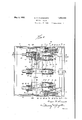
- Fig. 1 is a cross-sectional elevation of a switch box of the invention.
- Fig. 2 is a cross-sectional view taken on line 2--2 of Fig. 1.
- Fig. 3 is a view taken on line 3-3 of Fig. 2.
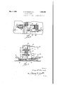
- Fig. 4 is a detail showing in plan a fragment, in modiied form, of the invention.
- Fig. 5 is a view taken on line 5-5 of Fig. 4.
- the switch comprises a sheet metal box having a bottom wall 8, side. walls 9 and a two part detachable cover member 10. Secured to a transverse metallic bridge 11, the uprights or supports of one pair of opposed walls 9.
- an insulating strip 13 on the under-face of which are secured straps 14 of electricity conducting material, such as copper, the ends of which are turned downwardly at 15 to provide switch contacts disposed along one edge of theV member 13.
- the opposite ends 16 of the straps 14 are turned downk in substantial parallelism and have electrically attached thereto, fuse clips ⁇ 17.
- a thin sheet of insulating material18 covers the lower faces of the straps 14. It will be noted in Fig. 2 that the' outermost of the straps 14 may diverge for Serial No. 313,150.
- An intermediate insulating block 23 is secured to the bottom 8 of the box and has a contact member 24 secured thereto with an upstanding portion aligned with the intermediate contact portion 15.
- These contacts 21 and 24 are secured in position by suitable screws 25 which also serve to connect line terminals 26 in electrical contact therewith.
- On each of the upstanding members 27 is a fuse clip member 17, paired with a similar clip member above it for receiving a cartridge type fuse and holding it perpendicular to the base 8 of the box.
- the load terminals 29 Suitably secured upon the members 28 are the load terminals 29.
- a pair of angle plates 3() comprising a central mounting 31 for a pivot 32 and stops 33 and 34 on opposite sides of the portion 31. These parts are substantially uniform, wherefore only one need be described.
- the pair of aligned pivots 32 have their outer ends riveted in the side walls 9 of the box.
- a pair of pirated levers 35 are mounted one each upon the opposed pivots 32 and have their ends turned at right angles thereto and perforated for slidably receiving'spring retailiing rods 37.
- the arms 35 also have securely mounted thereon, odset arms 38 which receive pivots 39 for operatively connecting members 35 with a reciprocating actuator yoke 40.
- the yoke 40 may comprise a strip to which are secured members 41, the ends 42 ofwhich are turned and perforated to complete the sliding pivotal connection with the arm 38.
- the members ustfdescribed are operatively connected with a pair of reciprocating plates 43, which are slotted as at 44 and are limited inv their movement along the side Walls by aV lug 45 extending into the slot.
- An elongated aperture'46 is formed in the oppo site end ot' the plates 43-and similarly guides and limits the opposite ends of the plates on lugs 47.
- Y f' A transverse strip 48,'which maybe channel shaped to impart rigidity to it, has its ends 490 turned at right angles and secured to the plates 43.
- Thesliding plates 43 and the transverse members 48 provide a recproeatingV carriage which has movement parallel to the bottom oribase 8 of thebox.
- the member 48 however, extends perpendicular to the b'aseand carries a bridge contact 49 for AeachV pair of terminal members 22-15
- the bridge .contact members 49 are capable of limited yielding movement, being slidably mounted on pins-5,0 secured in an insulating bar 5l mounted on the member 48.
- Springs 52 surround the pins 50 and provide a yieldving abutment yfor the bridge bars 49.
- suitablemeans such as rivetheads 53, preclude separation of a bridge contact 49 from the pms 50.
- any suitable means may be employed for reciprocating the carriage structure, however, as shown herein','the manual actuation of. the Acarriage serves to build up force against spring tension which is auto1natically released for providing an automatic quick make and break between the contacts.
- the arm 35 has a Y bent-over end portionV 36, slotted to receive a relative reciprocating member 37.
- the enlarged end 55 of rod 37 is perforated with a sort of key-hole opening which is best seen in Fig; 3 so that a key 55, which forms a part of a clip 57, may berpivotally connected with the arm 37.
- the clip 57 has a dat leaf-like portion 58 disposed on each side of the plate 43 and these leaves are connected by the narrow neck 57 which may move in a vertical slot 59 in plate 43.
- lThus bypushing on 'the bar 40 the arms 35 are turned about their fixed axes on the pivots 32 andin doing so the projecting ends 36 compress springs 54'.
- the force Aof the springs now presses upon the keys 56 which rocks the clip structure 57 on the plates 43 and allows the l ⁇ force or" the spring to quickly thrust the carriage structure forwardly to form a Contact betweenthe bridge contacts 49 and the contacts22-l5.
- member 40 In breaking the contact, member 40 is moved in the opposite direction, which stores up the energy in springs 54 until they arms ⁇ 35 are well past top dead center, whereuponthe force ofthev spring is released for eiTecting instantaneous breaking of the contact.
- the operator may at'- tempt to move the switch rapidly or slowly, his manual movement serves merely to store up energy inthe springs 54 and upon apredetermined relation of the parts, as explained, the carriage structure will automatically become'released tothe'movement of the springs;
- the transverse member 40 is shown with a ring 60 suitably connectedand serving to actuate the switch with 'a simple push and pullmovement.
- a crank lever at the side of the box.
- the flatV cont-act members l5 and 22 and their bridging Contact 49 maybe of a'vshapeL other than fiat, for example, the membersl and 22may be in the form oi/ shaped ⁇ jaws.
- Y i' The embodiment heretofore described, provides for the making and breaking orn a circuit through the switch in which the 4fuses are not cut oli" from the load side ofthe circuit when contact is broken with the supply or line contacts.
- lIn Figs. 4 and 5 are shown details of a structure oftheinvention which is modi-V tied to provide a double break which simultaneously disconnects the contacts on the line or supply side of the box and disconnects the fuses fromthe load terminals yof the box.
- the upper fuse clips 6l are mounted on straps 62 which have downwardly projecting con# tacts 63 beneath linsulating strips 64, kwhile the lower fuse clips 65 are mounted on upstanding projections 66 ofV a strap67, which has va depending contact 68 on the end thereing members 75 mounted on a carriage as previously described, has pins 76 extending Jfrom one side and pins 77 extending from the other'side, ⁇ for mormting bridging contacts 78 and 79, respectively, in the manner previously taught.
- the bridging contact 7 8 Upon movement of the insulating members 7 5, the bridging contact 7 8 will contact with members 7 4 and G8, While the bridging contact- 79 actuated simultaneously therewith, will complete a circuit between contacts 63 .and 71.
- the electrical circuit through the structure shown would be from line terminal 7 3, through contact 74, bridge contact 78, contact 68, strap 67 and its upstanding projections 66, to fuse clip 65, then through the fuse (not shown), to upper clip 61, through strap 62, contacts 63, bridge Contact 7 9, contact 71, member 69, to load terminal 70.
- the contact Upon reversing the carriage, the contact would be broken at two places, thus leaving the fuse clips dead from the line and disconnected from the load as well.
- the twopart cover l() has suitable flanging 80 around its edges to provide for a neat edge Y to edge Contact between the box wall 9 and the cover members.
- the member l0 connects with the bridging member l1 by means of screws 8l which are easily removed to detach the cover from the box entirely. Then the cover is attached as shown in Fig. l, the line terminals 26 are inaccessible and the hinged portion 82 of the cover may be raised to afford access to the fuses.
- the hinge connection maybe simple as disclosed in Fig. l where a pair of pert'orate ears 83 are pivotally connected with the sides of cover member l0 by means of pins 84.
- Vhat is claimed is:
- a switch box structure the combination of a cabinet having a base, a pair of spaced contact members disposed one above the other at one side of the base, a spring propelled carriage slidable parallel to the base, a bridge contact transversely mounted on one side of the carriage for effecting electrical connection between the spaced contacts and manually actuated means for initiating action oi the spring on the carriage.
- a switch structure having a base, pairs of spaced contacts, each pair arranged one contact above the other within the cabinet above the base, reciprocably mounted members for making and breaking electrical contact beelectrically connected with the remaining contacts of the said pairs, the fuse receptacles being electrically connected and disconnected from the said line terminals instantaneously as the manually operated means conditions the spring mechanism for moving the reciprocating members.
- a closable cabinet hav-- ing a base, spaced contacts disposed adjacent the top andvbottom of the cabinet in alignment perpendicular to the base, a line terminal connected to one of said contacts,com plementary fuse receptacle members connected to the other of said contacts and a spring actuated perpendicular member ⁇ Inovable. parallel to the base for connecting and disconnecting said spaced contacts.
- a cabinet comprising a base, pairs of aligned spaced contacts at one side ofthe cabinet, one of each pair at the bottom .and the other at the top of the cabinet, fuse receptacles at the other side of the cabinetand electrically connected one each to one of each pair of contacts, supply line terminals electrically connected to the remaining of said contacts and a manually conditioned spring actuated member for effecting instantaneous making and breaking of electrical connection between the pairs of contacts.
- a relatively shallow cabinet having a base, a pair of spaced contact members arranged in alignment adjacent the top and base of the cabinet, a line terminal connected toy one of lsaid contacts, a fuse receiving means connected to the other of said contacts, a bridge contact member disposed vertically of ⁇ the base and mounted for bodily reciprocation horizontally of said base, for connecting said pair of contacts, a yspring mechanism adapted to be manually conditioned for subsequently self liberated projection of the bridge Contact member toward and from said pair of spaced contacts.
- a cabinet having a base, side walls, and a cover, pairs of contacts disposed at the top and bottom of the cabinet, a carriage slidably mounted on opposed side walls for movement parallel with the base, an insulating member extending across the cabinet and movable with the carriage, bridging members mounted on said insulating member and movable thereby into and out of contact with pairs of contacts, and means comprising springs and compressing means therefor to effect rapid projection of the carriage.
- actuating mechanism forasliding carriage comprising a pair ofV support lugs, Y
- a carriage member having slots therein for receiving said lugsy and also having a transversely extending aperture therein, a pair of arms independently mounted for pivotal movement on a common liXed axis, a compression rspring having its opposite ends in abutmentwith said arms andv exerting its force in a plane parallel with said arms and means on one of saidarms yfor operatively connecting it in the transverse aperture in the carriage.
Landscapes
- Fuses (AREA)
Description
May 3, 1932. G.B.WADSWORTH 1,856,448
ELECTRIC SWITCH Filed oct. 17, v1922s ,3 sheets-sheet 2 May 3, 1.932. G. B. wADsWoRTH 1,856,448
ELECTRIC SWITCH Filed Oct. 17, 1928 3 Sheets-Sheet 3 f Patented May 3, 1932 narran s'rAres PATENT OFFICE GEORGE B. WADSWORTH, CE? COVINGTON, KENT CKY, ASSIGNOR TO THE XVADSWORTH i ELECTRIC MANUFACTURING COMPANY, OF COVINGTON, KENTUCKY, A. CORPORA- 'rIoN or KENTUCKY ELECTRIC SWITCH Application led October 17, 19,28.
This invention relates to an electric switch mechanism and has for an obj ect a provision of a device wherein there is effected a saving of space due to a reduction of space necessary for operation of the moving parts switch.
Another object is to provide a device wherein'thev space which is usually filled up with insulating bases and the like, is utilized for the contacts and fuses.
Another object is to provide a structure of this kind wherein the parts indicating contacts are visible and accessible for inspection y when thek cover is removed.
Another object is to provide a switch structure adapted for quick make and break of the contact and one which is inexpensive of manufacture and very efficient in operation. These and other objects are attained by the means described herein and disclosed in the accompanying drawing in which:
Fig. 1 is a cross-sectional elevation of a switch box of the invention.
Fig. 2 is a cross-sectional view taken on line 2--2 of Fig. 1.
Fig. 3 is a view taken on line 3-3 of Fig. 2.
Fig. 4 is a detail showing in plan a fragment, in modiied form, of the invention.
Fig. 5 is a view taken on line 5-5 of Fig. 4.
ln the embodiment shown herein the switch comprises a sheet metal box having a bottom wall 8, side. walls 9 and a two part detachable cover member 10. Secured to a transverse metallic bridge 11, the uprights or supports of one pair of opposed walls 9.
12 of which are secured to the interior faces Secured beneath the lower face of the metallic bridge 11 is an insulating strip 13 on the under-face of which are secured straps 14 of electricity conducting material, such as copper, the ends of which are turned downwardly at 15 to provide switch contacts disposed along one edge of theV member 13. The opposite ends 16 of the straps 14 are turned downk in substantial parallelism and have electrically attached thereto, fuse clips`17. A thin sheet of insulating material18 covers the lower faces of the straps 14. It will be noted in Fig. 2 that the' outermost of the straps 14 may diverge for Serial No. 313,150.
the purpose of securing ample separation between the contacts 15.
On the interior face of the bottom 8 are secured insulating blocks 19 with offset ends 20 upon which are secured contacts 21 having upstanding contact faces 22, which are in alignment with the endmost of the depending members 15 above. An intermediate insulating block 23 is secured to the bottom 8 of the box and has a contact member 24 secured thereto with an upstanding portion aligned with the intermediate contact portion 15. These contacts 21 and 24 are secured in position by suitable screws 25 which also serve to connect line terminals 26 in electrical contact therewith. On the blocks 19 and 23, opposite the terminals 26, are secured upstanding L shaped electrical members 27 secured through arms 28 to the blocks and having their upstanding portions 27 aligned with the depending member 1G above. On each of the upstanding members 27 is a fuse clip member 17, paired with a similar clip member above it for receiving a cartridge type fuse and holding it perpendicular to the base 8 of the box. Suitably secured upon the members 28 are the load terminals 29.
At opposite ends of the row of load terminals 29 are secured interiorly of the box, a pair of angle plates 3() comprising a central mounting 31 for a pivot 32 and stops 33 and 34 on opposite sides of the portion 31. These parts are substantially uniform, wherefore only one need be described. The pair of aligned pivots 32 have their outer ends riveted in the side walls 9 of the box. A pair of pirated levers 35 are mounted one each upon the opposed pivots 32 and have their ends turned at right angles thereto and perforated for slidably receiving'spring retailiing rods 37. The arms 35 also have securely mounted thereon, odset arms 38 which receive pivots 39 for operatively connecting members 35 with a reciprocating actuator yoke 40. The yoke 40 may comprise a strip to which are secured members 41, the ends 42 ofwhich are turned and perforated to complete the sliding pivotal connection with the arm 38.
The members ustfdescribed are operatively connected with a pair of reciprocating plates 43, which are slotted as at 44 and are limited inv their movement along the side Walls by aV lug 45 extending into the slot. An elongated aperture'46 is formed in the oppo site end ot' the plates 43-and similarly guides and limits the opposite ends of the plates on lugs 47. Y f' A transverse strip 48,'which maybe channel shaped to impart rigidity to it, has its ends 490 turned at right angles and secured to the plates 43. Thesliding plates 43 and the transverse members 48 provide a recproeatingV carriage which has movement parallel to the bottom oribase 8 of thebox. The member 48 however, extends perpendicular to the b'aseand carries a bridge contact 49 for AeachV pair of terminal members 22-15 The bridge .contact members 49 are capable of limited yielding movement, being slidably mounted on pins-5,0 secured in an insulating bar 5l mounted on the member 48. Springs 52 surround the pins 50 and provide a yieldving abutment yfor the bridge bars 49. Any
suitablemeans, such as rivetheads 53, preclude separation of a bridge contact 49 from the pms 50.
' Y l,Thus when the carriage'bearing the bridge contacts 49 is vmoved from the position shown in Fig. 3,-.totheposition shown in Fig. l', the top of the Contact l49 strikes the face of depending contact 15 while the bottom portion of the face of contact 49 strikes the upf standing ace`22 of contact 2l, thus completing an electric circuit from the line terminal 26 through contact 2,1,.bridge contact 49,
dependingcontact l5', strap 14, from upper fusev clip 17, through a' fuse (not shown), through lower face clip V17, Contact 23 and loadterminal 29.
vThe springs 52 previously described, rserve to cushion the impact of'bridge Contact 49 againstthe contacts v25E-15.
Any suitable means may be employed for reciprocating the carriage structure, however, as shown herein','the manual actuation of. the Acarriage serves to build up force against spring tension which is auto1natically released for providing an automatic quick make and break between the contacts.
'As previously explained, the arm 35 has a Y bent-over end portionV 36, slotted to receive a relative reciprocating member 37. A compression spring 54jencircles the rod 37 which is enlarged ask at 55 to provide an abutment for one end of spring 54, the other end of whichabuts the face ofV the member 36 on arm 35. The enlarged end 55 of rod 37 is perforated with a sort of key-hole opening which is best seen in Fig; 3 so that a key 55, which forms a part of a clip 57, may berpivotally connected with the arm 37. The clip 57 has a dat leaf-like portion 58 disposed on each side of the plate 43 and these leaves are connected by the narrow neck 57 which may move in a vertical slot 59 in plate 43. lThus, bypushing on 'the bar 40 the arms 35 are turned about their fixed axes on the pivots 32 andin doing so the projecting ends 36 compress springs 54'. When the arms 35V have been moved oit-center the force Aof the springs now presses upon the keys 56 which rocks the clip structure 57 on the plates 43 and allows the l `force or" the spring to quickly thrust the carriage structure forwardly to form a Contact betweenthe bridge contacts 49 and the contacts22-l5.
In breaking the contact, member 40 is moved in the opposite direction, which stores up the energy in springs 54 until they arms`35 are well past top dead center, whereuponthe force ofthev spring is released for eiTecting instantaneous breaking of the contact. Thus, regardless ofwhetherthe operator may at'- tempt to move the switch rapidly or slowly, his manual movement serves merely to store up energy inthe springs 54 and upon apredetermined relation of the parts, as explained, the carriage structure will automatically become'released tothe'movement of the springs;
ln the present embodimentl the transverse member 40 is shown with a ring 60 suitably connectedand serving to actuate the switch with 'a simple push and pullmovement.` It will be readily appreciated thatL the same movement however, may be attained through other means', as for example, a crank lever at the side of the box. ,y y
y It will be further understood that the flatV cont-act members l5 and 22 and their bridging Contact 49, maybe of a'vshapeL other than fiat, for example, the membersl and 22may be in the form oi/ shaped `jaws. Y i' The embodiment heretofore described, provides for the making and breaking orn a circuit through the switch in which the 4fuses are not cut oli" from the load side ofthe circuit when contact is broken with the supply or line contacts. lIn Figs. 4 and 5 are shown details of a structure oftheinvention which is modi-V tied to provide a double break which simultaneously disconnects the contacts on the line or supply side of the box and disconnects the fuses fromthe load terminals yof the box. In order to provide torthe double break between the line, fuses andV load terminals, the upper fuse clips 6l are mounted on straps 62 which have downwardly projecting con# tacts 63 beneath linsulating strips 64, kwhile the lower fuse clips 65 are mounted on upstanding projections 66 ofV a strap67, which has va depending contact 68 on the end thereing members 75 mounted on a carriage as previously described, has pins 76 extending Jfrom one side and pins 77 extending from the other'side, `for mormting bridging contacts 78 and 79, respectively, in the manner previously taught. Upon movement of the insulating members 7 5, the bridging contact 7 8 will contact with members 7 4 and G8, While the bridging contact- 79 actuated simultaneously therewith, will complete a circuit between contacts 63 .and 71. Thus, the electrical circuit through the structure shown would be from line terminal 7 3, through contact 74, bridge contact 78, contact 68, strap 67 and its upstanding projections 66, to fuse clip 65, then through the fuse (not shown), to upper clip 61, through strap 62, contacts 63, bridge Contact 7 9, contact 71, member 69, to load terminal 70. Upon reversing the carriage, the contact would be broken at two places, thus leaving the fuse clips dead from the line and disconnected from the load as well.
The twopart cover l() has suitable flanging 80 around its edges to provide for a neat edge Y to edge Contact between the box wall 9 and the cover members. The member l0 connects with the bridging member l1 by means of screws 8l which are easily removed to detach the cover from the box entirely. Then the cover is attached as shown in Fig. l, the line terminals 26 are inaccessible and the hinged portion 82 of the cover may be raised to afford access to the fuses. The hinge connection maybe simple as disclosed in Fig. l where a pair of pert'orate ears 83 are pivotally connected with the sides of cover member l0 by means of pins 84.
It will be understood that the 'fixed and movable contacts, herein described and shown in the drawings as perpendicular to the base or bottom wall of the box, need not necessarily be so disposed. It is contemplated within the scope of this invention, that all or certain sets of the contact members may be inclined at other angles when desirable to accommodate the structure herein to changes in design.
Vhat is claimed is:
l. In a switch box structure the combination of a cabinet having a base, a pair of spaced contact members disposed one above the other at one side of the base, a spring propelled carriage slidable parallel to the base, a bridge contact transversely mounted on one side of the carriage for effecting electrical connection between the spaced contacts and manually actuated means for initiating action oi the spring on the carriage.
2. In a switch structure the combination of a cabinet having a base, pairs of spaced contacts, each pair arranged one contact above the other within the cabinet above the base, reciprocably mounted members for making and breaking electrical contact beelectrically connected with the remaining contacts of the said pairs, the fuse receptacles being electrically connected and disconnected from the said line terminals instantaneously as the manually operated means conditions the spring mechanism for moving the reciprocating members.
3. In combination a closable cabinet hav-- ing a base, spaced contacts disposed adjacent the top andvbottom of the cabinet in alignment perpendicular to the base, a line terminal connected to one of said contacts,com plementary fuse receptacle members connected to the other of said contacts and a spring actuated perpendicular member `Inovable. parallel to the base for connecting and disconnecting said spaced contacts.
.4. In a device ofthe class described the combination of a cabinet comprising a base, pairs of aligned spaced contacts at one side ofthe cabinet, one of each pair at the bottom .and the other at the top of the cabinet, fuse receptacles at the other side of the cabinetand electrically connected one each to one of each pair of contacts, supply line terminals electrically connected to the remaining of said contacts and a manually conditioned spring actuated member for effecting instantaneous making and breaking of electrical connection between the pairs of contacts. V
5. In a device of the class described the combination of a relatively shallow cabinet having a base, a pair of spaced contact members arranged in alignment adjacent the top and base of the cabinet, a line terminal connected toy one of lsaid contacts, a fuse receiving means connected to the other of said contacts, a bridge contact member disposed vertically of` the base and mounted for bodily reciprocation horizontally of said base, for connecting said pair of contacts, a yspring mechanism adapted to be manually conditioned for subsequently self liberated projection of the bridge Contact member toward and from said pair of spaced contacts.
f 6. In combination, a cabinet having a base, side walls, and a cover, pairs of contacts disposed at the top and bottom of the cabinet, a carriage slidably mounted on opposed side walls for movement parallel with the base, an insulating member extending across the cabinet and movable with the carriage, bridging members mounted on said insulating member and movable thereby into and out of contact with pairs of contacts, and means comprising springs and compressing means therefor to effect rapid projection of the carriage.
ion
' trical connection between said V'a transverse member spacedl from the base, contact members extending from the base and said 'transverse member, a carriage recipro- 7. n actuating mechanism forasliding carriage, comprising a pair ofV support lugs, Y
a carriage member having slots therein for receiving said lugsy and also having a transversely extending aperture therein, a pair of arms independently mounted for pivotal movement on a common liXed axis, a compression rspring having its opposite ends in abutmentwith said arms andv exerting its force in a plane parallel with said arms and means on one of saidarms yfor operatively connecting it in the transverse aperture in the carriage. Y
8. In combination a line terminal, a load terminal, contacts connected with each terminal, a pair of spaced fuse clips, a connector 'extending from one clip and terminating 1n a contact paired'with the line termnalicontact, a connector-extending from the other clip andterminatingin a Contact paired with Y the load terminal Contact and a pairof movable members for making and breaking elecy pairsof contacts. Y 1 i Y "9, In combination acabinet havinga base,
cable between the basek and transversev memfber, electrical bridgemembers on the 1ar-l riage and each arranged to have one end abut a Contact on the transverse-member and the Y other end abut a Contact onthe base when l the carriageis moved to one limit of reciprocation and to break abutting contactl when v Vthev carriage is moved away from saidlimit of reciprocation and means to initiateuncontrolled quick reciprocation of the carriage.
10. InY combination arpair of oppositely extending contacts spaced at a distance one from the other, a sidewisely movable carriage ieciprocable in a plane'between the contacts,
bridge contact bars mounted transversely of scribed my *fos the 'carriage for connecting said cont-acts and precluding movementof thecarriage into the space betweenV contacts andx means connected f to opposite ends of the carriage to effect rapid movement of the carriage whereby the opposite ends of each Contact bar are Carried into and from abutment with a given pair of the contacts.V
In testimony whereof, I have hereunto sub- 1928. Y v GEORGE WADSWORTI-I.
name this lst'pday 'of October, v
Priority Applications (1)
| Application Number | Priority Date | Filing Date | Title |
|---|---|---|---|
| US313150A US1856448A (en) | 1928-10-17 | 1928-10-17 | Electric switch |
Applications Claiming Priority (1)
| Application Number | Priority Date | Filing Date | Title |
|---|---|---|---|
| US313150A US1856448A (en) | 1928-10-17 | 1928-10-17 | Electric switch |
Publications (1)
| Publication Number | Publication Date |
|---|---|
| US1856448A true US1856448A (en) | 1932-05-03 |
Family
ID=23214581
Family Applications (1)
| Application Number | Title | Priority Date | Filing Date |
|---|---|---|---|
| US313150A Expired - Lifetime US1856448A (en) | 1928-10-17 | 1928-10-17 | Electric switch |
Country Status (1)
| Country | Link |
|---|---|
| US (1) | US1856448A (en) |
Cited By (1)
| Publication number | Priority date | Publication date | Assignee | Title |
|---|---|---|---|---|
| US2574290A (en) * | 1947-01-16 | 1951-11-06 | Gen Electric | Multiple unit switch with single actuator |
-
1928
- 1928-10-17 US US313150A patent/US1856448A/en not_active Expired - Lifetime
Cited By (1)
| Publication number | Priority date | Publication date | Assignee | Title |
|---|---|---|---|---|
| US2574290A (en) * | 1947-01-16 | 1951-11-06 | Gen Electric | Multiple unit switch with single actuator |
Similar Documents
| Publication | Publication Date | Title |
|---|---|---|
| US1856448A (en) | Electric switch | |
| US2005441A (en) | Electrical connecter | |
| US3320392A (en) | Electric control device with improved contact structure | |
| US2295577A (en) | Electric switch | |
| US2154247A (en) | Electric lamp socket | |
| US2842640A (en) | Cam-actuated, quick break electric switch | |
| US1176202A (en) | Circuit-controlling apparatus. | |
| US1783731A (en) | Inclosed switch | |
| US2186640A (en) | Safety switch mechanism | |
| US1741222A (en) | Fuse puller | |
| US1240314A (en) | Oil-switch. | |
| US1421589A (en) | Electric press iron | |
| US1853752A (en) | Quick acting switch | |
| US1749200A (en) | Electric switch | |
| US1649694A (en) | Electric switch | |
| US1625149A (en) | Electric switch | |
| US1687199A (en) | Electbic switch | |
| US2268943A (en) | Fused switch box | |
| US2202170A (en) | Switch lock construction | |
| US1744200A (en) | Circuit breaker | |
| GB774208A (en) | Combined electrical switch and socket outlet | |
| US2635151A (en) | Electric switch or switch-fuse unit | |
| US1876840A (en) | Lamp changing mechanism for beacons | |
| US1866333A (en) | Inclosed electric switch | |
| US1530353A (en) | Heating stand for electric irons |