US1856436A - Bank, turn, and climb indicator for aircraft - Google Patents
Bank, turn, and climb indicator for aircraft Download PDFInfo
- Publication number
- US1856436A US1856436A US279488A US27948828A US1856436A US 1856436 A US1856436 A US 1856436A US 279488 A US279488 A US 279488A US 27948828 A US27948828 A US 27948828A US 1856436 A US1856436 A US 1856436A
- Authority
- US
- United States
- Prior art keywords
- turn
- aircraft
- indicator
- bank
- gyroscope
- Prior art date
- Legal status (The legal status is an assumption and is not a legal conclusion. Google has not performed a legal analysis and makes no representation as to the accuracy of the status listed.)
- Expired - Lifetime
Links
- 238000010276 construction Methods 0.000 description 4
- 230000009194 climbing Effects 0.000 description 3
- 230000004075 alteration Effects 0.000 description 1
- 230000007246 mechanism Effects 0.000 description 1
- 238000005192 partition Methods 0.000 description 1
Images

Classifications
-
- G—PHYSICS
- G01—MEASURING; TESTING
- G01C—MEASURING DISTANCES, LEVELS OR BEARINGS; SURVEYING; NAVIGATION; GYROSCOPIC INSTRUMENTS; PHOTOGRAMMETRY OR VIDEOGRAMMETRY
- G01C19/00—Gyroscopes; Turn-sensitive devices using vibrating masses; Turn-sensitive devices without moving masses; Measuring angular rate using gyroscopic effects
- G01C19/02—Rotary gyroscopes
- G01C19/42—Rotary gyroscopes for indicating rate of turn; for integrating rate of turn
-
- G—PHYSICS
- G01—MEASURING; TESTING
- G01C—MEASURING DISTANCES, LEVELS OR BEARINGS; SURVEYING; NAVIGATION; GYROSCOPIC INSTRUMENTS; PHOTOGRAMMETRY OR VIDEOGRAMMETRY
- G01C19/00—Gyroscopes; Turn-sensitive devices using vibrating masses; Turn-sensitive devices without moving masses; Measuring angular rate using gyroscopic effects
- G01C19/02—Rotary gyroscopes
- G01C19/44—Rotary gyroscopes for indicating the vertical
-
- Y—GENERAL TAGGING OF NEW TECHNOLOGICAL DEVELOPMENTS; GENERAL TAGGING OF CROSS-SECTIONAL TECHNOLOGIES SPANNING OVER SEVERAL SECTIONS OF THE IPC; TECHNICAL SUBJECTS COVERED BY FORMER USPC CROSS-REFERENCE ART COLLECTIONS [XRACs] AND DIGESTS
- Y10—TECHNICAL SUBJECTS COVERED BY FORMER USPC
- Y10T—TECHNICAL SUBJECTS COVERED BY FORMER US CLASSIFICATION
- Y10T74/00—Machine element or mechanism
- Y10T74/12—Gyroscopes
- Y10T74/1221—Multiple gyroscopes
- Y10T74/1225—Multiple gyroscopes with rotor drives
Definitions
- My invention relates to improvements in bank, turn,-and climb indicators for aircraft which will indicate the exact degree of inclination of the craft while in the air, and which will show a reading throughout a complete circle.
- the standard bank indicator functions until the plane reaches approxi-- mately an inclination of fifteen degrees in either direction. Any point beyond this will not be indicated by the instrument.
- a further object of my invention is to provide an instrument which shows by a pair of dials and pointers the exact relation the aircraft bears to the earth, the pointers showing on the dials at all times the angle at which the aircraftis banking, turning, or climbing at any moment the pilot desires to find out this information.
- a further object of my invention is to provide a device of the type described which is simple in construction and which maybe attached to any aircraft without any alterations being necessary in the latter.
- Figure 2 is a section along theline 22 of Figure 1;
- Figure 3 is a section along the line 33 of Figure 2; 1
- Figure 4 is a section along the line 44 of Figure 2.
- Figures 5 and 6 are side elevations of the gyroscope-supporting members.
- I provide a casing 1 (see Figure 2) which is divided into two compartments A and B by a partition 2.
- a gyro scope In each compartment I mount a gyro scope, and will hereinafter refer to the gyroscope 3 as being in compartment A and gyroscope 1 as being in compartment B.
- the casing 1 is covered by a front panel 5, and this panel is provided with two dials 6 and 7 which constitute a climb dial and a bank dial.
- Pointers or indicators 8 and 9 of climb The pointer 9 shows a rear view of the airplane, and the wings of this airplane indicate the angle or degree of banking. This type of pointer in place of the usual arrowhead is not so likely to confuse the pilot, and moreover a combination of both show the exact position of the plane while in the air.
- the panel may be provided with a spirit level 12, green lights 13, and red lights 14:. These lights are for the purpose of informing the pilot whether he is flying upside down or not, because if it were not for thesenlights the plane might take a complete turn in the air and if the vision were obscured by fog, storm, or the like, the pilot would have no means of quickly determining whether he is flying right side up or not. A simple arrangement such as the lights 13 and 14 would obviate errors which might prove fatal.
- FIG. 4 shows a fragmentary view of the bottom 15 of the casing 1.
- This bottom carries guide flanges 16, and these form a dove-tail slot for receiving a dove-tail projection 17 of a frame 18.
- the frame is locked in place by a setscrew 19.
- I In the aligned bearings 20 of the frame, I mount one member 21 of a gimbal.
- the other member 22 of the gimbal is mounted in bearings indicated generally at 23 (see Figure 1) which extend at right angles to the bearings 20.
- the member 22 supports the'gyroscope 3, and the axis of the gyroscope is vertically disposed. This construction gives a universal movement between the gyroscope and the casing 1 and permits the gyroscope to remain vertical irrespective of the angular positions assumed by the easing 1.
- a bevel gear 24 is rigidly connected to the member 21 and is turned therewith. This gear meshes with a bevel gear 25 which in turn is mounted upon the shaft 10. It will therefore be seen from this construction that the gyroscope 3 will remain vertical, that the casing 1 will be turned into angular positions when the airplane is so turned, and that the relative movement between the casing and the gyroscope will cause a swinging of the member 21 with respect to the casing, and this movement will be imparted to the gears 24 and 25 and will cause the indicator 8 to register the exact angle at which'the casing 1 is tipped with respect to the horizontal. The pilot glances at the indicator and knows at what angle his plane is climbing or descending. p
- the gyroscope 4 and its mountings are somewhat the same as those for the gyroscope 3.
- the compartment B has flanges 26 forming a dove-tail slot for receiving a' dove-tail projection 27 of a frame 28.
- a set screw 29 locks the frame in place.
- This frame is provided with aligned bearings 30, only one of which appears in Figure 4 due to the fact that the other is disposed directly in back.
- the frame also carries a small bearing 31.
- In the aligned bearings 30 I mount one member 32 of a 'gimbal. This member carries bearings 34 which support the other member 35 of the gimbal.
- the gyroscope is carried by the member 35, and its axis extends verticallyl
- the members 22 and 35 are weighted at their bottoms asshown at 22 and 35' in Figures 5'and 6 in order that the gyroscopes 3 and 4 will always tend to remain in vertical positions.
- the connections between the indicator 9 and the gyroscope consists of the shaft 11, bevel gears 36, 37 and 38, and the gimbal comprising. the members 32 and 35.
- the gyroscope 4 When the casing 1 inclines laterally due to the-banking of the aeroplane the gyroscope 4 remains vertical, and there is therefore a relative movement between the gyroscope, the member 32, and the frame 28. This movement causes a turning 'of the-gear 38, which in turn moves the indicator 9.
- Both .gyroscopes are so mounted within their respective gimbals as to permit the aircraft to loop the loop or to corkscrew through the air without af-' footing the instrument in any way.
- Figures 2 and 3 I show the way the gyroscopes are connected with a source of current.
- Lead-in wires 39 and 40 are electrically connected to pins 41 and 42 respectively by brushes 43 and 44.
- Wires/45 and 46- lead from the pins to brushes 47 and 48.
- These ⁇ in turn are electrically connected to pins 49 rious parts of the device, the operation thereof may be readily understood.
- the panel 5 is placed at any convenient ready to function as soon as current is delivered-to the gyroscopes 3 and 4.
- the indicator 8 will appear to make a series of complete circles.
- the indicator 8 will also show when the airplane is climbing or going down. Should the pilot cause his plane to corkscrew through the air, the indicator 9 would take a number of complete revolutions. Any banking at the turns .will also be shown by the indicator 9.
- the pilot can ascertain his exact position in the air by glancing at both indicators.
- the device is simple in construction, and provides novel and eflicient means for showing at a glance the angle at which the aircraft is disposed with' respect to the ground. I
- a turn indicator is mounted on dial 7 and comprises a weighted hand rotatablymounted on the shaft 11.- Any turning of the plane will cause the arm to swing by centrifugal force. to indicate the turn eventhough the plane is notbanking. It is obvious that the device can be attached to other craft such as a submarine.
- a bank, turn and climb indicator for aircraft comprising ,acasing securable to'the aircraft and having a pair of dials disposed close to each other and in substantially the same plane, a pointer for each dial, one of the pointers being in the shape of a side view of an airplane and the other pointer being in the shape of a rear view of the same airplane, and means disposed within said housing for automatically swinging said pointers with respect to said housing for continuously indicating respectively the longitudinal and lateral attitude of the craft.
Landscapes
- Physics & Mathematics (AREA)
- Engineering & Computer Science (AREA)
- General Physics & Mathematics (AREA)
- Radar, Positioning & Navigation (AREA)
- Remote Sensing (AREA)
- Toys (AREA)
Description
May 3, 1932. c. E. SCHUELLER BANK, TURN, AND CLIMB INDICATOR FOR AIRCRAFT Filed May 21, 1928 2 Sheets-Sheet l I I 1 I I 1 I a 1 llll II A l I l u Ila lllluilllullliilili-llliilnol w J a INVENTOR- CASPER E SCHUELL. Ere.
Maui-$01 A TTOR NE YS.
y 1932- c. E. SCHUELLER 1,856,436
BANK, TURN, AND CLIMB INDICATOR FOR AIRCRAFT Filed May 21, 1928 2 Sheets-Sheet 2 IN VENTOR. CASPER E. SCHUELLER.
A TTOR NE YS.
Patented May 3, 1932 UNITED STATES PATENT OFFICE CASPER E. SCHUELLER, F BERKELEY, CALIFORNIA, ASSIGNOR TO ERGO A. MAJORS, OF PIEDMONT, CALIFORNIA BANK, TURN, AND CLLMIB INDICATOR FOR AIRCRAFT Application filed May '21, 1928. Serial No. 279,488.
My invention relates to improvements in bank, turn,-and climb indicators for aircraft which will indicate the exact degree of inclination of the craft while in the air, and which will show a reading throughout a complete circle. The standard bank indicator functions until the plane reaches approxi-- mately an inclination of fifteen degrees in either direction. Any point beyond this will not be indicated by the instrument.
A further object of my invention is to provide an instrument which shows by a pair of dials and pointers the exact relation the aircraft bears to the earth, the pointers showing on the dials at all times the angle at which the aircraftis banking, turning, or climbing at any moment the pilot desires to find out this information.
A further object of my invention is to provide a device of the type described which is simple in construction and which maybe attached to any aircraft without any alterations being necessary in the latter.
Other objects and advantages will appear in the following specification, and the novel features of the device will be particularly pointed out in the appended claim.
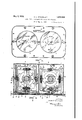
My invention is illustrated in the accompanying drawings forming a part of this application, in which Figure 1 is a front view of the panel;
Figure 2 is a section along theline 22 of Figure 1;
Figure 3 is a section along the line 33 of Figure 2; 1
Figure 4 is a section along the line 44 of Figure 2; and
Figures 5 and 6 are side elevations of the gyroscope-supporting members.
In carrying out my invention, I provide a casing 1 (see Figure 2) which is divided into two compartments A and B by a partition 2. In each compartment I mount a gyro scope, and will hereinafter refer to the gyroscope 3 as being in compartment A and gyroscope 1 as being in compartment B.
The casing 1 is covered by a front panel 5, and this panel is provided with two dials 6 and 7 which constitute a climb dial and a bank dial. Pointers or indicators 8 and 9 of climb. The pointer 9 shows a rear view of the airplane, and the wings of this airplane indicate the angle or degree of banking. This type of pointer in place of the usual arrowhead is not so likely to confuse the pilot, and moreover a combination of both show the exact position of the plane while in the air.
If desired, the panel may be provided with a spirit level 12, green lights 13, and red lights 14:. These lights are for the purpose of informing the pilot whether he is flying upside down or not, because if it were not for thesenlights the plane might take a complete turn in the air and if the vision were obscured by fog, storm, or the like, the pilot would have no means of quickly determining whether he is flying right side up or not. A simple arrangement such as the lights 13 and 14 would obviate errors which might prove fatal.
I will first describe the climb indicator mechanism. Reference to Figure 4 shows a fragmentary view of the bottom 15 of the casing 1. This bottom carries guide flanges 16, and these form a dove-tail slot for receiving a dove-tail projection 17 of a frame 18. The frame is locked in place by a setscrew 19. I In the aligned bearings 20 of the frame, I mount one member 21 of a gimbal. The other member 22 of the gimbal is mounted in bearings indicated generally at 23 (see Figure 1) which extend at right angles to the bearings 20. The member 22 supports the'gyroscope 3, and the axis of the gyroscope is vertically disposed. This construction gives a universal movement between the gyroscope and the casing 1 and permits the gyroscope to remain vertical irrespective of the angular positions assumed by the easing 1.
A bevel gear 24 is rigidly connected to the member 21 and is turned therewith. This gear meshes with a bevel gear 25 which in turn is mounted upon the shaft 10. It will therefore be seen from this construction that the gyroscope 3 will remain vertical, that the casing 1 will be turned into angular positions when the airplane is so turned, and that the relative movement between the casing and the gyroscope will cause a swinging of the member 21 with respect to the casing, and this movement will be imparted to the gears 24 and 25 and will cause the indicator 8 to register the exact angle at which'the casing 1 is tipped with respect to the horizontal. The pilot glances at the indicator and knows at what angle his plane is climbing or descending. p
v The gyroscope 4 and its mountings are somewhat the same as those for the gyroscope 3. The compartment B has flanges 26 forming a dove-tail slot for receiving a' dove-tail projection 27 of a frame 28. A set screw 29 locks the frame in place. This frame is provided with aligned bearings 30, only one of which appears in Figure 4 due to the fact that the other is disposed directly in back. The frame also carries a small bearing 31. In the aligned bearings 30 I mount one member 32 of a 'gimbal. This member carries bearings 34 which support the other member 35 of the gimbal. The gyroscope is carried by the member 35, and its axis extends verticallyl The members 22 and 35 are weighted at their bottoms asshown at 22 and 35' in Figures 5'and 6 in order that the gyroscopes 3 and 4 will always tend to remain in vertical positions.
The connections between the indicator 9 and the gyroscope consists of the shaft 11, bevel gears 36, 37 and 38, and the gimbal comprising. the members 32 and 35. When the casing 1 inclines laterally due to the-banking of the aeroplane the gyroscope 4 remains vertical, and there is therefore a relative movement between the gyroscope, the member 32, and the frame 28. This movement causes a turning 'of the-gear 38, which in turn moves the indicator 9. Both .gyroscopes are so mounted within their respective gimbals as to permit the aircraft to loop the loop or to corkscrew through the air without af-' footing the instrument in any way.
In Figures 2 and 3 I show the way the gyroscopes are connected with a source of current. Lead-in wires 39 and 40 are electrically connected to pins 41 and 42 respectively by brushes 43 and 44. Wires/45 and 46- lead from the pins to brushes 47 and 48. These \in turn are electrically connected to pins 49 rious parts of the device, the operation thereof may be readily understood.
The panel 5 is placed at any convenient ready to function as soon as current is delivered-to the gyroscopes 3 and 4. In case the pilottakes a number of loops, the indicator 8 will appear to make a series of complete circles. The indicator 8 will also show when the airplane is climbing or going down. Should the pilot cause his plane to corkscrew through the air, the indicator 9 would take a number of complete revolutions. Any banking at the turns .will also be shown by the indicator 9. The pilot can ascertain his exact position in the air by glancing at both indicators. The device is simple in construction, and provides novel and eflicient means for showing at a glance the angle at which the aircraft is disposed with' respect to the ground. I
' A turn indicator is mounted on dial 7 and comprises a weighted hand rotatablymounted on the shaft 11.- Any turning of the plane will cause the arm to swing by centrifugal force. to indicate the turn eventhough the plane is notbanking. It is obvious that the device can be attached to other craft such as a submarine.
Although I'have shown and described oneembodiment of my invention, it is to be understood that the same is susceptible of various changes, and I reserve the right .to employ such changes as may come within the scope of the appended claim.
I claim:
A bank, turn and climb indicator for aircraft comprising ,acasing securable to'the aircraft and having a pair of dials disposed close to each other and in substantially the same plane, a pointer for each dial, one of the pointers being in the shape of a side view of an airplane and the other pointer being in the shape of a rear view of the same airplane, and means disposed within said housing for automatically swinging said pointers with respect to said housing for continuously indicating respectively the longitudinal and lateral attitude of the craft.
' CASPERE. SCHUELLER.
Priority Applications (1)
| Application Number | Priority Date | Filing Date | Title |
|---|---|---|---|
| US279488A US1856436A (en) | 1928-05-21 | 1928-05-21 | Bank, turn, and climb indicator for aircraft |
Applications Claiming Priority (1)
| Application Number | Priority Date | Filing Date | Title |
|---|---|---|---|
| US279488A US1856436A (en) | 1928-05-21 | 1928-05-21 | Bank, turn, and climb indicator for aircraft |
Publications (1)
| Publication Number | Publication Date |
|---|---|
| US1856436A true US1856436A (en) | 1932-05-03 |
Family
ID=23069197
Family Applications (1)
| Application Number | Title | Priority Date | Filing Date |
|---|---|---|---|
| US279488A Expired - Lifetime US1856436A (en) | 1928-05-21 | 1928-05-21 | Bank, turn, and climb indicator for aircraft |
Country Status (1)
| Country | Link |
|---|---|
| US (1) | US1856436A (en) |
Cited By (8)
| Publication number | Priority date | Publication date | Assignee | Title |
|---|---|---|---|---|
| US2487809A (en) * | 1944-09-28 | 1949-11-15 | George W Hoover | Combined attitude and directional instrument for aircraft |
| US2489294A (en) * | 1947-06-21 | 1949-11-29 | Kenyon Gyro & Electronics Corp | Flight attitude indicating instrument |
| US2924885A (en) * | 1955-03-28 | 1960-02-16 | Lear Inc | Aircraft indicating instrument and system |
| US3455030A (en) * | 1966-07-11 | 1969-07-15 | Aircraft Radio Corp | Directional gyroscope |
| US3701092A (en) * | 1970-11-09 | 1972-10-24 | Albert Howard Hasbrook | Vehicular attitude-control display |
| US3723963A (en) * | 1969-04-03 | 1973-03-27 | Aircraft Instr Inc | Aircraft gyrohorizon indicator with signal lamp positional attitude indicating means |
| US4151656A (en) * | 1977-09-12 | 1979-05-01 | Eastman Kodak Company | Manually manipulatable gyroscope-stabilized indicating apparatus and method for its use |
| US20060124390A1 (en) * | 2004-12-03 | 2006-06-15 | Bellsouth Intellectual Property Corporation | Angle meter and spirit level |
-
1928
- 1928-05-21 US US279488A patent/US1856436A/en not_active Expired - Lifetime
Cited By (9)
| Publication number | Priority date | Publication date | Assignee | Title |
|---|---|---|---|---|
| US2487809A (en) * | 1944-09-28 | 1949-11-15 | George W Hoover | Combined attitude and directional instrument for aircraft |
| US2489294A (en) * | 1947-06-21 | 1949-11-29 | Kenyon Gyro & Electronics Corp | Flight attitude indicating instrument |
| US2924885A (en) * | 1955-03-28 | 1960-02-16 | Lear Inc | Aircraft indicating instrument and system |
| US3455030A (en) * | 1966-07-11 | 1969-07-15 | Aircraft Radio Corp | Directional gyroscope |
| US3723963A (en) * | 1969-04-03 | 1973-03-27 | Aircraft Instr Inc | Aircraft gyrohorizon indicator with signal lamp positional attitude indicating means |
| US3701092A (en) * | 1970-11-09 | 1972-10-24 | Albert Howard Hasbrook | Vehicular attitude-control display |
| US4151656A (en) * | 1977-09-12 | 1979-05-01 | Eastman Kodak Company | Manually manipulatable gyroscope-stabilized indicating apparatus and method for its use |
| US20060124390A1 (en) * | 2004-12-03 | 2006-06-15 | Bellsouth Intellectual Property Corporation | Angle meter and spirit level |
| US7392593B2 (en) * | 2004-12-03 | 2008-07-01 | At&T Delaware Intellectual Property, Inc. | Angle meter and spirit level |
Similar Documents
| Publication | Publication Date | Title |
|---|---|---|
| US2260396A (en) | Direction indicator | |
| US1856436A (en) | Bank, turn, and climb indicator for aircraft | |
| US2178637A (en) | Means and method of instrument indication in airplanes and the like | |
| US2758377A (en) | Navigation instrument | |
| US1361367A (en) | Aeroplane level-indicator | |
| US1573028A (en) | Stabilized bomb sight | |
| US1980886A (en) | Device indicating the flying attitude of aircraft | |
| US1376727A (en) | Direction-indicator for air and marine craft | |
| US2395250A (en) | Turn, bank, and climb indicator | |
| US2489294A (en) | Flight attitude indicating instrument | |
| US1760163A (en) | Flight-attitude indicator | |
| US2044150A (en) | Artificial horizon | |
| US2367667A (en) | Flight indicator for aircraft | |
| US2487809A (en) | Combined attitude and directional instrument for aircraft | |
| US1306882A (en) | clarke | |
| US2582796A (en) | Attitude-indicating instrument for air and other craft | |
| US3282242A (en) | Artificial horizon instrument for aircraft operation | |
| US2043168A (en) | Combined gyro-compass and artificial horizon | |
| US2333983A (en) | Indicator control mechanism | |
| US1935740A (en) | Aeroplane instrument | |
| US2017900A (en) | Combination magnetic compass and level indicator | |
| USRE20701E (en) | Ball gyro horizon | |
| US2053182A (en) | Bank and turn indicator | |
| US1302580A (en) | Inclination-indicator. | |
| US2176197A (en) | Earth inductor compass |