US185642A - Improvement in corn-planters - Google Patents
Improvement in corn-planters Download PDFInfo
- Publication number
- US185642A US185642A US185642DA US185642A US 185642 A US185642 A US 185642A US 185642D A US185642D A US 185642DA US 185642 A US185642 A US 185642A
- Authority
- US
- United States
- Prior art keywords
- wheel
- corn
- wheels
- lever
- planters
- Prior art date
- Legal status (The legal status is an assumption and is not a legal conclusion. Google has not performed a legal analysis and makes no representation as to the accuracy of the status listed.)
- Expired - Lifetime
Links
- 239000003550 marker Substances 0.000 description 5
Images
Classifications
-
- A—HUMAN NECESSITIES
- A01—AGRICULTURE; FORESTRY; ANIMAL HUSBANDRY; HUNTING; TRAPPING; FISHING
- A01C—PLANTING; SOWING; FERTILISING
- A01C5/00—Making or covering furrows or holes for sowing, planting or manuring
- A01C5/06—Machines for making or covering drills or furrows for sowing or planting
- A01C5/062—Devices for making drills or furrows
- A01C5/064—Devices for making drills or furrows with rotating tools
Definitions
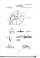
- Figure 1 is a top view, showing the position of the hoppers, index-wheel, and drivers seat, also the attachment of the elastic dropping-tubes.
- Fig. 2 is a perspective view of the wheels and axle, and showing the position of the check-row mechanism and marker,
- Fig. 3 is a side elevation of the machine.
- Fig. 4 is a plan view of the plate upon which the dropping-plates A turn.
- Fig. 5 is a sectional view of the same.
- Fig. 6 is an edge view of the dropping-plates. showing the teeth on the under side.
- Fig. 7 is a vertical section of the seed-spout or tooth, and showing the valve.
- Fig. 8 is a detached View of the axle with driving Wheel or pinion attached and showing the index-wheel X and shifting-clutch W in section.
- Fig. 9 is a perspective of the shifting-clutch.
- a A, Fig. 1 are the dropping-plates, B B the wheels, and C U the thills; E, the drivers seat; D D, the shovels or coverers; F, hand ⁇ lever; F1, foot-lever.
- H2 is the axle, having the drive-gear or pinion G sliding thereon, to shift or change the distance of drop. H H are the seed-hoppers. I I are posts or standards, for the purpose of sighting to keep the machine in line While check-row dropping.
- J is the shifting-lever, working in connection with the circular plate R2, for the purpose of shifting the driving-gear G in and out of gear or into the different rows of teeth on the index-wheel X.
- the plate R2 has holes for the reception of a pin in the end ot' the shiftinglever J, in order to hold the wheel G in any required position.
- K K are flexible tubes, which connect the dropping-plates or the tube S, on plate T, Fig. 4, with the tubes or drill-teeth P P', Fig. 2.
- L, Fig. 2 is a marking device, which is operated by means of pins M on the side of the wheel B.
- N, Fig. 2 is the lever by means of which the valves V, Fig. 7, are operated. This lever is also tripped by means of the pins M on the side of the Wheel B.
- the upright rod o' is also attached to the valve in the tube P, and through the means of the rod h, crank R, rod S, crank R', and rod h', connects with upright rod U, attached to the valve in the tooth P.
- the arms C are attached to the hubs of the Wheels in front, and have the coverers D attached to their rear ends.
- the arms D (best seen in Fig. 3) are pivoted at their forward ends to the arms C', and are pivoted to the teeth or spouts at g.
- the arms C' attached to the hubs of the wheels and carrying the hand-leverF and foot-lever F in front, and extending back in rear of the Wheels, carry the coverers D D, tubes or spouts P P', and marker L, allot' which can be lifted simultaneously at will by the operator.
- the Wheel Gr slides upon the axle, and is operated by means of' the clutch W, to shift it into mesh with any one of the different rows of teeth in the index-Wheel X, which communicates motion to the drop-plates A .A through the rods or shafts d and pinions K2, the distance apart of the drop being adjusted by means of the wheel G, in connection with the index-wheel X.
Landscapes
- Life Sciences & Earth Sciences (AREA)
- Soil Sciences (AREA)
- Environmental Sciences (AREA)
- Sowing (AREA)
Description
ZSheets-Sheetl. J. R. MATLACK.
CORN-PLANTER. N0.185,64Z. Patented Dec.26,1876.
THE GRAPHIC CD.N4Y
m'rrm STATES *PATEN Error;
JOSEPH R. MATLAGK, OF OOXS MILLS, INDIANA.
IMPROVEMENT IN CORN-PLANTERS.
Specitication forming part of Letters Patent No. 185,642, dated December 26, 1876 application filed January 14, 1876.
To all whom it may concern.:
Be it known that I, JosEPn R. MATLAGK, of Goxs Mills, county ot' Wayne and State of Indiana, have invented certain Improvements in Corn-Planters, of which the following is a specification My invention relates to that class of cornplanters which are placed upon wheels and may be made to plant two or three rows at a time, either in check-rows or drills, as Will be fully described hereafter.
Figure 1 is a top view, showing the position of the hoppers, index-wheel, and drivers seat, also the attachment of the elastic dropping-tubes. Fig. 2 is a perspective view of the wheels and axle, and showing the position of the check-row mechanism and marker,
and also the driving-gear on the axle. Fig.4
3 is a side elevation of the machine. Fig. 4 is a plan view of the plate upon which the dropping-plates A turn. Fig. 5 is a sectional view of the same. Fig. 6 is an edge view of the dropping-plates. showing the teeth on the under side. Fig. 7 is a vertical section of the seed-spout or tooth, and showing the valve. Fig. 8 is a detached View of the axle with driving Wheel or pinion attached and showing the index-wheel X and shifting-clutch W in section. Fig. 9 is a perspective of the shifting-clutch.
A A, Fig. 1, are the dropping-plates, B B the wheels, and C U the thills; E, the drivers seat; D D, the shovels or coverers; F, hand` lever; F1, foot-lever. H2 is the axle, having the drive-gear or pinion G sliding thereon, to shift or change the distance of drop. H H are the seed-hoppers. I I are posts or standards, for the purpose of sighting to keep the machine in line While check-row dropping. J is the shifting-lever, working in connection with the circular plate R2, for the purpose of shifting the driving-gear G in and out of gear or into the different rows of teeth on the index-wheel X. The plate R2 has holes for the reception of a pin in the end ot' the shiftinglever J, in order to hold the wheel G in any required position. K K are flexible tubes, which connect the dropping-plates or the tube S, on plate T, Fig. 4, with the tubes or drill-teeth P P', Fig. 2. L, Fig. 2, is a marking device, which is operated by means of pins M on the side of the wheel B. N, Fig. 2, is the lever by means of which the valves V, Fig. 7, are operated. This lever is also tripped by means of the pins M on the side of the Wheel B. The upright rod o' is also attached to the valve in the tube P, and through the means of the rod h, crank R, rod S, crank R', and rod h', connects with upright rod U, attached to the valve in the tooth P.
Thus it will be seen that the pins M, striking the lever N, operate both valves simultaneously by means of the above-described arrangement of the rods. The arms C are attached to the hubs of the Wheels in front, and have the coverers D attached to their rear ends. The arms D (best seen in Fig. 3) are pivoted at their forward ends to the arms C', and are pivoted to the teeth or spouts at g.
Thus it will be seen that the arms C', attached to the hubs of the wheels and carrying the hand-leverF and foot-lever F in front, and extending back in rear of the Wheels, carry the coverers D D, tubes or spouts P P', and marker L, allot' Which can be lifted simultaneously at will by the operator. The Wheel Gr slides upon the axle, and is operated by means of' the clutch W, to shift it into mesh with any one of the different rows of teeth in the index-Wheel X, which communicates motion to the drop-plates A .A through the rods or shafts d and pinions K2, the distance apart of the drop being adjusted by means of the wheel G, in connection with the index-wheel X.
Having thus fully described my invention, what I claim and desire to secure by Letters Patent, is
1. The combination and arrangement of the arms C', attached to the hubs of the ground-wheels, and carrying the hand-lever F and foot-lever F in t'ront, and extending back in rear of the Wheels and carrying the tubes P P, and coverers D D, and marker L, substantially as described.
2. The arms C', attached to the Wheels, as shown, and carrying the coverers D and marker L, in combination with the pins M, for operating the marker, substantially as described.
M, with wheel B', substantially as and for th purpose specified.
JOSEPH R. MATLAOK.
Witnesses EDWARD R. MATTHEWS,
W. THOMAS.
Publications (1)
| Publication Number | Publication Date |
|---|---|
| US185642A true US185642A (en) | 1876-12-26 |
Family
ID=2255048
Family Applications (1)
| Application Number | Title | Priority Date | Filing Date |
|---|---|---|---|
| US185642D Expired - Lifetime US185642A (en) | Improvement in corn-planters |
Country Status (1)
| Country | Link |
|---|---|
| US (1) | US185642A (en) |
-
0
- US US185642D patent/US185642A/en not_active Expired - Lifetime
Similar Documents
| Publication | Publication Date | Title |
|---|---|---|
| US185642A (en) | Improvement in corn-planters | |
| US210214A (en) | Improvement in combined drill and corn-planter | |
| US348204A (en) | Combined plow and planting mechanism | |
| US500909A (en) | Corn-planter | |
| US602554A (en) | Corn-planter | |
| US274351A (en) | Corn-planter | |
| US323324A (en) | -eaynee | |
| US966326A (en) | Combined corn and cotton planter. | |
| US225095A (en) | Corn-drill | |
| US189581A (en) | Improvement in dropping and marking attachments for corn-planters | |
| US335075A (en) | Check-row attachment for corn-planters | |
| US476141A (en) | Combined harrow an d corn-planter | |
| US83943A (en) | Alfred edmister | |
| US186766A (en) | Improvement in corn-planters | |
| US216163A (en) | Improvement in seed-planters | |
| US452411A (en) | Corn-planter | |
| US472246A (en) | Check-row corn-planter | |
| US339124A (en) | Corn-planter | |
| US290070A (en) | Corn-planter | |
| US81548A (en) | smith | |
| US1073749A (en) | Corn-planter. | |
| US653705A (en) | Check-row corn-planter. | |
| US444030A (en) | Corn-planter | |
| US202196A (en) | Improvement in corn-planter attachments | |
| US300557A (en) | foesteb |