US1856426A - Feeder for pulverizers and the like - Google Patents
Feeder for pulverizers and the like Download PDFInfo
- Publication number
- US1856426A US1856426A US1856426DA US1856426A US 1856426 A US1856426 A US 1856426A US 1856426D A US1856426D A US 1856426DA US 1856426 A US1856426 A US 1856426A
- Authority
- US
- United States
- Prior art keywords
- housing
- wall
- feed
- opening
- gate
- Prior art date
- Legal status (The legal status is an assumption and is not a legal conclusion. Google has not performed a legal analysis and makes no representation as to the accuracy of the status listed.)
- Expired - Lifetime
Links
- 239000000463 material Substances 0.000 description 15
- 239000003245 coal Substances 0.000 description 4
- 239000012634 fragment Substances 0.000 description 2
- 239000012530 fluid Substances 0.000 description 1
- 238000011010 flushing procedure Methods 0.000 description 1
- VKYKSIONXSXAKP-UHFFFAOYSA-N hexamethylenetetramine Chemical compound C1N(C2)CN3CN1CN2C3 VKYKSIONXSXAKP-UHFFFAOYSA-N 0.000 description 1
- 230000003340 mental effect Effects 0.000 description 1
- 238000012986 modification Methods 0.000 description 1
- 239000004575 stone Substances 0.000 description 1
- 239000002023 wood Substances 0.000 description 1
Images
Classifications
-
- A—HUMAN NECESSITIES
- A01—AGRICULTURE; FORESTRY; ANIMAL HUSBANDRY; HUNTING; TRAPPING; FISHING
- A01C—PLANTING; SOWING; FERTILISING
- A01C7/00—Sowing
- A01C7/08—Broadcast seeders; Seeders depositing seeds in rows
- A01C7/16—Seeders with other distributing devices, e.g. brushes, discs, screws or slides
-
- B—PERFORMING OPERATIONS; TRANSPORTING
- B02—CRUSHING, PULVERISING, OR DISINTEGRATING; PREPARATORY TREATMENT OF GRAIN FOR MILLING
- B02C—CRUSHING, PULVERISING, OR DISINTEGRATING IN GENERAL; MILLING GRAIN
- B02C23/00—Auxiliary methods or auxiliary devices or accessories specially adapted for crushing or disintegrating not provided for in preceding groups or not specially adapted to apparatus covered by a single preceding group
- B02C23/02—Feeding devices
Definitions
- My invention relates to feeding mechanism for apparatus, such for example, as coal pulverizers, and has for its object the provision of apparatus of the character designated which shall be simple of design, reliable in operation and which shall include an e improved means for varying the rate of feed to the pulverizer.
- My invention relates particularly to that 1 type of feeding mechanism embodying a horizontal rotary table for delivering material, and has for its particular-object the provision of an improved means for varying V the rate of delivery from the rotary table.
- a still further object of my invention is to provide an improved material delivery means for cooperation with the rotary table of a feeding mechanism, and a simple readily accessible gate mechanism for cooperation with the delivery means to regulate the rate of flow from the rotary table.
- my invention consists in a circular, horizontal, rotary feed table with a housing for the same secured to and opening into the apparatus to be fed.
- a feed hopper is positioned above the housing over the table and the housing is divided by a radial wall above the table, directly under the hopper, so that materialis delivered only into a segment of the housing.
- the dividing wall extends radially inward from the housing to approximately the center of the table and has its lower edge directly above the table.
- the interior of the housing is open above the table between the inner end of the radial wall and the outer wall to permit material to be carried therethrough upon rotation of the table.
- An arcuate gate is'positioned directly in front of the opening just described and has a radial arm pivoted in the housing in front of-the opening.
- a slot is provided in the side of the housing for the end of the arcuate gate whereby the gate may be turned about its pivot to vary the opening.
- a removable plate is provided in the housing adjacent the gate whereby ready access may be had to the interior for the purpose of clearing the opening of any foreign matter.
- Fig. 1 is a vertical sectional view of a feeder embodying my invention and taken along the lines II of Fig. 2;
- Fig. 2 is a sectional view taken along the lines IIII of Fig. 1.
- a fragment of a pulverizer which may 6 be of any approved type and which is representative of apparatus requiring accurate feed control. It will be obvious, however, that my improved feeding mechanism may be employed with apparatus other than pulverizers.
- a cylindrical housing 12 Secured to the pulverizer 10 and opening thereinto at 11 is a cylindrical housing 12.
- a rotary feed table 13 Positioned in the lower part of the housing 12 is a rotary feed table 13 having a shaft 14 journalled in a suitable bearing 16 and driven through a worm gear 17 and worm 18 by any suitable power means, not shown.
- a suitable feed hopper Positioned above the table 13 is a suitable feed hopper, a fragment of which is shown at 21.
- a radial wall 23 extends inwardly toward the'center of the table 13 and just clears the table so that material on the table is not carried under the wall 23.
- the radial wall 23 separates a segment 19 of the housing from the remainder, in which segment material to be pulverized is delivered from the hopper 21.
- the side of the segment 19 from the inner end of the wall 23 to the wall 22 of the housing is left open to permit the discharge of mater al from'the segment upon rotation of the table 13 in the direction shown by the arrows. hen the table is thus rotated the wall 23 serves as a scraper for removing material from the table to discharge it through the opening 11 into the pulverizer 10.
- an arcuate gate 26 In order to vary the amount of material delivered. through the side opening of the seg ment 19,1 mount in front of the side opening an arcuate gate 26.
- the gate 26 s provided with a radial arm 27 pivoted at 28 to the covor 29 of the cylindrical casing 12.
- a handle 31 is secured to the upper end of the pivot pin 28 whereby the gate may be swung to any desired position.
- a slot 32 is provided in the outer wall of the casing 12 to permit the outer end of the arcuate gate 26 to move outwardly of the casing when being opened.
- I form the casing 12 with removable segment 38 directly in front of the gate 26 and 25, metrically opposite to the opening in the drawings that the point of discharge of ma-v terial from the table 13 is substantially diachamber 19 and the arcuategate 26. With this arrangement, dry material being delivered from thehopper 21 to the chamber 19 will not run or flush across the table 13 to the discharge side of-the table without rotation of the table.
- housing'for the table a radial wall in the housing forming with-the outer wall a seg? 7 mental feed chamberland a segmental dis. 3 charge chamber. extending downwardly to I v V V the table onone side thereofioneside of said feed chamber beingzopen forfthe discharge of material therethrough to the discharge I chamber, and a gatevpivoted to one side of the housing and adapted to swing across the a openinginlthesegmental feedchamberto li'mf-f V it said opening.
- a feeder mechanism for pulverizer for pulverizers a cylindrical housing openinginto the pulverizer, a horizontalrotary feed table disposed within the housing, a segmental feed chamber in the housing extending downwardly to the table on one'side thereof, a radial wall in the housing forming one side of the segmental feed chamber and arranged directly above the table to serve as a scraper to remove material therefrom, one side of the chamber bemgopen abovethe table for the discharge of material therefrom, and an arcuate gate pivotedon one side of the housing to swing directly in front of the opening.
- a cylindrical vertically extending housing opening into the pulverizer a rotary horizontal feed table disposed in the lower part of the housing, a segmental feed chamber arranged above the table and extending down wardly thereto, one wall of the housing forming a. lower side wall of the chamber, a second lower side wall extending radially inward above the table to form a scraper for remov- ,ing material from the table, an arcuate gate for the open side of the chamber, a radial arm for theagate exten'dingforwardly therefrom, and pivot means for the radial arm,
- a feeder mechanisinfor apulverizer a cylindrical vertically extending housing opening into. the pulverizer, a rotary horizontal feed table disposed in thel'ower part of the housing, a segmentalfeed chamber in the housing above the table and extending downwardly thereto, one wall of the housing forming a lower side wall of the feed cham her, portion of the wall in'the housing extending radially inward above the table to form another will of the feed chamber and serving as a scraper for removing material gate extending forwardly therefrom, pivot 'means for the radial arm, and means for removably' securing a part of the housing'wallinfront of the gate.
Landscapes
- Life Sciences & Earth Sciences (AREA)
- Soil Sciences (AREA)
- Environmental Sciences (AREA)
- Engineering & Computer Science (AREA)
- Food Science & Technology (AREA)
- Crushing And Grinding (AREA)
Description
- May 3, 1932- w. w. PETTIBONE 1,856,426
FEEDER FOR PULVERIZERS AND THE LIKE Filed Sept. 29, 1930 INVENTOR Wzflier W Petf ibane W/T/VE5$- W M/% 2 fi ATTORNEYS Patented May 3, 1932 WALTER W. PETTIBONE, OF BIRMINGHAM, ALABAMA FEEDER FOR PULVERIZERS AND THE LIKE Application filed September 29, 1930. Serial No 485,187.
My invention relates to feeding mechanism for apparatus, such for example, as coal pulverizers, and has for its object the provision of apparatus of the character designated which shall be simple of design, reliable in operation and which shall include an e improved means for varying the rate of feed to the pulverizer. My invention relates particularly to that 1 type of feeding mechanism embodying a horizontal rotary table for delivering material, and has for its particular-object the provision of an improved means for varying V the rate of delivery from the rotary table. A still further object of my invention is to provide an improved material delivery means for cooperation with the rotary table of a feeding mechanism, and a simple readily accessible gate mechanism for cooperation with the delivery means to regulate the rate of flow from the rotary table.
Briefly, my invention consists in a circular, horizontal, rotary feed table with a housing for the same secured to and opening into the apparatus to be fed. A feed hopper is positioned above the housing over the table and the housing is divided by a radial wall above the table, directly under the hopper, so that materialis delivered only into a segment of the housing. The dividing wall extends radially inward from the housing to approximately the center of the table and has its lower edge directly above the table. The interior of the housing is open above the table between the inner end of the radial wall and the outer wall to permit material to be carried therethrough upon rotation of the table. An arcuate gate is'positioned directly in front of the opening just described and has a radial arm pivoted in the housing in front of-the opening. A slot is provided in the side of the housing for the end of the arcuate gate whereby the gate may be turned about its pivot to vary the opening. A removable plate is provided in the housing adjacent the gate whereby ready access may be had to the interior for the purpose of clearing the opening of any foreign matter.
vention is illustrated in the accompanying Apparatus embodying features of my indrawings forming a part of this application, in which: 7
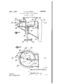
Fig. 1 is a vertical sectional view of a feeder embodying my invention and taken along the lines II of Fig. 2; and
Fig. 2 is a sectional view taken along the lines IIII of Fig. 1.
Referring to the drawings for a better understanding of my invention, I show in Fig. 1 at 10 a fragment of a pulverizer which may 6 be of any approved type and which is representative of apparatus requiring accurate feed control. It will be obvious, however, that my improved feeding mechanism may be employed with apparatus other than pulverizers. Secured to the pulverizer 10 and opening thereinto at 11 is a cylindrical housing 12. Positioned in the lower part of the housing 12 is a rotary feed table 13 having a shaft 14 journalled in a suitable bearing 16 and driven through a worm gear 17 and worm 18 by any suitable power means, not shown.
Positioned above the table 13 is a suitable feed hopper, a fragment of which is shown at 21. A radial wall 23 extends inwardly toward the'center of the table 13 and just clears the table so that material on the table is not carried under the wall 23. The radial wall 23 separates a segment 19 of the housing from the remainder, in which segment material to be pulverized is delivered from the hopper 21. The side of the segment 19 from the inner end of the wall 23 to the wall 22 of the housing is left open to permit the discharge of mater al from'the segment upon rotation of the table 13 in the direction shown by the arrows. hen the table is thus rotated the wall 23 serves as a scraper for removing material from the table to discharge it through the opening 11 into the pulverizer 10.
In order to vary the amount of material delivered. through the side opening of the seg ment 19,1 mount in front of the side opening an arcuate gate 26. The gate 26 s provided with a radial arm 27 pivoted at 28 to the covor 29 of the cylindrical casing 12. A handle 31 is secured to the upper end of the pivot pin 28 whereby the gate may be swung to any desired position. A slot 32 is provided in the outer wall of the casing 12 to permit the outer end of the arcuate gate 26 to move outwardly of the casing when being opened.
' 'It sometimes occurs in the operation of pulverizers of this'character that foreign matter such as blocks of wood, stone, etc., are introduced with the coal to the feeding mechanism and must be cleared ofi the rotary table 13.
In order to readily accomplish this purpose,
I form the casing 12 with removable segment 38 directly in front of the gate 26 and 25, metrically opposite to the opening in the drawings that the point of discharge of ma-v terial from the table 13 is substantially diachamber 19 and the arcuategate 26. With this arrangement, dry material being delivered from thehopper 21 to the chamber 19 will not run or flush across the table 13 to the discharge side of-the table without rotation of the table.
I have found, in the operationoffeeding Y mechanism involving a'rotary table that,
across the table in a manner similar to a fluid.
with thoroughly dry material, such as dry coal, there is a tendency for the coal to run -With my improved apparatus the relative positions of the opening and the dzscharge edge, together with the necessity for the ma- 02 terial to change its direction of travel before reaching the discharge edge prevent-s this flushing action.
0116 form, it will be obvious to those skilled ceptible of various changes and modificati ons, without departing from the spirit thereof and I des re, therefore, that only such limitations shall be placed thereupon as 'are imposed by the prior art or as are specifically setforth in the appended claims.
: WhatI claimis: 1 A
' 1. Ina fe-ede1'*-mecl1anism, a circular, ro-
tary,"horizontally disposed feed table, a
housing'for the table a radial wall in the housing forming with-the outer wall a seg? 7 mental feed chamberland a segmental dis. 3 charge chamber. extending downwardly to I v V V the table onone side thereofioneside of said feed chamber beingzopen forfthe discharge of material therethrough to the discharge I chamber, and a gatevpivoted to one side of the housing and adapted to swing across the a openinginlthesegmental feedchamberto li'mf-f V it said opening.
While I have shown my invention-in. but,
- in the art that" it is not so limited, but is sus- I the housing,
2. In a feeder mechanism for pulverizers a cylindrical housing openinginto the pulverizer, a horizontalrotary feed table disposed within the housing,a segmental feed chamber in the housing extending downwardly to the table on one'side thereof, a radial wall in the housing forming one side of the segmental feed chamber and arranged directly above the table to serve as a scraper to remove material therefrom, one side of the chamber bemgopen abovethe table for the discharge of material therefrom, and an arcuate gate pivotedon one side of the housing to swing directly in front of the opening.
3. In a feeder mechanism for a pulverizer,
a cylindrical vertically extending housing opening into the pulverizer, a rotary horizontal feed table disposed in the lower part of the housing, a segmental feed chamber arranged above the table and extending down wardly thereto, one wall of the housing forming a. lower side wall of the chamber, a second lower side wall extending radially inward above the table to form a scraper for remov- ,ing material from the table, an arcuate gate for the open side of the chamber, a radial arm for theagate exten'dingforwardly therefrom, and pivot means for the radial arm,
4.1 In a feeder mechanisinfor apulverizer, a cylindrical vertically extending housing opening into. the pulverizer, a rotary horizontal feed table disposed in thel'ower part of the housing, a segmentalfeed chamber in the housing above the table and extending downwardly thereto, one wall of the housing forming a lower side wall of the feed cham her, portion of the wall in'the housing extending radially inward above the table to form another will of the feed chamber and serving as a scraper for removing material gate extending forwardly therefrom, pivot 'means for the radial arm, and means for removably' securing a part of the housing'wallinfront of the gate. I i .f
5. In a feeder mechanism for a pulverizer, a cylindrical: vertically "extending housing opening into the pulverizenga rotary horizontal feed table disposed mam lower part of a I segmental 'feed chamber arranged above the table and extending downwardly thereto, one wall of the housing formin a lower 'side wallof the "chamber-,fa secend lower side wall extending radiallyinward above the table to form a scraper for removing material from the table,-and an adjustable gate extending from theoutside of the housing inwardly across the open side'of V thechamber; V V 1 In testimony whereof Iia-fiix my'signature.
7 Y IVALTE WtPETTIBONE'
Publications (1)
| Publication Number | Publication Date |
|---|---|
| US1856426A true US1856426A (en) | 1932-05-03 |
Family
ID=3423715
Family Applications (1)
| Application Number | Title | Priority Date | Filing Date |
|---|---|---|---|
| US1856426D Expired - Lifetime US1856426A (en) | Feeder for pulverizers and the like |
Country Status (1)
| Country | Link |
|---|---|
| US (1) | US1856426A (en) |
Cited By (1)
| Publication number | Priority date | Publication date | Assignee | Title |
|---|---|---|---|---|
| US2608372A (en) * | 1943-04-12 | 1952-08-26 | Jl Ferguson Co | Weighing and filling machine |
-
0
- US US1856426D patent/US1856426A/en not_active Expired - Lifetime
Cited By (1)
| Publication number | Priority date | Publication date | Assignee | Title |
|---|---|---|---|---|
| US2608372A (en) * | 1943-04-12 | 1952-08-26 | Jl Ferguson Co | Weighing and filling machine |
Similar Documents
| Publication | Publication Date | Title |
|---|---|---|
| US1911718A (en) | Hatotkr mill fob | |
| US1437863A (en) | Feeding device | |
| US2173414A (en) | Feeder | |
| US1856426A (en) | Feeder for pulverizers and the like | |
| US581908A (en) | Joseph franklin gent and richard thomas gent | |
| US3391831A (en) | Dry solids fertilizer applicator | |
| US1679398A (en) | Disk feeder | |
| US1611675A (en) | Scalper and cut-off attachment for feed mills | |
| US2420966A (en) | Grain and roughage cutter and grinder | |
| US1006573A (en) | Hay-pulverizer. | |
| US1464621A (en) | Apparatus for mixing and breaking up earth and fertilizer | |
| GB500952A (en) | Improvements in or relating to mixing or grinding mills and the like | |
| US2314706A (en) | Grain grinder gate valve | |
| US1760906A (en) | Mixing machine for viscous and granular materials | |
| US2135343A (en) | Grain separator | |
| US1628546A (en) | Fertilizer-distributing machine | |
| US2098618A (en) | Machine for treating seed grain | |
| US1447722A (en) | Feeding device for winnowing machines | |
| US1463777A (en) | Percentage feeder | |
| US2059482A (en) | Feeder | |
| US1944902A (en) | Feeder for pulverized materials | |
| US1134600A (en) | Fuel-feeding mechanism for furnaces. | |
| US2146061A (en) | Conveyer | |
| US2045709A (en) | Material feeder | |
| US1679241A (en) | Akd mixing- apparatus |