US1856423A - Fuse plug panel and block - Google Patents
Fuse plug panel and block Download PDFInfo
- Publication number
- US1856423A US1856423A US259627A US25962728A US1856423A US 1856423 A US1856423 A US 1856423A US 259627 A US259627 A US 259627A US 25962728 A US25962728 A US 25962728A US 1856423 A US1856423 A US 1856423A
- Authority
- US
- United States
- Prior art keywords
- block
- load circuit
- bars
- fuse
- fuse plug
- Prior art date
- Legal status (The legal status is an assumption and is not a legal conclusion. Google has not performed a legal analysis and makes no representation as to the accuracy of the status listed.)
- Expired - Lifetime
Links
- 230000007935 neutral effect Effects 0.000 description 4
- 238000010276 construction Methods 0.000 description 2
- 238000009413 insulation Methods 0.000 description 1
Images
Classifications
-
- H—ELECTRICITY
- H01—ELECTRIC ELEMENTS
- H01H—ELECTRIC SWITCHES; RELAYS; SELECTORS; EMERGENCY PROTECTIVE DEVICES
- H01H85/00—Protective devices in which the current flows through a part of fusible material and this current is interrupted by displacement of the fusible material when this current becomes excessive
- H01H85/02—Details
- H01H85/20—Bases for supporting the fuse; Separate parts thereof
- H01H2085/2075—Junction box, having holders integrated with several other holders in a particular wiring layout
Definitions
- This invention has for its object a fuse plug block which is particularly simple in construction and readily applicable to a panel and by which several difierent combinations of wiring can be readily made.
- Figures 1 and 2 are respectively a plan and end elevation of this fuse block and the panel on which it is mounted.
- Figure 3 is an inverted view of the block.
- Figure 4 is an end elevation, partly in section of parts seen in Figure 3, the section be ing taken on line 44, Figure 3.
- Figures 5, 6, 7, and 8 are diagrammatic views of the different combinations of wir- I designates the panel and 2 the block, these being of insulation.
- T he block is preferably formed with a lengthwise passage therethrough and the bus bars 3, 4 are located on opposite sides of this passage 7.
- the load circuit bars and also the branches 9, 10 of the neutral bar are provided with suitable wire binding devices 26, 27.
- FIG 5 a two circuit two wire double fuse combination is shown in which one leg of the load circuit is connected to the load circuit bar 23 and the other leg to the load circuit bar 25, and the one leg of the other circuit is likewise connected to the load circuit bar 22 and the load circuit bar 2&, the circuits being designated with the numerals 1 and 2 at the fuses in said circuits.
- FIG 6 a four circuit two wire single fuse combination is shown, the circuits being numbered 1, 2, 3, 4 at the fuses in said circuit.
- one leg of the load circuit is connected to the load circuit bar 23 and the other leg to a binding device on the branch 9 of the bus bar 8.
- the other three load circuits are likewise connected to the load circuit bars 22 and branch 9, load circuit bar 2& and branch 10 and load circuit bar 25 and branch 10.
- FIG 7 a two circuit two wire double fuse combination is shown in which the legs of the load circuit are connected respectively to the load circuit bars 24, 25 and to load circuit bars 22, 23.
- each leg of the load circuit is connected to one of the load circuit bars 25 and to one of the branches of the third bus bar.
- a fuse plug panel and block the combination of a base, a block mountable on the base, a pair of substantially parallel outside bus bars mounted on the lower side of the block, the block also having a ledge 011 opposite sides thereof and a neutral bus bar having branches on said ledge, load circuit bars mounted on the lower side of the block at an angle to the outside bus bars, fuse plug terminals mounted on the block and means for electrically and mechanically connecting the members of each pair of terminals'to one of the outside bus bars and to one of the load circuit bars.
- a fuse plug panel and block the combination of a base, a block mounted on the base, a pair of substantially parallel outside bus bars mounted on the lower side of the block, the block also having a ledge on oppo- 1 site sides thereof and extending parallel to the outside bus bars, a neutral bus bar having terminals on said ledges, load circuit bars mounted between the base and the block at an angle to the outside bus bars and extending and having terminals beyond the edges of the block, fuse receptacles carried by the block, each fuse receptacle having one of its terminals mechanically and electrically connected to the outside bus bar and its complemental terminals mechanically and electrically connected to the load circuit bar, and means extending through the base and coacting with the load circuit bars for securing the block to the base.
Landscapes
- Multi-Conductor Connections (AREA)
Description
y 1932 E. A. QLLEY 1,856,423
FUSE PLUG PANEL AND BLOCK Filed March 7, 1928 2 Sheets-Sheet 1 z /9 /Z k 49 A? Z0 Z0 /7 A? Z5 Q l I 1 N VEN TOR.
ATTORNEYS.
May 3, 1932. E, A, OLLEY 1,856,423
FUSE PLUG PANEL AND BLOCK Filed March '7, 1928 2 Sheets-Sheet 2 INVENTOR.
" i a g 5 4 A TTORNEYS.
Patented May 3, 1932 UNITED STATES PATENT OFFICE EDWIN A. OLLEY, OF SYRACUSE, NEW YORK, ASSIGNOR TO OROUSE-HINDS COMPANY, OF SYRACUSE, NEW YORK, A CORPORATION OF NEW YORK FUSE PLUG PANEL AND BLOCK Application filed March 7, 1928. Serial No. 259,627.
This invention has for its object a fuse plug block which is particularly simple in construction and readily applicable to a panel and by which several difierent combinations of wiring can be readily made.
The invention consists in the novel features and in the combinations and constructions hereinafter set forth and claimed.
In describing this invention, reference is bad to the accompanying drawings in which like characters designate corresponding parts in all the views.
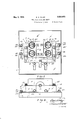
Figures 1 and 2 are respectively a plan and end elevation of this fuse block and the panel on which it is mounted.
Figure 3 is an inverted view of the block.
Figure 4 is an end elevation, partly in section of parts seen in Figure 3, the section be ing taken on line 44, Figure 3.
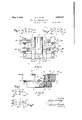
Figures 5, 6, 7, and 8 are diagrammatic views of the different combinations of wir- I designates the panel and 2 the block, these being of insulation.
3 and 4-. designate respectively the outside bus bars, these being mounted on the lower side of the block 1 and arranged substantially parallel to each other and being located in channels 5, 6 in the block. T he block is preferably formed with a lengthwise passage therethrough and the bus bars 3, 4 are located on opposite sides of this passage 7.
8 is a third bus bar having branches 9, 10
overlying horizontal ledges 11 and 12 on the lateral sides of the block located midway between the top and bottom of the block, the branches being secured to the block by screws 13 extending upwardly from the lower side of the block into the branches.
14, 15, 16 and 17 designate fuse receptacles mounted on the block, the terminals 18 and 19 of each receptacle being mechanically and electrically connected respectively by screws 20 and 21 to one of the outside bus bars 3, 4 and to one of the load circuit bars and hence being mechanically secured by the screws 20, 21 to the block.
22, 23, 24 and 25 designate load circuit bars mounted on the lower side of the block 2 and extending beyond the lateral sides thereof,
these being arranged substantially flush with the lower face of the block 2, the load circuit bars and also the branches 9, 10 of the neutral bar are provided with suitable wire binding devices 26, 27.
The block is mechanically secured to the panel 1 by screws 28 extending through the panel from the rear side thereof and threading into holes 29 in the load circuit bars. The screws 28 thus mechanically secure the block to the base and the screws 20 and 21 mechanically secure the outside bus bars and the load circuit bars and the fuse to the block as well as electrically connect the fuse terminals with the bus bars and the load circuit bars.
Owing to the relative arrangement of the bus bars, load circuit bars and fuses, these parts are compactly located on a comparatively small block and several wiring combinations are possible.
In Figure 5, a two circuit two wire double fuse combination is shown in which one leg of the load circuit is connected to the load circuit bar 23 and the other leg to the load circuit bar 25, and the one leg of the other circuit is likewise connected to the load circuit bar 22 and the load circuit bar 2&, the circuits being designated with the numerals 1 and 2 at the fuses in said circuits.
In Figure 6, a four circuit two wire single fuse combination is shown, the circuits being numbered 1, 2, 3, 4 at the fuses in said circuit. In Figure 6, one leg of the load circuit is connected to the load circuit bar 23 and the other leg to a binding device on the branch 9 of the bus bar 8. The other three load circuits are likewise connected to the load circuit bars 22 and branch 9, load circuit bar 2& and branch 10 and load circuit bar 25 and branch 10.
In Figure 7, a two circuit two wire double fuse combination is shown in which the legs of the load circuit are connected respectively to the load circuit bars 24, 25 and to load circuit bars 22, 23.
In Figure 8, a four circuit two wire single fuse combination is shown in which each leg of the load circuit is connected to one of the load circuit bars 25 and to one of the branches of the third bus bar.
What I claim is:
1. In a fuse plug panel and block, the combination of a base, a block mountable on the base, a pair of substantially parallel outside bus bars mounted on the lower side of the block, the block also having a ledge 011 opposite sides thereof and a neutral bus bar having branches on said ledge, load circuit bars mounted on the lower side of the block at an angle to the outside bus bars, fuse plug terminals mounted on the block and means for electrically and mechanically connecting the members of each pair of terminals'to one of the outside bus bars and to one of the load circuit bars.
2. In a fuse plug panel and block, the
combination of a base, a block mountable on the base, a pair of substantially parallel outside bus bars mounted on the lower side of the block, the block also having aledge on opposite sides thereof and a neutral bus bar having branches on said ledge, load circuit bars mounted on the lower side of the block at an angle to the outside bus bars, fuse plug terminals mounted on the block and means for electrically and mechanically connecting the members of each pair of terminals to one of the outside bus bars and to one of the load circuit bars, the outside bus bars, and the load circuit bars being substantially flush with the lower side of the block and screws extending through the base and threading into some of said bars for mechanically securing the block to the base.
3. In a fuse plug panel and block, the combination of a base, a block mounted on the base, a pair of substantially parallel outside bus bars mounted on the lower side of the block, the block also having a ledge on oppo- 1 site sides thereof and extending parallel to the outside bus bars, a neutral bus bar having terminals on said ledges, load circuit bars mounted between the base and the block at an angle to the outside bus bars and extending and having terminals beyond the edges of the block, fuse receptacles carried by the block, each fuse receptacle having one of its terminals mechanically and electrically connected to the outside bus bar and its complemental terminals mechanically and electrically connected to the load circuit bar, and means extending through the base and coacting with the load circuit bars for securing the block to the base.
In testimony whereof, I'have hereunto signed my name, at Syracuse, in the county,
of Onondaga, and in the State of New York. this 15th day of December, 1927.
EDWIN A. OLLEY.
Priority Applications (1)
| Application Number | Priority Date | Filing Date | Title |
|---|---|---|---|
| US259627A US1856423A (en) | 1928-03-07 | 1928-03-07 | Fuse plug panel and block |
Applications Claiming Priority (1)
| Application Number | Priority Date | Filing Date | Title |
|---|---|---|---|
| US259627A US1856423A (en) | 1928-03-07 | 1928-03-07 | Fuse plug panel and block |
Publications (1)
| Publication Number | Publication Date |
|---|---|
| US1856423A true US1856423A (en) | 1932-05-03 |
Family
ID=22985698
Family Applications (1)
| Application Number | Title | Priority Date | Filing Date |
|---|---|---|---|
| US259627A Expired - Lifetime US1856423A (en) | 1928-03-07 | 1928-03-07 | Fuse plug panel and block |
Country Status (1)
| Country | Link |
|---|---|
| US (1) | US1856423A (en) |
Cited By (14)
| Publication number | Priority date | Publication date | Assignee | Title |
|---|---|---|---|---|
| US2623930A (en) * | 1950-04-07 | 1952-12-30 | Fed Electric Prod Co | Distribution unit for three-wire systems |
| US2786162A (en) * | 1951-03-06 | 1957-03-19 | Fed Electric Prod Co | Circuit breaker service equipment |
| USD406111S (en) * | 1998-01-09 | 1999-02-23 | Esoteric Audio U.S.A. Inc. | Fuse block |
| USD408368S (en) * | 1998-01-09 | 1999-04-20 | Esoteric Audio U.S.A., Inc. | Fuse block |
| USD584697S1 (en) | 2008-04-23 | 2009-01-13 | Littelfuse, Inc. | Vehicle electrical center subassembly |
| USD585390S1 (en) | 2008-04-23 | 2009-01-27 | Littelfuse, Inc. | Four-leafed vehicle electrical center assembly |
| USD585389S1 (en) | 2008-04-23 | 2009-01-27 | Littelfuse, Inc. | Two-leafed vehicle electrical center subassembly |
| USD585392S1 (en) | 2008-04-23 | 2009-01-27 | Littelfuse, Inc. | Vehicle electrical center assembly |
| USD585391S1 (en) | 2008-04-23 | 2009-01-27 | Littlefuse Inc. | Two-leafed vehicle electrical center assembly |
| USD585846S1 (en) | 2008-04-23 | 2009-02-03 | Littelfuse, Inc. | Four-leafed vehicle electrical center subassembly |
| USD590353S1 (en) | 2008-04-23 | 2009-04-14 | Littelfuse, Inc. | Vehicle electrical center cover |
| US20090269951A1 (en) * | 2008-04-23 | 2009-10-29 | Littelfuse, Inc. | Flexible power distribution module |
| US20110084549A1 (en) * | 2008-04-23 | 2011-04-14 | Littelfuse, Inc. | Flexible power distribution module |
| US9415730B2 (en) | 2008-04-23 | 2016-08-16 | Littlefuse, Inc. | Flexible power distribution module cover assembly |
-
1928
- 1928-03-07 US US259627A patent/US1856423A/en not_active Expired - Lifetime
Cited By (15)
| Publication number | Priority date | Publication date | Assignee | Title |
|---|---|---|---|---|
| US2623930A (en) * | 1950-04-07 | 1952-12-30 | Fed Electric Prod Co | Distribution unit for three-wire systems |
| US2786162A (en) * | 1951-03-06 | 1957-03-19 | Fed Electric Prod Co | Circuit breaker service equipment |
| USD406111S (en) * | 1998-01-09 | 1999-02-23 | Esoteric Audio U.S.A. Inc. | Fuse block |
| USD408368S (en) * | 1998-01-09 | 1999-04-20 | Esoteric Audio U.S.A., Inc. | Fuse block |
| USD584697S1 (en) | 2008-04-23 | 2009-01-13 | Littelfuse, Inc. | Vehicle electrical center subassembly |
| USD585390S1 (en) | 2008-04-23 | 2009-01-27 | Littelfuse, Inc. | Four-leafed vehicle electrical center assembly |
| USD585389S1 (en) | 2008-04-23 | 2009-01-27 | Littelfuse, Inc. | Two-leafed vehicle electrical center subassembly |
| USD585392S1 (en) | 2008-04-23 | 2009-01-27 | Littelfuse, Inc. | Vehicle electrical center assembly |
| USD585391S1 (en) | 2008-04-23 | 2009-01-27 | Littlefuse Inc. | Two-leafed vehicle electrical center assembly |
| USD585846S1 (en) | 2008-04-23 | 2009-02-03 | Littelfuse, Inc. | Four-leafed vehicle electrical center subassembly |
| USD590353S1 (en) | 2008-04-23 | 2009-04-14 | Littelfuse, Inc. | Vehicle electrical center cover |
| US20090269951A1 (en) * | 2008-04-23 | 2009-10-29 | Littelfuse, Inc. | Flexible power distribution module |
| US20110084549A1 (en) * | 2008-04-23 | 2011-04-14 | Littelfuse, Inc. | Flexible power distribution module |
| US7955133B2 (en) | 2008-04-23 | 2011-06-07 | Littelfuse, Inc. | Flexible power distribution module |
| US9415730B2 (en) | 2008-04-23 | 2016-08-16 | Littlefuse, Inc. | Flexible power distribution module cover assembly |
Similar Documents
| Publication | Publication Date | Title |
|---|---|---|
| US1856423A (en) | Fuse plug panel and block | |
| US2007174A (en) | Panel board system | |
| US1700582A (en) | Electrical fuse block | |
| US3184645A (en) | Electrical circuit assembly | |
| US1821987A (en) | Fuse block terminal structure | |
| US3192446A (en) | Distribution panel | |
| US3605061A (en) | Printed circuit board | |
| NO144255B (en) | A branch box with a connection plug. | |
| US1023326A (en) | Electric cut-out. | |
| US1888854A (en) | Fuse block and fuse therefor | |
| US1714790A (en) | Fuse block | |
| US2165203A (en) | Panel board | |
| US1028254A (en) | Meter-testing cut-out. | |
| US1736028A (en) | Electric panel or distribution board | |
| US1905121A (en) | Panel-board section | |
| US1744209A (en) | Electrical panel board | |
| US977123A (en) | Panel-board. | |
| US1815038A (en) | Panel board | |
| US1296999A (en) | Panel-board construction. | |
| US1864353A (en) | Attachment plug cap | |
| US1307019A (en) | Edwin a | |
| US1321486A (en) | Panel-board | |
| US330644A (en) | Assigistoe to the | |
| US1220608A (en) | Electric fitting. | |
| US1520452A (en) | Panel board |