US1856422A - Friction shock absorbing mechanism - Google Patents
Friction shock absorbing mechanism Download PDFInfo
- Publication number
- US1856422A US1856422A US269932A US26993228A US1856422A US 1856422 A US1856422 A US 1856422A US 269932 A US269932 A US 269932A US 26993228 A US26993228 A US 26993228A US 1856422 A US1856422 A US 1856422A
- Authority
- US
- United States
- Prior art keywords
- friction
- plates
- post
- wedge
- shock absorbing
- Prior art date
- Legal status (The legal status is an assumption and is not a legal conclusion. Google has not performed a legal analysis and makes no representation as to the accuracy of the status listed.)
- Expired - Lifetime
Links
- 230000007246 mechanism Effects 0.000 title description 49
- 230000035939 shock Effects 0.000 title description 20
- 230000006835 compression Effects 0.000 description 5
- 238000007906 compression Methods 0.000 description 5
- 230000009699 differential effect Effects 0.000 description 5
- 238000000926 separation method Methods 0.000 description 2
- 101150100212 Manf gene Proteins 0.000 description 1
- 230000003190 augmentative effect Effects 0.000 description 1
- 238000006073 displacement reaction Methods 0.000 description 1
- 230000000977 initiatory effect Effects 0.000 description 1
- 238000012986 modification Methods 0.000 description 1
- 230000004048 modification Effects 0.000 description 1
Images
Classifications
-
- B—PERFORMING OPERATIONS; TRANSPORTING
- B61—RAILWAYS
- B61G—COUPLINGS; DRAUGHT AND BUFFING APPLIANCES
- B61G9/00—Draw-gear
- B61G9/04—Draw-gear combined with buffing appliances
- B61G9/10—Draw-gear combined with buffing appliances with separate mechanical friction shock-absorbers
Definitions
- Onefobject of the invention is to 4provide a friction Shock. absorbing mechanism espe- ,Cial'ly adapted for railway draft riggings,
- yAnother object of the invention is to provide, in a friction shock absorbing mecha- IliSm ofthe character indicated, including relatively movable friction, plates, a central friction post, a, friction shell enclosing the plates, and' friction wedge elements cooperatingwith the plates and post, differential action to provide high. capacity, wherein the differential action. ijs effected by providing friction surfaces on the post andshell which are inclined with respect to the direction of the applied force.. ⁇
- A; further object of the invention i's-to provide in a friction.
- Shock absorbing mechanism ⁇ of the double-ended type including relatively movable friction plates and friction wedge means cooperating with the pla-tes, a central friction post cooperating with the friction wedge means, wherein the post has the friction surfaces thereof carried by detachable end sections to provide for renewal of the friction surfaces by substituting new end sections for end sections which have become worn.
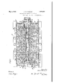
- Figure 1 is a horizontal, longitudinal sectional view through a portion of a draft rigging of a railwayl car', illustrating my improvements in, connection therewith.
- Figure 21 is a vertical, transversel Serial N0. 269,932.
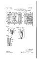
- Figure 8 is a longitudinal, vertical sectionall view of the front end portion of the shock absorbing mechanism illustrated in Figure 1 and coriresponding substantially to the line 3-8 of said ligure.
- Figures t, 5, and 6 are detailed, perspective views, respectively, of one of the end sections of the friction post, one
- My improved shock absorbing mechanism which is of the double-ended friction type, is disposed within the yokel and the yoke in turn is supported by a detachable saddle plate 15, fixed to4 the ⁇ lower flanges of the draft sills in any suitable manf ner, the saine being shown assecured by bolts.
- My improved friction shock absorbing mechanism proper comprises, broadly, front and rear friction shells or casings A-A, two
- the front and rear friction casings or shells A are each in the form of a substantially rectangular boXlike member, having longitudinally disposed spaced side walls 16-.16, horizontally disposed, spaced top and bottom walls 17-17, and a vertical' outer end wall 18.
- the end wall 18 of each shell A cooperatesY with the corresponding stop lugs of the draft sills in the manner of the usual main follower.
- the side walls16 of each friction casing A are provided with opposed, interior friction surfaces 1.9-1.9, diverging inwardly ofthe mechanism.
- the friction post C is disposed centrally of 22 of this shell.
- each casing A is provided with an inwardly extending hollow boss 22 on the end wall* 18 thereof, which receives the corresponding end' of the retainer bolt.
- the yhead of the bolt is disposed in the boss of the front follower casing ⁇ A and a retaining .disc is interposed between the head of the bolt and the inner wall of the boss.
- the nut of the bolt is disposed in the hollow boss of the rear friction casing ⁇ A and a disc is also in' erposed between the nut and the inner wall of the hollow boss It will be evident that the retainer bolt thus holds the parts-of the friction post assembled.
- the end sections 21. of the post eX- tend through openings in the bosses 22 of the two casings A and have their outer ends d1- rectly engaging the retaining discs.
- the retaining discs are thustightly clamped to the sections of thepostand cooperate with the vbosses 22 ⁇ of the casings A to limit outward separation of said casmgs.
- the endsections 21 ofthe friction post C areeach provided with a pair of friction surfaces 23-23 on the opposite sides thereof,
- the plates of one of said sets being indicated by 2l-2lland'theplates of theotherset bei ing indicated by 25--25.
- one of the plates 24 of-each group is'dlsposed innermost, while one of the plates 25 of saidgroup isdisposed outermost and'cooperates with the friction surfaces 19-19 -of the friction casings or'shells A' at the same side of the mechanism.
- the friction plates24 and 25 have the opposite end portions thereof inclined inwardly with respect to the longitudinal "axis of the mechanism,'so as 'to properly cooperate with'the inwardly diverging friction surfaces ofthe frontand rear friction shells.
- Each ofthe yplates 24 Vand 25 of the two groups is provided with an inturned flange 'section y26 .atgoneendjthereof., VThe plates of each group lare so arranged that the yflanges of the set-'of plates 24 are disposed at one end of the-mechanism, while the flanges of the Y.
- plates 25v are disposed at the opposite end of the mechanism. rlhe two groups of plates B are reversely arranged so that the flanges of the plates 24 of ,one group are located at the same end of the mechanism as the flanges of the plates 25 of the other group. ⁇ As shown in Figure 1, the yflanges of the plates of-each set overhang each other" and those of the plates 24 of one group overlap one of the friction shoes of the 'pair at one end of the mechanism, whilethose of the plates 25 of the same group overhang the friction shoes at the same side ofthepair at the other end of the mechanism. The plates are thus restored to normal position by the outward movement of the friction shoes through the flanges 26.
- the inturned flanges of the plates are spaced from the end walls of the corresponding casings to permit relativel movement of the Casin-gs and plates during initial action of the mechanism.
- the inturned ends of thel plates arespaced a proper distance from the extremities of the adjacent lplates to permit the necessary fullcompression of the mechanism.
- the friction wedge blocks D are four'in number and are arranged in pairs atV opposite ends of the mechanism, the blocks of each 'pair' being disposed on opposite'sides of the corresponding end sections4 ⁇ 21 ⁇ of the friction post C.
- Each wedge block D is provided with a flat end face 27 which directly bears upon the hollow boss 22 .ofthe corresponding frictionV shell.
- each wedge block D is centrally' cut away on the inner side, as indicated Vat 28,-to accommodate the side portion of the corresponding end section 21 of the friction post.
- Thecut away section 28 is provided with a vertically disv posed flat friction surface 29 which cooper? ates' with the friction surface 23 at thesame side of the section 21.
- each bloclt D has a flat wedge face 30 which cooperates with the corresponding friction shoe E.
- the friction shoes E are arranged in pairs at the front and rear ends of the mechanism and cooperate with thecorresponding wedge blocks D.
- f v f Y ⁇ Each friction shoe E is provided with 'a flatv outer friction surfacel which cooperates with the innermost ofthe friction plates of the corresponding group B. l,At the forward end.the bloclr'E is'cut'away andthe cut away sectionl thereof is provided with a flatV wedge face 32 which cooperates vwith the wedge face 30 of the corresponding wedge Vbloclr D.
- On the inner side, therear end portion of the friction shoe is provided withtop and bottom inwardly projecting arms 33-33 which embrace the friction post and serve to guide the friction shoe longitudinally ⁇ of the mechanism.v
- the malnspring resistance comprises? an inner coil and a heavier outer coil, the inner y"coil surrounding Ythe central column 2O of the friction post and both coils having their opposite ends bearing directly on the inner ends of the frontend rear pairs lof friction shoes.
- the spring resistance F is placed under a substantial initial compression so that the wedge friction shoes are held apart land compensation for wear of the various friction-and wedge faces will be had by the outward movement of the shoes with respect to the remaining elements of the mechanism.
- the parts of the mechanism are restored to normal position when the actuating force is reduced by the expansive action of the main ⁇ spring resistance F, and outward movement of the shells or casing A is limited by the retainer bolt G through the medium of the discs at the opposite ends thereof which cooperate with the bosses 22 of the frontand rear friction shells.
- sectional friction post having removable end portions which carry the friction surfaces
- the parts of the mechanism may be readily renewedwhen the friction .surfaces of the post become worn, -by substituting new end sections, thus adding greatly to the life of the gear.
- a friction shock absorbing .mechanism the combination with front and rear friction casings relatively movable toward and away from each other; of two groups of relatively movable intercalated friction plates, disposed at opposite sides of the mechanism and having frictional engagement with the casings, said plates being moved relatively to each other by said casings; a central friction post having friction surfaces at opposite ends thereof; friction wedge members at opposite ends of the mechanism slidable on the friction surfaces of the post; friction shoes interposed between the wedge member and the groupsof plates, said shoes having sliding contact with said groups of plates and wedging engagement with the friction wedge members; and a spring resistance between the post and groups of plates surrounding and enclosing said post and yieldingly opposing relative movement of t ie friction shoes.
- a friction shock absorbing mecha ⁇ nism the combination with relatively movable Vfront and rear follower acting means, one of said follower acting means being in Y tional engagement with the friction surfaces the form of a friction shell; of two groups-of relatively Ymovable, Vintercalated friction plates, disposed at opposite sides of the mechanism and having sliding frictional engagement with ythe friction shell; a central friction post; friction wedge means adapted to receive the actuating force, said friction wedge means being interposed between the post and plates and having frictional engagement with both the post and shell; and spring resista ce means surrounding said post and disposed between the same and the friction plates, said spring resistance opposing in-v ward movement of the friction wedge means.
- a friction 'shock absorbing mechanism the combination with front and rear friction casings relatively movable towa:1 and away from each other, said casiiigs having opposed, interior, inwardly diverging friction surfaces; of a central friction post having friction surfaces at the opposite ends thereof, the friction surfaces at each end of the post being disposed on opposite sides thereof and diverging inwardly of the mechanism; two groups of relatively movable, in-
- tercalated frictionk plates disposed at opposite sides of the mechanism and 'ico-operating with the friction surfaces of the front and rear casings a pair of wedge blocks movable with each friction casing and having fricat the corresponding end of vthe friction post;
- Vln a friction shock absorbing mechanism,rthe combination with'front and rear friction casin'gs relatively movable rtoward and away from each other, said casings hav-V ing opposed, interior. friction surfaces, inclined to the longitudinal airis of the Vmechanism; of a central friction post vtapered at opposite ends, said tapered ends being provided with friction surfaces on'the opposite sides thereof; two groups of relatively movable, intercalated friction plates disposed at opposite sides of the mechanism .and cooperating with'the friction surfaces of tliefriction casings; a pair of wedge blocks movableA with each friction Vcasingand having fricl tional engagementwith the friction surfaces at the corresponding end of the friction post; Va pair of friction shoes-at each end of the mechanism, said shoes having wedging kengagement with the wedge members at the corresponding end of the Vmechanism and frictional engagement with ,the friction plates; resistance means snr.-
- the plates of said groups being relatively movable by movement of said friction shells; friction wedge means at each end ofthe mechanism, interposed between thepost and groups of plates and having engagement'with the friction surfaces of the post and,plates,'said friction ward movement thereof; a central friction post; friction wedge members at one end of vthe post, cooperating therewith; friction shoes engaged-bythe friction wedge members and having frictional engagement with the friction plates and spring resistance 'means surrounding said postfand yieldingly opposing inward movement v.of the friction shoes.
- a friction shock absorbing mechanism the combination with relatively movable followers; of a group of relatively movable, longitudinally Y disposed l intercalated frictionV plates, said' plates being bowed lengthwise in the same direction, saidplates ybeing movable relatively to each other by said followers; friction means cooperating with the plates and opposing lateral displacement thereof in one direction, said friction means being movable lengthwise l of the plates; means o actuated yby said 'followers upon relative approach thereof for forcing said plates against vthe friction means; and means yieldingly opposing relative movement of the friction meansiand plates.
Landscapes
- Engineering & Computer Science (AREA)
- Mechanical Engineering (AREA)
- Vibration Prevention Devices (AREA)
Description
May 3, 1932- J. F. ocoNNoR FRICTION SHOCK ABSORBING MECHNISM Filed April 14, 1928 2 Sheets-Sheei l RNN QQ N mQQ May 3, 1932 J. o'coNNoR 1,856,422 l FRICTION SHOCK ABSORBING MECHANISM Filed April 14, 1928 2 She'ecS--Sheefl 2 Y, is
Patented May 3, 1932 g unirse! srArEs PATENT OFFICE JGHN F. OCONNOBr, OF CHICAGO, ILLINOIS, ASSIGNOR TO W. H. MINER, ING., 0F CHICAGO,
' ILLINOIS, A GORPORATION OF DELAWARE FRICTION SHOCK ABSQRBING MECHANISM Application filed April 14, 1928- 'his invention relates to improvements vin friction shock absorbing mechanisms.
Onefobject of the invention is to 4provide a friction Shock. absorbing mechanism espe- ,Cial'ly adapted for railway draft riggings,
having high frictional capacity produced by a plurality of relatively movable intercalated friction vmembers, including friction wedge elements, friction shoes, friction shells, a friction post, and a main, spring' resistance opposing movement ofthe friction plates and members, wherein the post is disposed centrally ofl the mechanism, thereby providing a maximum amount of spring space to accommodate the main spring resistance, thus permitting the use of' a high capacity spring surrounding the friction post.
yAnother object of the invention is to provide, in a friction shock absorbing mecha- IliSm ofthe character indicated, including relatively movable friction, plates, a central friction post, a, friction shell enclosing the plates, and' friction wedge elements cooperatingwith the plates and post, differential action to provide high. capacity, wherein the differential action. ijs effected by providing friction surfaces on the post andshell which are inclined with respect to the direction of the applied force..`
A; further object of the invention i's-to provide in a friction. Shock absorbing mechanism` of the double-ended type, including relatively movable friction plates and friction wedge means cooperating with the pla-tes, a central friction post cooperating with the friction wedge means, wherein the post has the friction surfaces thereof carried by detachable end sections to provide for renewal of the friction surfaces by substituting new end sections for end sections which have become worn. v.
Other and further objects of the invention will more clearly appear from the description and' claims hereinafter following.
In the drawings, forming a part of this specification, Figure 1 is a horizontal, longitudinal sectional view through a portion of a draft rigging of a railwayl car', illustrating my improvements in, connection therewith. Figure 21 is a vertical, transversel Serial N0. 269,932.
sectional View, corresponding substantially to the line 2-2 of Figure 1. Figure 8 is a longitudinal, vertical sectionall view of the front end portion of the shock absorbing mechanism illustrated in Figure 1 and coriresponding substantially to the line 3-8 of said ligure. And Figures t, 5, and 6 are detailed, perspective views, respectively, of one of the end sections of the friction post, one
of the friction shoes and one of the wedge known form. My improved shock absorbing mechanism, which is of the double-ended friction type, is disposed within the yokel and the yoke in turn is supported by a detachable saddle plate 15, fixed to4 the` lower flanges of the draft sills in any suitable manf ner, the saine being shown assecured by bolts.
My improved friction shock absorbing mechanism proper comprises, broadly, front and rear friction shells or casings A-A, two
groups of friction plates B-B', a central friction post C, front and rear pairs of Wedge friction blocks D-D, frontand rear pairs of friction shoes E-E, a main spring'resistance F, and a retainer bolt Gr.
The front and rear friction casings or shells A are each in the form of a substantially rectangular boXlike member, having longitudinally disposed spaced side walls 16-.16, horizontally disposed, spaced top and bottom walls 17-17, and a vertical' outer end wall 18. The end wall 18 of each shell A cooperatesY with the corresponding stop lugs of the draft sills in the manner of the usual main follower. The side walls16 of each friction casing A are provided with opposed, interior friction surfaces 1.9-1.9, diverging inwardly ofthe mechanism.
The friction post C is disposed centrally of 22 of this shell. Y
chored to the respectivecasings A. As shown,
each casing A is provided with an inwardly extending hollow boss 22 on the end wall* 18 thereof, which receives the corresponding end' of the retainer bolt. y
As shown yin Figure 1, the yhead of the bolt is disposed in the boss of the front follower casing `A and a retaining .disc is interposed between the head of the bolt and the inner wall of the boss. The nut of the bolt is disposed in the hollow boss of the rear friction casing` A and a disc is also in' erposed between the nut and the inner wall of the hollow boss It will be evident that the retainer bolt thus holds the parts-of the friction post assembled. The end sections 21. of the post eX- tend through openings in the bosses 22 of the two casings A and have their outer ends d1- rectly engaging the retaining discs. The retaining discs are thustightly clamped to the sections of thepostand cooperate with the vbosses 22`of the casings A to limit outward separation of said casmgs.
v The endsections 21 ofthe friction post C areeach provided with a pair of friction surfaces 23-23 on the opposite sides thereof,
which are inclined with respect to the longi- Y tudinal axis of themechanism and, as shown,. preferably diverge inwardly of the mecha- The friction plates "B yare arranged in two ,groups at opposite sides of themechanism,V
each group` comprising two-.sets of plates,
. the plates of one of said sets being indicated by 2l-2lland'theplates of theotherset bei ing indicated by 25--25. As'shown, one of the plates 24 of-each group is'dlsposed innermost, while one of the plates 25 of saidgroup isdisposed outermost and'cooperates with the friction surfaces 19-19 -of the friction casings or'shells A' at the same side of the mechanism.
As clearly illustrated in Figure 1, the friction plates24 and 25 have the opposite end portions thereof inclined inwardly with respect to the longitudinal "axis of the mechanism,'so as 'to properly cooperate with'the inwardly diverging friction surfaces ofthe frontand rear friction shells.
Each ofthe yplates 24 Vand 25 of the two groups is provided with an inturned flange 'section y26 .atgoneendjthereof., VThe plates of each group lare so arranged that the yflanges of the set-'of plates 24 are disposed at one end of the-mechanism, while the flanges of the Y.
plates 25v are disposed at the opposite end of the mechanism. rlhe two groups of plates B are reversely arranged so that the flanges of the plates 24 of ,one group are located at the same end of the mechanism as the flanges of the plates 25 of the other group. `As shown in Figure 1, the yflanges of the plates of-each set overhang each other" and those of the plates 24 of one group overlap one of the friction shoes of the 'pair at one end of the mechanism, whilethose of the plates 25 of the same group overhang the friction shoes at the same side ofthepair at the other end of the mechanism. The plates are thus restored to normal position by the outward movement of the friction shoes through the flanges 26. As shown, the inturned flanges of the plates are spaced from the end walls of the corresponding casings to permit relativel movement of the Casin-gs and plates during initial action of the mechanism. The inturned ends of thel plates arespaced a proper distance from the extremities of the adjacent lplates to permit the necessary fullcompression of the mechanism.y j,
The friction wedge blocks D are four'in number and are arranged in pairs atV opposite ends of the mechanism, the blocks of each 'pair' being disposed on opposite'sides of the corresponding end sections4`21`of the friction post C. lEach wedge block D is provided with a flat end face 27 which directly bears upon the hollow boss 22 .ofthe corresponding frictionV shell. Y
As clearly disclosed in Figure 5V, each wedge block D is centrally' cut away on the inner side, as indicated Vat 28,-to accommodate the side portion of the corresponding end section 21 of the friction post. Thecut away section 28 is provided with a vertically disv posed flat friction surface 29 which cooper? ates' with the friction surface 23 at thesame side of the section 21. On the outer side, each bloclt D has a flat wedge face 30 which cooperates with the corresponding friction shoe E. Y
The friction shoes E are arranged in pairs at the front and rear ends of the mechanism and cooperate with thecorresponding wedge blocks D. f v f Y `Each friction shoe E is provided with 'a flatv outer friction surfacel which cooperates with the innermost ofthe friction plates of the corresponding group B. l,At the forward end.the bloclr'E is'cut'away andthe cut away sectionl thereof is provided with a flatV wedge face 32 which cooperates vwith the wedge face 30 of the corresponding wedge Vbloclr D. On the inner side, therear end portion of the friction shoe is provided withtop and bottom inwardly projecting arms 33-33 which embrace the friction post and serve to guide the friction shoe longitudinally` of the mechanism.v
The malnspring resistance comprises? an inner coil and a heavier outer coil, the inner y"coil surrounding Ythe central column 2O of the friction post and both coils having their opposite ends bearing directly on the inner ends of the frontend rear pairs lof friction shoes.
I By the central arrangement of the friction post and the spring resistance surrounding the same, it will be evident that the maximum `amount of spring space is made available,
thereby permitting the use of a spring resistance of exceptionally high capacity.
When the parts of the mechanism are assembled, the spring resistance F is placed under a substantial initial compression so that the wedge friction shoes are held apart land compensation for wear of the various friction-and wedge faces will be had by the outward movement of the shoes with respect to the remaining elements of the mechanism.
The operation of my improved shock absorbi-ng mechanism, assuming a compression stroke, is as follows The front and rear friction casings will be moved relatively toward eachother, carrying the wedge friction blocks D therewith. The latter will be forced to slide inwardly on the friction surfaces 23 lof the post and will also be forced into wedghas `been talren up and the walls of theshells directly engage the plates, the -same will be moved relatively to each other, thereby increasing the frictional resistance. During the compression of the mechanism, inward movement o-f the front and rear sets of friction shoes with respect to each other is op- Y posed by the mainspring resistance. Due
to the inwardly diverging relation of the fric- A-tion1 surfaces of the post and the `inwardly diverging relation of the Aopposed friction i surfaces of the front and rear friction shells,
a differential action will b e had, thereby ef- .C
greeting additional compression of the main spring resistance. Y p
lhe diferential action is effected bythe lateral `separation ofthe yfriction wedge 1 blocks D while moving on the diverging friction surfaces of the post, causing the wedge ,faces of the blocks D to slip on the wedge faces ofthe shoes E, thus forcing the shoes inwardly at a greater .rate vthan Athe wedge blocks. The differential -action is further augmented by the inwardly diverging relation ofthe friction surfaces of the friction shells. As the friction shells approach each l other,'the two groups of plates B will be forced laterally inwardly toward 'the central .axis of the mechanism, thereby displacing kthe frictionshoes inwardly also and causing additional movement of the shoes on the wedge faces of the blocks D. Inward movement of the friction shells A is finally limited by engagement of these shells with each other, thereby relieving the main spring resist-ance from undue compression.
The parts of the mechanism are restored to normal position when the actuating force is reduced by the expansive action of the main `spring resistance F, and outward movement of the shells or casing A is limited by the retainer bolt G through the medium of the discs at the opposite ends thereof which cooperate with the bosses 22 of the frontand rear friction shells.
F rom the preceding description, taken in connection with the drawings, it will be evident that I have provided a friction shock kabsorbing mechanism of the intercalated plate type which has exceptionally high capacity and differential action, wherein large fric'tional areas and the maximum amount of spring space for the spring resistance means is made available, thereby adding greatly to the capacity of the mechanism.
By providing the sectional friction post having removable end portions which carry the friction surfaces, the parts of the mechanism may be readily renewedwhen the friction .surfaces of the post become worn, -by substituting new end sections, thus adding greatly to the life of the gear.
While I have herein shown and described what I consider the preferred manner of carrying out my invention, the same is nierely illustrative and I contemplate all changes and modifications which come within the scope of the claims appended hereto.
I claim:
1. In a friction shock absorbing .mechanism, the combination with front and rear friction casings relatively movable toward and away from each other; of two groups of relatively movable intercalated friction plates, disposed at opposite sides of the mechanism and having frictional engagement with the casings, said plates being moved relatively to each other by said casings; a central friction post having friction surfaces at opposite ends thereof; friction wedge members at opposite ends of the mechanism slidable on the friction surfaces of the post; friction shoes interposed between the wedge member and the groupsof plates, said shoes having sliding contact with said groups of plates and wedging engagement with the friction wedge members; and a spring resistance between the post and groups of plates surrounding and enclosing said post and yieldingly opposing relative movement of t ie friction shoes.
2. In a friction shock absorbing mecha` nism, the combination with relatively movable Vfront and rear follower acting means, one of said follower acting means being in Y tional engagement with the friction surfaces the form of a friction shell; of two groups-of relatively Ymovable, Vintercalated friction plates, disposed at opposite sides of the mechanism and having sliding frictional engagement with ythe friction shell; a central friction post; friction wedge means adapted to receive the actuating force, said friction wedge means being interposed between the post and plates and having frictional engagement with both the post and shell; and spring resista ce means surrounding said post and disposed between the same and the friction plates, said spring resistance opposing in-v ward movement of the friction wedge means.
3. In a friction 'shock absorbing mechanism, the combination with front and rear friction casings relatively movable towa:1 and away from each other, said casiiigs having opposed, interior, inwardly diverging friction surfaces; of a central friction post having friction surfaces at the opposite ends thereof, the friction surfaces at each end of the post being disposed on opposite sides thereof and diverging inwardly of the mechanism; two groups of relatively movable, in-
tercalated frictionk plates, disposed at opposite sides of the mechanism and 'ico-operating with the friction surfaces of the front and rear casings a pair of wedge blocks movable with each friction casing and having fricat the corresponding end of vthe friction post;
Ya pair of friction shoes at each end of the mechanism, saidjshoes having wedging engagement with the wedge members at the corresponding end of the mechanism and lfrictional engagement with the yfriction plates; and a main spring resistance opposing relative approach of the frictiony shoes at the opposite ends of the mechanism.
l. Vln a friction shock absorbing mechanism,rthe combination with'front and rear friction casin'gs relatively movable rtoward and away from each other, said casings hav-V ing opposed, interior. friction surfaces, inclined to the longitudinal airis of the Vmechanism; of a central friction post vtapered at opposite ends, said tapered ends being provided with friction surfaces on'the opposite sides thereof; two groups of relatively movable, intercalated friction plates disposed at opposite sides of the mechanism .and cooperating with'the friction surfaces of tliefriction casings; a pair of wedge blocks movableA with each friction Vcasingand having fricl tional engagementwith the friction surfaces at the corresponding end of the friction post; Va pair of friction shoes-at each end of the mechanism, said shoes having wedging kengagement with the wedge members at the corresponding end of the Vmechanism and frictional engagement with ,the friction plates; resistance means snr.-
. roundingpthe post opposing inward movement of thefrictionshoes at `,opposite ends of the mechanism. v i v 5.7In afriction shock absorbing mechanism, the combination with frontand rear friction shells relativelymovable,toward and away froineach other; vof va central friction post comprising `a central column member and enlarged end sections, said end sections being provided with friction surfaces; a group of friction plates disposed. at each side of the mechanism, .the plates of said groups being relatively movable by movement of said friction shells; friction wedge means at each end ofthe mechanism, interposed between thepost and groups of plates and having engagement'with the friction surfaces of the post and,plates,'said friction ward movement thereof; a central friction post; friction wedge members at one end of vthe post, cooperating therewith; friction shoes engaged-bythe friction wedge members and having frictional engagement with the friction plates and spring resistance 'means surrounding said postfand yieldingly opposing inward movement v.of the friction shoes.
7. In a friction shock absorbing mechanism, the combination with relatively movable followers; of a group of relatively movable, longitudinally Y disposed l intercalated frictionV plates, said' plates being bowed lengthwise in the same direction, saidplates ybeing movable relatively to each other by said followers; friction means cooperating with the plates and opposing lateral displacement thereof in one direction, said friction means being movable lengthwise l of the plates; means o actuated yby said 'followers upon relative approach thereof for forcing said plates against vthe friction means; and means yieldingly opposing relative movement of the friction meansiand plates.
8. In arfrictionV shock absorbing mechanism, the combination with front .and lrear vfollower .casings-; of a centralfriction post,
including a cylindricalcolumn member and separate end 'sections secured thereto, said i end sections being provided,v with friction surfaces, a retainer bolt anchored Vat opposite ends to said casings to limit` separation thereof,said ybolt extending through the Ypost and securing the end sections to the of April, 1928.
JOI-IN F. OCONNOR.
Priority Applications (1)
| Application Number | Priority Date | Filing Date | Title |
|---|---|---|---|
| US269932A US1856422A (en) | 1928-04-14 | 1928-04-14 | Friction shock absorbing mechanism |
Applications Claiming Priority (1)
| Application Number | Priority Date | Filing Date | Title |
|---|---|---|---|
| US269932A US1856422A (en) | 1928-04-14 | 1928-04-14 | Friction shock absorbing mechanism |
Publications (1)
| Publication Number | Publication Date |
|---|---|
| US1856422A true US1856422A (en) | 1932-05-03 |
Family
ID=23029213
Family Applications (1)
| Application Number | Title | Priority Date | Filing Date |
|---|---|---|---|
| US269932A Expired - Lifetime US1856422A (en) | 1928-04-14 | 1928-04-14 | Friction shock absorbing mechanism |
Country Status (1)
| Country | Link |
|---|---|
| US (1) | US1856422A (en) |
Cited By (1)
| Publication number | Priority date | Publication date | Assignee | Title |
|---|---|---|---|---|
| US2441620A (en) * | 1943-11-08 | 1948-05-18 | Miner Inc W H | Combined spring and friction shock absorber |
-
1928
- 1928-04-14 US US269932A patent/US1856422A/en not_active Expired - Lifetime
Cited By (1)
| Publication number | Priority date | Publication date | Assignee | Title |
|---|---|---|---|---|
| US2441620A (en) * | 1943-11-08 | 1948-05-18 | Miner Inc W H | Combined spring and friction shock absorber |
Similar Documents
| Publication | Publication Date | Title |
|---|---|---|
| US1856422A (en) | Friction shock absorbing mechanism | |
| US1329795A (en) | Shock-absorber | |
| US1364511A (en) | Friction shock-absorbing mechanism | |
| US1308099A (en) | Assigkktob to william h | |
| US1673507A (en) | Friction shock-absorbing mechanism | |
| US1661145A (en) | Friction shock-absorbing mechanism | |
| US1510332A (en) | Friction shock-absorbing mechanism | |
| US1302075A (en) | Friction shock-absorbing mechanism. | |
| US1689449A (en) | Friction shock-absorbing mechanism | |
| US1223823A (en) | Railway draft-rigging. | |
| US1586322A (en) | Friction shock-absorbing mechanism | |
| US1302077A (en) | Friction shock-absorbing mechanism. | |
| US1505416A (en) | Friction shock-absorbing mechanism | |
| US1689451A (en) | Friction shock-absorbing mechanism | |
| US1741651A (en) | Shock-absorbing mechanism | |
| US1640214A (en) | Friction shock-absorbing mechanism | |
| US1758966A (en) | Friction shock-absorbing mechanism | |
| US1508118A (en) | Friction shock-absorbing mechanism | |
| US1522539A (en) | Friction shock-absorbing mechanism | |
| US1357803A (en) | Friction shock-absorbing mechanism | |
| US1660572A (en) | Friction shock-absorbing mechanism | |
| US1898594A (en) | Friction shock absorbing mechanism | |
| US1573118A (en) | Friction shock-absorbing mechanism | |
| US1762415A (en) | Friction shock-absorbing mechanism | |
| US1530736A (en) | Friction shock-absorbing mechanism |