US1856087A - Mercury arc device with grid control - Google Patents
Mercury arc device with grid control Download PDFInfo
- Publication number
- US1856087A US1856087A US665487A US66548723A US1856087A US 1856087 A US1856087 A US 1856087A US 665487 A US665487 A US 665487A US 66548723 A US66548723 A US 66548723A US 1856087 A US1856087 A US 1856087A
- Authority
- US
- United States
- Prior art keywords
- vessel
- grid
- current
- mercury
- wire fabric
- Prior art date
- Legal status (The legal status is an assumption and is not a legal conclusion. Google has not performed a legal analysis and makes no representation as to the accuracy of the status listed.)
- Expired - Lifetime
Links
Images
Classifications
-
- H—ELECTRICITY
- H01—ELECTRIC ELEMENTS
- H01J—ELECTRIC DISCHARGE TUBES OR DISCHARGE LAMPS
- H01J13/00—Discharge tubes with liquid-pool cathodes, e.g. metal-vapour rectifying tubes
- H01J13/02—Details
- H01J13/20—Control electrodes, e.g. grid
-
- H—ELECTRICITY
- H01—ELECTRIC ELEMENTS
- H01J—ELECTRIC DISCHARGE TUBES OR DISCHARGE LAMPS
- H01J2893/00—Discharge tubes and lamps
- H01J2893/0072—Disassembly or repair of discharge tubes
- H01J2893/0088—Tubes with at least a solid principal cathode and solid anodes
- H01J2893/009—Anode systems; Screens
- H01J2893/0092—Anodic screens or grids
Definitions
- Uur invention relates to mercury are devices and it has special reference to mercury are devices utilizing a grid for controlling lid the current therethrough.
- Une object of our invention is to provide a mercury arc device having a highly efiicient controlling grid of simple and inexpensive construction.
- a more specific object of our invention is to provide a mercury arc device having a control grid made of a wire fabric mounted across the path of the current in the device and extending into a portion engaging the adjoining walls of the vessel and entirely enclosing the path of the current.
- Fig. 2 is a sectional view of a portion of a rectifier illustrating a modification of our invention.
- FIGs. 3 and 4 are similar views illustrating further modifications of our invention.
- Fig. 5 is a perspective view and Fig. 6
- Fig. 1 a double-wave rectifier comprising an exhausted glass envelope 1 having a lower depending portion 2 constituting a container for mercury 3, two side arms 4 and 5 leading to anodes 6 and 7 respectively, and a condensing chamber 8 disposed directly above the mercury cathode.
- the depending portion 2 of the vessel, con stituting the mercury container, is provided, at its lower end, with a reentrant portion 10 to which is welded or sealed a metallic member 11 of cup-shape projecting upwardly in the-mercury for making electrical contact with the same.
- An auxiliary electrode 12 is mounted adjacent to'the surface of the mercury 3 for maintaining an arc thereupon, in order to keep the mercury electrode in an electronemitting state during the entire operation of the device.
- the condensing chamber 8 may be provided with a cooling jacket 13 having an inlet 14 and an outlet 15 for circulating a cooling liquid therethrough.
- the side arms 1 and 5 are preferably of tubular shape and have similarly shaped members 16 and 17, respectively, branching off therefrom.
- the anodes 6 and 7 are welded to the upper ends of the tubular members 16 and 17.
- the tabularshaped wire fabric is of a sulficientl; large ,We have found that the above construction permits a very effective control of the current flow between the cathode and the anodes.
- Fig. 2 is shown a modification of our invention wherein the tubular-shape wire fabric 21 in inserted into the portion 16 of the vessel leading to the anode and in close engagement with the wall, and a grid 22 spans the tubular wire fabric to control the space-current flow.
- a plane portion of wire fabric is so deformed as to constitute a spherical calotte 23 extending into a cylindrical portion 24 having the same diameter as the tubular member 16 of the glass vessel, the single member thus formed comprising both the grid and the enclosing metal member surrounding the current path.
- Fig. 4 is shown a modification of our invention wherein the tubular member 16 leading to the anode 7 is provided with an enlarged portion 25 into which the wire fabric 26 is so pressed as to come into close engagement with the glass walls surrounding the opening leading to the anode.
- a space current device comprising a vessel of insulating'material, a tubular wire fabric portion engaging the inner walls of said vessel, means for providing, in effect, a grid spanning the entire passageway through said vessel within said tubular fabric portion, and an external electrical connections for said grid.
- a gaseous current device comprising a vessel of insulating material, two main electrodes mounted in said vessel, means for providing a tubular wire fabric portion along the path of the current between said main electrodes, said tubular wire fabric portion being enclosed by, and in engagement with the walls of said vessel, and means for providing a grid spanning the entire section of the pat of the current within said tubular wire fabric portion.
- a vapor-current device comprisin a vessel, two main electrodes in said vessel, a tubular wire fabric portion within said vessel and engaging the walls of said vessel substantially entirely enclosing a portion of the path of current in said vessel, a grid extending across the current path within said tubular wire fabric portion, and an external electrical lead for said grid.
- a vapor-current device comprising a vessel, two main electrodes in said vessel, a control electrode mounted between said electrodes comprising a Wire fabric extending across the path of the current and enga ing the inner walls of said vessel, said wire fa ric comprising also a portion entirely surrounding the path of the current flow and extending along the Walls of the vessel in a direction parallel to the path of the current-flow.
- A. vapor-current device comprising a vessel, two main electrodes in said vessel, 9. control electrode mounted between said electrodes comprising a wire fabric extending across the path of the current and terminating in an integral tubular extension engaging the inner walls of the vessel, said extension entirely surrouding the path of the current and comprising walls parallel thereto.
- a mercury arc device comprising a glass vessel, a mercury cathode in said vessel, an anode in spaced relation thereto and a control grid disposed between said cathode and said anode and comprising a wire fabric extending across a portion of said vessel, said wire fabric terminating in a tubular portion engaging at least a portion of the adjacent inner walls and extending a material distance in a direction parallel to, and entirely enclosing the path of the current flow between said cathode and said anode.
- a gaseous current device comprising a vessel of insulating material, two main electrodesmounted in said vessel, means for providing a tubular Wire fabric portion along the path of the current between said main electrodes, said tubular wire fabric portion being enclosed by, and in engagement with, the walls of said vessel, and means for providing a grid spanning the entire section of the path of the current across said tubular wire fabric portion.
Landscapes
- Particle Accelerators (AREA)
Description
May 3, 1932. v. K. ZWORYKIN ET AL.
MERCURY ARC DEVICE WITH GRID CONTROL Filed Sept. 28
(for? U/rey.
r! If g M ATTORNEY Patented May 3, 1932 UNITED STATES PATENT OFFICE VLADIMIR K. ZWORYKIN AND DAYTON ULBEY, F WILKINSBUBG, PENNSYLVANIA,
ASSIGNORS T0 WESTINGHOUSE ELECTRIC & MANUFACTURING COMPANY, A CORPO- RATION OF PENNSYLVANIA MERCURY ABC DEVICE WITH GRID CONTROL Application filed September 28, 1923. Serial No. 665,487.
Uur invention relates to mercury are devices and it has special reference to mercury are devices utilizing a grid for controlling lid the current therethrough. V
Une object of our invention is to provide a mercury arc device having a highly efiicient controlling grid of simple and inexpensive construction.
A more specific object of our invention is to provide a mercury arc device having a control grid made of a wire fabric mounted across the path of the current in the device and extending into a portion engaging the adjoining walls of the vessel and entirely enclosing the path of the current.
in a copending application of J. Slepian, Serial lilo. 665,487, filed Sept. 28, 1923, and assigned to the Westinghouse Electric and Manufacturing Company, are described certain deficiencies which usually exist in the structure of grids for mercury are devices. In particular, the above-described application points out the fact that the electrons emitted by an excited cathode may easily slip through a region between the grid and the insulating walls of such devices and make the intended control of the current by the grid ineffective. To obviate the above diificulties, it has been suggested to make the walls of the vessel in the neighborhood of the grid of conducting material and to maintain the same at the same potential as the rid. b We have found that by placing a wire fabric in engagement with a portion of the walls of the vessel, and providing a grid adjacent to such portion of the vessel, we can very elfectively prevent the passage of electrons through the region between the grid and the walls of the vessel; the wire fabric structure being very simple and readily made.
With the foregoing and other objects in view, our invention consists'in the constructions and arrangements described and claimed hereinafter and illustrated in the accompanying drawings, wherein Figure 1 is a sectional view of a mercury arc rectifier utilizing our invention;
Fig. 2 is a sectional view of a portion of a rectifier illustrating a modification of our invention; and
Figs. 3 and 4 are similar views illustrating further modifications of our invention.
Fig. 5 is a perspective view and Fig. 6
an end view of the modification shown in Fig. 2.
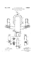
In Fig. 1 is shown a double-wave rectifier comprising an exhausted glass envelope 1 having a lower depending portion 2 constituting a container for mercury 3, two side arms 4 and 5 leading to anodes 6 and 7 respectively, and a condensing chamber 8 disposed directly above the mercury cathode. The depending portion 2 of the vessel, con stituting the mercury container, is provided, at its lower end, with a reentrant portion 10 to which is welded or sealed a metallic member 11 of cup-shape projecting upwardly in the-mercury for making electrical contact with the same.
An auxiliary electrode 12 is mounted adjacent to'the surface of the mercury 3 for maintaining an arc thereupon, in order to keep the mercury electrode in an electronemitting state during the entire operation of the device. The condensing chamber 8 may be provided with a cooling jacket 13 having an inlet 14 and an outlet 15 for circulating a cooling liquid therethrough.
The side arms 1 and 5 are preferably of tubular shape and have similarly shaped members 16 and 17, respectively, branching off therefrom. The anodes 6 and 7 are welded to the upper ends of the tubular members 16 and 17. In order to provide an efficient grid, the potential of which maybe controlled by a suitable lead-in wire, and which will reliably prevent the passage of the electrons between the grid and the walls of the vessel, we insert tubular members 18, which are preferably made of a woven wire fabric of a mercury resistant material, such as iron, into the side arms 4 and 5 respectively. The tabularshaped wire fabric is of a sulficientl; large ,We have found that the above construction permits a very effective control of the current flow between the cathode and the anodes. We ascribe the effectiveness of the arrangement partly to the fact that the mercury condenses between the walls of the vessel and the adjacent wire fabric, thus constituting a metallic layer entirely surrounding the path of the current adjacent to the grids. We also ascribe the effectiveness of this arrangement partly to the fact that, in places where the mercury might not form a continuous layer upon thewalls of the vessel, the tortuous path which must be traversed by an electron tending to slip towards the anode renders its passage very difficult and improbable. The wire fabric may be held in place by means of a suitable formation of the glass envelope, for instance, by means of indentations 19.
In Fig. 2 is shown a modification of our invention wherein the tubular-shape wire fabric 21 in inserted into the portion 16 of the vessel leading to the anode and in close engagement with the wall, and a grid 22 spans the tubular wire fabric to control the space-current flow.
In Fig. 3, a plane portion of wire fabric is so deformed as to constitute a spherical calotte 23 extending into a cylindrical portion 24 having the same diameter as the tubular member 16 of the glass vessel, the single member thus formed comprising both the grid and the enclosing metal member surrounding the current path.
In Fig. 4 is shown a modification of our invention wherein the tubular member 16 leading to the anode 7 is provided with an enlarged portion 25 into which the wire fabric 26 is so pressed as to come into close engagement with the glass walls surrounding the opening leading to the anode.
Although we have herein described several practical embodiments of our invention, We do not wish to be altogether limited to the particular details shown herewith, but seek to cover, in the appended claims, all such modifications as come within the scope and spirit of our invention.
We claim as our invention:
-1. In a space current device comprising a vessel of insulating'material, a tubular wire fabric portion engaging the inner walls of said vessel, means for providing, in effect, a grid spanning the entire passageway through said vessel within said tubular fabric portion, and an external electrical connections for said grid.
2. A gaseous current device comprising a vessel of insulating material, two main electrodes mounted in said vessel, means for providing a tubular wire fabric portion along the path of the current between said main electrodes, said tubular wire fabric portion being enclosed by, and in engagement with the walls of said vessel, and means for providing a grid spanning the entire section of the pat of the current within said tubular wire fabric portion. a
3. A vapor-current device comprisin a vessel, two main electrodes in said vessel, a tubular wire fabric portion within said vessel and engaging the walls of said vessel substantially entirely enclosing a portion of the path of current in said vessel, a grid extending across the current path within said tubular wire fabric portion, and an external electrical lead for said grid.
4. A vapor-current device comprising a vessel, two main electrodes in said vessel, a control electrode mounted between said electrodes comprising a Wire fabric extending across the path of the current and enga ing the inner walls of said vessel, said wire fa ric comprising also a portion entirely surrounding the path of the current flow and extending along the Walls of the vessel in a direction parallel to the path of the current-flow.
5. A. vapor-current device comprising a vessel, two main electrodes in said vessel, 9. control electrode mounted between said electrodes comprising a wire fabric extending across the path of the current and terminating in an integral tubular extension engaging the inner walls of the vessel, said extension entirely surrouding the path of the current and comprising walls parallel thereto.
6. A mercury arc device comprising a glass vessel, a mercury cathode in said vessel, an anode in spaced relation thereto and a control grid disposed between said cathode and said anode and comprising a wire fabric extending across a portion of said vessel, said wire fabric terminating in a tubular portion engaging at least a portion of the adjacent inner walls and extending a material distance in a direction parallel to, and entirely enclosing the path of the current flow between said cathode and said anode.
A gaseous current device comprising a vessel of insulating material, two main electrodesmounted in said vessel, means for providing a tubular Wire fabric portion along the path of the current between said main electrodes, said tubular wire fabric portion being enclosed by, and in engagement with, the walls of said vessel, and means for providing a grid spanning the entire section of the path of the current across said tubular wire fabric portion.
In testimony whereof, we have hereunto subscribed our names this 25th day of September, 1923.
VLADIMIR K. ZWORYKIN. DAYTON ULREY.
Priority Applications (1)
| Application Number | Priority Date | Filing Date | Title |
|---|---|---|---|
| US665487A US1856087A (en) | 1923-09-28 | 1923-09-28 | Mercury arc device with grid control |
Applications Claiming Priority (1)
| Application Number | Priority Date | Filing Date | Title |
|---|---|---|---|
| US665487A US1856087A (en) | 1923-09-28 | 1923-09-28 | Mercury arc device with grid control |
Publications (1)
| Publication Number | Publication Date |
|---|---|
| US1856087A true US1856087A (en) | 1932-05-03 |
Family
ID=24670308
Family Applications (1)
| Application Number | Title | Priority Date | Filing Date |
|---|---|---|---|
| US665487A Expired - Lifetime US1856087A (en) | 1923-09-28 | 1923-09-28 | Mercury arc device with grid control |
Country Status (1)
| Country | Link |
|---|---|
| US (1) | US1856087A (en) |
Cited By (1)
| Publication number | Priority date | Publication date | Assignee | Title |
|---|---|---|---|---|
| DE764007C (en) * | 1937-10-09 | 1954-05-10 | Siemens Schuckertwerke A G | Electric gas or vapor discharge vessel controlled in its work performance |
-
1923
- 1923-09-28 US US665487A patent/US1856087A/en not_active Expired - Lifetime
Cited By (1)
| Publication number | Priority date | Publication date | Assignee | Title |
|---|---|---|---|---|
| DE764007C (en) * | 1937-10-09 | 1954-05-10 | Siemens Schuckertwerke A G | Electric gas or vapor discharge vessel controlled in its work performance |
Similar Documents
| Publication | Publication Date | Title |
|---|---|---|
| US3154711A (en) | Electron beam focusing by means of contact differences of potential | |
| US1893887A (en) | Electron tube | |
| US1856087A (en) | Mercury arc device with grid control | |
| US2416661A (en) | Dispenser type cathode electric discharge device | |
| US2967260A (en) | Electron tube | |
| US2486134A (en) | Electric discharge device | |
| US2218331A (en) | Grid-controlled discharge tube | |
| US2020393A (en) | Gas discharge tube | |
| US2330849A (en) | Low pressure controlled discharge device | |
| US2748307A (en) | Magnetically forcused electron discharge device | |
| US2907905A (en) | Mercury vapor discharge device | |
| US1913427A (en) | Electric discharge device | |
| US2217436A (en) | Cathode for electron tubes | |
| US2770751A (en) | Construction of gas-filled tubes, particularly shielding | |
| US1749611A (en) | Method of rectifying alternating currents | |
| US2437146A (en) | Electrical discharge device employing a pool-type cathode | |
| US1815762A (en) | Electric discharge device | |
| US2022212A (en) | Low capacity thermionic tube | |
| US2082602A (en) | Thermionic cathode | |
| US2052103A (en) | Electric discharge tube | |
| US2747120A (en) | Single-ended thyratron discharge device | |
| US2724786A (en) | Grid control gaseous discharge rectifier tube | |
| US2559395A (en) | Controllable electron discharge tube having low tube losses | |
| US2078123A (en) | Electric discharge device | |
| US2248425A (en) | Rectifier tube |