US1856085A - Roller - Google Patents
Roller Download PDFInfo
- Publication number
- US1856085A US1856085A US301925A US30192528A US1856085A US 1856085 A US1856085 A US 1856085A US 301925 A US301925 A US 301925A US 30192528 A US30192528 A US 30192528A US 1856085 A US1856085 A US 1856085A
- Authority
- US
- United States
- Prior art keywords
- roller
- face layer
- collar
- stock
- resilient
- Prior art date
- Legal status (The legal status is an assumption and is not a legal conclusion. Google has not performed a legal analysis and makes no representation as to the accuracy of the status listed.)
- Expired - Lifetime
Links
- 239000000463 material Substances 0.000 description 36
- 238000000034 method Methods 0.000 description 4
- 239000003921 oil Substances 0.000 description 3
- 235000019198 oils Nutrition 0.000 description 3
- 239000000976 ink Substances 0.000 description 2
- 239000012858 resilient material Substances 0.000 description 2
- 238000009825 accumulation Methods 0.000 description 1
- 238000005266 casting Methods 0.000 description 1
- 238000010276 construction Methods 0.000 description 1
- 235000021388 linseed oil Nutrition 0.000 description 1
- 239000000944 linseed oil Substances 0.000 description 1
- 239000002184 metal Substances 0.000 description 1
- 238000012986 modification Methods 0.000 description 1
- 230000004048 modification Effects 0.000 description 1
- 230000001681 protective effect Effects 0.000 description 1
- 238000009877 rendering Methods 0.000 description 1
- 230000000452 restraining effect Effects 0.000 description 1
- 239000007787 solid Substances 0.000 description 1
- 238000007711 solidification Methods 0.000 description 1
- 230000008023 solidification Effects 0.000 description 1
- 239000000126 substance Substances 0.000 description 1
- 238000004073 vulcanization Methods 0.000 description 1
- 239000002023 wood Substances 0.000 description 1
Images
Classifications
-
- B—PERFORMING OPERATIONS; TRANSPORTING
- B41—PRINTING; LINING MACHINES; TYPEWRITERS; STAMPS
- B41N—PRINTING PLATES OR FOILS; MATERIALS FOR SURFACES USED IN PRINTING MACHINES FOR PRINTING, INKING, DAMPING, OR THE LIKE; PREPARING SUCH SURFACES FOR USE AND CONSERVING THEM
- B41N7/00—Shells for rollers of printing machines
- B41N7/06—Shells for rollers of printing machines for inking rollers
-
- B—PERFORMING OPERATIONS; TRANSPORTING
- B41—PRINTING; LINING MACHINES; TYPEWRITERS; STAMPS
- B41N—PRINTING PLATES OR FOILS; MATERIALS FOR SURFACES USED IN PRINTING MACHINES FOR PRINTING, INKING, DAMPING, OR THE LIKE; PREPARING SUCH SURFACES FOR USE AND CONSERVING THEM
- B41N2207/00—Location or type of the layers in shells for rollers of printing machines
- B41N2207/02—Top layers
Definitions
- This invention relates to a roller and has particular reference to a printers roller or a lithogra hic roller or an other roller or cylinder w ich embraces eit er a central core a of high resilency in combination .jgnith an outer face layer of tough exterior or a homogeneous material.
- this invention relates to a printers roller or lithographic roller espe- Ill cially adapted for use in resses in which the roller is subjected to wi e ranges of temperature and humidity and wherein-the re-- quirements are for a roller which will retain its resilience and toughness under all pracll tical conditions of use.
- the material facing adjacent the ends of the rolls becomes worn off and in many instances pieces of the facing are broken away or torn out rendering the end portions inefficient and unserviceable.
- the present invention contemplates building up the extreme outer ends of the roller with a tough resilient protecting homogeneous material similar in characteristics or of the same material as that of the composition formed on the stock or shaft.
- building up the outer ends of the roller is meant preferably casting a substantial collar on the stock to unite with the face layer and the resilient core, or with the homogeneous material if such. be employed, whereby to anchor and to protect the ends of these materials against checking, tearing, or damage from bumps.
- the surface of the outer ends of the roller, in excess of the working surface may be ground to provide a reduced diameter whereby dried ink and foreign matters are prevented from accumulating in a sufficient quantity to affect the accurac of the roller.
- this construction provi es that the entire inking or dampening surface of the rollor 1s supported by the resilient cushion and there is no restraining influence of a rigid nature.
- the built-up-ends of the roller be of the same diameter as that diameter of the working surface and may be of any desired consistency although it is referable to be hard.
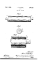
- Figure 1 is a front elevational view of a roller embodying the features of this'invention
- Fig. 2 is an end elevational view of the de vice shown in Fig. 1;
- Fig. 3 is an enlarged detail view of a portion of the roller shown in Fig. 1, partly in section.
- the roller comprises a central core portion 10 made of 75 a suitable resilient material, and a face layer 11 which surrounds and is prefer bly bonded to the resilient core 10.
- the out r face layer 11 is preferably composed of a homo eneous material which is relatively tougher t an the resilient core 10.
- the material from which the resilient core 10 is formed is preferably of vulcanized oil, such as linseed oil, and
- the face layer 11 of the roller may be made from the same general character of oil, although treated somewhat difierently to produce a tough and smooth outer face.
- a collar 14 is formed on the stock 12 and extends preferably the full distance between the end of the stock 12 and the ends of the outer face layer 11 and the resilient roller material 10. The collar 14 is preferably united with the materials of this assembly in order that the ends of the outer face layer 11 are anchored to the stock and the ends of the resilient roller material are protected against checking or tearing or other damage.
- a cylindrical collar of the same inside diameter as the outside diameter of the roller may be disposed around the outer periphery'of the face layer 11 to extend a substantial distance past the end of the stock 12.
- a material such as the material of the outer face layer 11, is then poured in the mold formed by the aforementioned cylinder as the roller is set on end whereby the uniting of the material thus poured with the materials of the roller is accomplished by means of vulcaniaation, or otherwise.
- vulcanization it 13 intended to mean the hardening or partialhardening or solidification of the oil, rubber, or analogous composition.
- the collar 14 is tough, although flexible, in order to form a protective cover ing over the comparatively soft resilient core and face layer.
- the outer surface thereof, together with the portion of the outer face roller 11, may be ground down to a size such that the external diameter of the collar is smaller than the external diameter of the face layer 11 and greater than the exbe understood 7 ternal diameter of the roller material or resilient core 10.
- the entire working surface of the face layer is uniformly cushioned by the resilient core 10. It will be particularly noted that the extreme outer ends of the resilient core 10 extend a short distance beyond the working surface of the face layer 11 in order to accomplish the aforementioned result.
- the ends of a homogeneous roller may be built up in the manner aforesaid.
- the homogeneous roller may be formed of a shaft or stock of metal, wood, or other desired material, either solid or hollow, having a cover consisting largely of vulcanized materials of any desired thickness.
- the collar 14 may be cast in such a manner that it will become a part of the roller surface and will provide either a hard or a soft strip at the ends of the roller.
- the diameter of the collar may be reduced to prevent the otherwise common accumulation of dried inks and other foreign substances thereat which latter affects the accuracy of the roller.
- a roller for the purpose set forth comprising a central core of high resilience havmg a face layer of tough exterior formed thereon, and a collar of tough flexible material ad'acent to and uniting with the ends of said ace layer and said core to anchor the ends of said face layer and to protect the ends of said central core, said collar being of a reduced diameter relative to the outside diameter of said face layer.
- a roller for the purpose set forth comprising a central core ofhigh resilience having a face layer of tough exterior formed thereon, and a collar of tough flexible material adjacent to and uniting with the ends of said face layer and said core to anchor the ends of said face layer and to protect the ends of said central core, said collar having an external diameter greater than the outer diameter of said central core and smaller than the outer diameter of said face layer.
- a roller for the purpose set forth comprising a rigid stock, a resilient roller material on said stock extending to within a spaced distanccof the ends thereof, a tough flexible face layer on said roller material, and a collar of tough flexible material on said stock at the ends of and uniting with said roller material and said face layer to anchor the ends of said face layer and to protect the ends of said roller material, said collar having a smaller external diameter than the external diameter of said face layer and a greater external diameter than the external diameter of said roller material, the'outer ends of said face layer being reduced to conform to the external diameter of said collar whereby the working surface of said face la er is uniformly cushioned.
Landscapes
- Rolls And Other Rotary Bodies (AREA)
Description
y 1932- WALTERS 1,856,085
ROLLER Filed Aug. 24, 1928 Wdiza/r Patented May 3, 1932 UNITED STATES PATENT OFFICE FRED G. WALTERS, 01! LONDON, ENGLAND, ASSIGNOB. BY MESNE ASSIGNMENTS, TO
IDEAL ROLLER ti IANUFAGTUIBING COMPANY, OF CHICAGO, ILLINOIS, A CORPORA- TION OF ILLINOIS ROLLER Application nled August 24, 1828. Serial No. 801,925.
This invention relates to a roller and has particular reference to a printers roller or a lithogra hic roller or an other roller or cylinder w ich embraces eit er a central core a of high resilency in combination .jgnith an outer face layer of tough exterior or a homogeneous material.
More particularly, this invention relates to a printers roller or lithographic roller espe- Ill cially adapted for use in resses in which the roller is subjected to wi e ranges of temperature and humidity and wherein-the re-- quirements are for a roller which will retain its resilience and toughness under all pracll tical conditions of use. Further, it has been the practice to bevel the ends of the roller material, whereinafter, the tough outer face layer of protecting material, in being applied to the bevelled portion of the roller material 8 falls away from the upper end thereof to leave the same inadequately protected. The material facing adjacent the ends of the rolls becomes worn off and in many instances pieces of the facing are broken away or torn out rendering the end portions inefficient and unserviceable.
The present invention contemplates building up the extreme outer ends of the roller with a tough resilient protecting homogeneous material similar in characteristics or of the same material as that of the composition formed on the stock or shaft. By building up the outer ends of the roller is meant preferably casting a substantial collar on the stock to unite with the face layer and the resilient core, or with the homogeneous material if such. be employed, whereby to anchor and to protect the ends of these materials against checking, tearing, or damage from bumps.
The surface of the outer ends of the roller, in excess of the working surface may be ground to provide a reduced diameter whereby dried ink and foreign matters are prevented from accumulating in a sufficient quantity to affect the accurac of the roller. Also, this construction provi es that the entire inking or dampening surface of the rollor 1s supported by the resilient cushion and there is no restraining influence of a rigid nature. However, it ma be desired that the built-up-ends of the roller be of the same diameter as that diameter of the working surface and may be of any desired consistency although it is referable to be hard.
Other objects and a vantages will hereinafter be more fully described and for a more complete understanding of the characteristic features of this invention reference mag now be had to the following description an accompanying drawings, wherein, for purposes of illustration, a roller composed of a central core of high resiliency covered with an outer face layer of tough resilient material is shown, in which:
Figure 1 is a front elevational view of a roller embodying the features of this'invention;
Fig. 2 is an end elevational view of the de vice shown in Fig. 1; and
Fig. 3 is an enlarged detail view of a portion of the roller shown in Fig. 1, partly in section.
Referring now to the drawings, the roller comprises a central core portion 10 made of 75 a suitable resilient material, and a face layer 11 which surrounds and is prefer bly bonded to the resilient core 10. The out r face layer 11 is preferably composed of a homo eneous material which is relatively tougher t an the resilient core 10. The material from which the resilient core 10 is formed is preferably of vulcanized oil, such as linseed oil, and
the face layer 11 of the roller may be made from the same general character of oil, although treated somewhat difierently to produce a tough and smooth outer face.
The combination of the aforementloned materials is deposited on a stock or shaft 12, which extends centrally through the aforementioned roller, a reduced portion thereof extending beyond the ends thereof to constitute the bearing member 13 therefor. The resilient roller material 10 and the outer face layer 11 terminate at a spaced distance from the end of the stock 12, this distance being from three-eighths of an inch to three inches long, or as may be desired. However, these dimensions are merely for the purpose of clearer description and it will that this invention is not to be limited to the same. A collar 14 is formed on the stock 12 and extends preferably the full distance between the end of the stock 12 and the ends of the outer face layer 11 and the resilient roller material 10. The collar 14 is preferably united with the materials of this assembly in order that the ends of the outer face layer 11 are anchored to the stock and the ends of the resilient roller material are protected against checking or tearing or other damage.
One of the methods of forming the roller material 10 and outer face layer '11 on the stock 12 and the apparatus therefor is more plainly shown and described in Patent No. 1,283,392 issued October 29. 1918, and assigned to the assignee of this application. However, it is to .be understood that various other methods, apparatus, and materials may be used in the making of the roller as embodied in this invention, and, therefore, inasmuch as such apparatus, methods and materials are old in the art, a more complete description is not believed to be necessary. However, one method of forming the collar portion 14 on the stock to unite with the materials of the roller will now be recited.
After the roller is assembled on the stock, a cylindrical collar of the same inside diameter as the outside diameter of the roller may be disposed around the outer periphery'of the face layer 11 to extend a substantial distance past the end of the stock 12. A material, such as the material of the outer face layer 11, is then poured in the mold formed by the aforementioned cylinder as the roller is set on end whereby the uniting of the material thus poured with the materials of the roller is accomplished by means of vulcaniaation, or otherwise. By vulcanization, it 13 intended to mean the hardening or partialhardening or solidification of the oil, rubber, or analogous composition. It is to be understood that the collar 14 is tough, although flexible, in order to form a protective cover ing over the comparatively soft resilient core and face layer.
After the collar is thus united with the ends of the roller materials, the outer surface thereof, together with the portion of the outer face roller 11, may be ground down to a size such that the external diameter of the collar is smaller than the external diameter of the face layer 11 and greater than the exbe understood 7 ternal diameter of the roller material or resilient core 10. By reducing the diameter of the end portions 15 of the face layer 11, the entire working surface of the face layer is uniformly cushioned by the resilient core 10. It will be particularly noted that the extreme outer ends of the resilient core 10 extend a short distance beyond the working surface of the face layer 11 in order to accomplish the aforementioned result.
As stated hereinbefore, the ends of a homogeneous roller may be built up in the manner aforesaid. The homogeneous roller may be formed of a shaft or stock of metal, wood, or other desired material, either solid or hollow, having a cover consisting largely of vulcanized materials of any desired thickness. The collar 14 may be cast in such a manner that it will become a part of the roller surface and will provide either a hard or a soft strip at the ends of the roller. However, in this instance, also, the diameter of the collar may be reduced to prevent the otherwise common accumulation of dried inks and other foreign substances thereat which latter affects the accuracy of the roller.
\Vhile but a single embodiment of this invention is herein shown and described, it is to be understood that various modifications thereof may be apparent. to those skilled in the art without departing from the spirit and scope'of this invention and therefore the same is'to be limited only by the scope ofthe appended claims and the prior art.
I claim:
1. A roller for the purpose set forth comprising a central core of high resilience havmg a face layer of tough exterior formed thereon, and a collar of tough flexible material ad'acent to and uniting with the ends of said ace layer and said core to anchor the ends of said face layer and to protect the ends of said central core, said collar being of a reduced diameter relative to the outside diameter of said face layer.
2. A roller for the purpose set forth comprising a central core ofhigh resilience having a face layer of tough exterior formed thereon, and a collar of tough flexible material adjacent to and uniting with the ends of said face layer and said core to anchor the ends of said face layer and to protect the ends of said central core, said collar having an external diameter greater than the outer diameter of said central core and smaller than the outer diameter of said face layer. I
3. A roller for the purpose set forth comprising a rigid stock, a resilient roller material on said stock extending to within a spaced distanccof the ends thereof, a tough flexible face layer on said roller material, and a collar of tough flexible material on said stock at the ends of and uniting with said roller material and said face layer to anchor the ends of said face layer and to protect the ends of said roller material, said collar having a smaller external diameter than the external diameter of said face layer and a greater external diameter than the external diameter of said roller material, the'outer ends of said face layer being reduced to conform to the external diameter of said collar whereby the working surface of said face la er is uniformly cushioned.
n witness whereof, I have hereunto subscribed my name.
FRED G. WALTERS.
Priority Applications (1)
| Application Number | Priority Date | Filing Date | Title |
|---|---|---|---|
| US301925A US1856085A (en) | 1928-08-24 | 1928-08-24 | Roller |
Applications Claiming Priority (1)
| Application Number | Priority Date | Filing Date | Title |
|---|---|---|---|
| US301925A US1856085A (en) | 1928-08-24 | 1928-08-24 | Roller |
Publications (1)
| Publication Number | Publication Date |
|---|---|
| US1856085A true US1856085A (en) | 1932-05-03 |
Family
ID=23165474
Family Applications (1)
| Application Number | Title | Priority Date | Filing Date |
|---|---|---|---|
| US301925A Expired - Lifetime US1856085A (en) | 1928-08-24 | 1928-08-24 | Roller |
Country Status (1)
| Country | Link |
|---|---|
| US (1) | US1856085A (en) |
Cited By (4)
| Publication number | Priority date | Publication date | Assignee | Title |
|---|---|---|---|---|
| US2600281A (en) * | 1948-09-07 | 1952-06-10 | Stickelber & Sons Inc | Sheeted dough transfer conveyer |
| US2625735A (en) * | 1948-12-07 | 1953-01-20 | Resistoflex Corp | End seal for printing rollers |
| US3722050A (en) * | 1970-11-16 | 1973-03-27 | Speed O Print Business Machine | Rollers |
| US4099312A (en) * | 1976-09-12 | 1978-07-11 | Ames Rubber Corporation | Elastomeric roll with sealed ends |
-
1928
- 1928-08-24 US US301925A patent/US1856085A/en not_active Expired - Lifetime
Cited By (4)
| Publication number | Priority date | Publication date | Assignee | Title |
|---|---|---|---|---|
| US2600281A (en) * | 1948-09-07 | 1952-06-10 | Stickelber & Sons Inc | Sheeted dough transfer conveyer |
| US2625735A (en) * | 1948-12-07 | 1953-01-20 | Resistoflex Corp | End seal for printing rollers |
| US3722050A (en) * | 1970-11-16 | 1973-03-27 | Speed O Print Business Machine | Rollers |
| US4099312A (en) * | 1976-09-12 | 1978-07-11 | Ames Rubber Corporation | Elastomeric roll with sealed ends |
Similar Documents
| Publication | Publication Date | Title |
|---|---|---|
| US5059041A (en) | Electrical insulating bearing | |
| US1856085A (en) | Roller | |
| US3522643A (en) | Resilient table roller | |
| US2119491A (en) | Roller | |
| US6053489A (en) | Elastic bearing structures particularly for wheel suspensions of motor vehicles | |
| US4299283A (en) | Strip structure for well screen | |
| US2464082A (en) | Method of casting printing rollers | |
| US2032484A (en) | Segmental grinding wheel | |
| US3682094A (en) | Clad metal member | |
| US2178421A (en) | Rubber roll | |
| US1307800A (en) | Assxotoss to | |
| US1669942A (en) | Roller | |
| US1603880A (en) | Bowling pin | |
| US2746637A (en) | Abrasion resistant liner | |
| US2094569A (en) | Equalizer spring cap and seat | |
| US1926312A (en) | Printer's roller | |
| SE465582B (en) | STONE ROLL FOR MACHINERY FOR MAKING PAPER, CARTON AND SIMILAR AND METHOD FOR MAKING A STONE ROLL | |
| US1648413A (en) | Railway-car-wheel construction | |
| US1498180A (en) | Roller | |
| US1853258A (en) | Printer's blanket | |
| US1588008A (en) | Method of forming cushion tires | |
| US1404209A (en) | Roller | |
| US2516693A (en) | Abrasive wheel | |
| US2582516A (en) | Railway car axle | |
| US3195853A (en) | Chill mat |