US1856081A - Cylinder paper machine - Google Patents
Cylinder paper machine Download PDFInfo
- Publication number
- US1856081A US1856081A US184474A US18447427A US1856081A US 1856081 A US1856081 A US 1856081A US 184474 A US184474 A US 184474A US 18447427 A US18447427 A US 18447427A US 1856081 A US1856081 A US 1856081A
- Authority
- US
- United States
- Prior art keywords
- cylinder
- screen
- stock
- flow
- paper
- Prior art date
- Legal status (The legal status is an assumption and is not a legal conclusion. Google has not performed a legal analysis and makes no representation as to the accuracy of the status listed.)
- Expired - Lifetime
Links
- 241000239290 Araneae Species 0.000 description 5
- 238000009950 felting Methods 0.000 description 4
- 239000000835 fiber Substances 0.000 description 4
- 238000010276 construction Methods 0.000 description 3
- 230000000694 effects Effects 0.000 description 3
- 230000001105 regulatory effect Effects 0.000 description 3
- 241001052209 Cylinder Species 0.000 description 2
- XEEYBQQBJWHFJM-UHFFFAOYSA-N Iron Chemical compound [Fe] XEEYBQQBJWHFJM-UHFFFAOYSA-N 0.000 description 2
- 230000001427 coherent effect Effects 0.000 description 2
- 244000221110 common millet Species 0.000 description 2
- 238000004519 manufacturing process Methods 0.000 description 2
- 239000002351 wastewater Substances 0.000 description 2
- XLYOFNOQVPJJNP-UHFFFAOYSA-N water Substances O XLYOFNOQVPJJNP-UHFFFAOYSA-N 0.000 description 2
- 238000013019 agitation Methods 0.000 description 1
- 239000012530 fluid Substances 0.000 description 1
- 238000009434 installation Methods 0.000 description 1
- 229910052742 iron Inorganic materials 0.000 description 1
- 230000003340 mental effect Effects 0.000 description 1
- 239000002184 metal Substances 0.000 description 1
- 229910052751 metal Inorganic materials 0.000 description 1
- 238000000034 method Methods 0.000 description 1
- NJPPVKZQTLUDBO-UHFFFAOYSA-N novaluron Chemical compound C1=C(Cl)C(OC(F)(F)C(OC(F)(F)F)F)=CC=C1NC(=O)NC(=O)C1=C(F)C=CC=C1F NJPPVKZQTLUDBO-UHFFFAOYSA-N 0.000 description 1
- 238000005192 partition Methods 0.000 description 1
- 229920000136 polysorbate Polymers 0.000 description 1
- 238000000926 separation method Methods 0.000 description 1
Images


Classifications
-
- D—TEXTILES; PAPER
- D21—PAPER-MAKING; PRODUCTION OF CELLULOSE
- D21F—PAPER-MAKING MACHINES; METHODS OF PRODUCING PAPER THEREON
- D21F9/00—Complete machines for making continuous webs of paper
- D21F9/04—Complete machines for making continuous webs of paper of the cylinder type
Definitions
- Our invention relates'to improvements in paper-making machines of the cylinder type in which the paper is formed upon a revolving cylindrical screen.
- chines of the cylinder type have generally been of the immersed or wet vat type 1n which the paper stock fills the vat suffic ently to immerse the major part of the cyllnder, leaving exposed only a relatively small zone at the top of the cylinder before the final draining of the paper is effected prior to its removal from under the couch roll.
- the present invention contemplates in its preferred aspects, a machine of a somewhat m different type in which the paper stock 1s directed upon the upper surface of the cylinder only, the remainder or lower part of the cylinder being preferably not subjected to the flow of stock.
- a machine of this type 29 may be conveniently designated as a cylinder machine of the dry vat type.
- the objects of the invention are to provide, in general, a cylinder paper machine of the dry vat type; to provide a machine in which the paper stock, while on the wire, is sufficiently agitated relative to the screen so as to secure a more perfect felting" action of the fibers of the stock; to provide a construction which will facilitate the production of a paperweb of great uniformity in thickness, not only in reference to points longitudinally of the web, but also with reference to difl'erent points across the web; to provide a machine of the class described in which the regulation of flow of stock to the screen may be effected rapidly, conveniently, and accurately; to provide a machine of the class described which is well adaptedto cooperate with others of a series. of such ma chines; to provide a construction which is relatively simple in design and economical to manufacture, and in general, to provide an eflicient and improved machine of the character referred to.
- FIG. 3 is a section taken on the line 3-3 of Fig. 1.
- Fig. 4 is a section taken on the line 44 of Fig. 2. i
- Fig. 5 is a fragmentary elevation of a portion of the machine showing the vibratory mechanism
- Fig. 6 is a section taken on the line 6--6 of Flg. 3.
- the numeral 10 represents the vat of the machine which, however, in this case serves principally to support the cylinder.
- the said vat 10, as well illustrated in Figs. 3 and 4; comprises a pair of rigid upstanding end frames 11 and 12 connected by longitudinally extending walls 13, 14., with a bottom or base wall 15.
- the base wall 15 is provided with a discharge opening 16 leading into a pipe 17 which takes care of the waste water from the cylinder.
- brackets 18 and 19 which support the pedestal bearings 20 and 21 in which the shaft 22 of the cylinder rotates.
- Said shaft 22 is driven by any usual source of power, not shown, it being understood that the speed of the shaft 22 may be regulated in accordance with the operating conditions.
- To the shaft 22 there are secured end spiders 23 and 24 and an intermediate spider 25, which spiders are of such diameter as to furnish rotating supports for av cone-shaped diaphragm member 26.
- a ring part 27 having flanges 28 and 29 fitting the peri hery of the spider 23 and secured thereto.
- a slip ring 30 may be fitted over the joint so as to maintain the same in well fitting condition, evcn'though there is a slight longitudinal movement of the cylin der causing a separation of the ends of the flanges 28 and 29.
- a somewhat similar ring element 31 secured to .the periphery of the spider 24 and havin a radially extending, annular flan e 32 whlch is connected to the ring element y means of webs such as 32.
- the outer face of the flange 32 is formed with a c lindric outwardly projecting flange 33. rotates against the end of the flange 34, also similar in sha e and formed as an integral part of the en frame 12.
- a similar seal ng ring 35 is employed to make more positive the joint betweenthe ends of said flanges 33 and
- the screen proper 36 which'may be of the type usually employed in standard cylinder machines,-is of a diameter considerably in excess ofthe diameter of the lar e end of the cone member 26, and at one an is supported a radial flange 32 of the ring element 31, and at the other end by a similar radial flange 37 formed as an extension of the ring element 28.
- annular rib elements 38 fitting within the screen and suitably spaced longitudinally thereof.
- each of the compartments 40 is provided with a set of apertures or ports, 42.
- the flange 33 on the right hand end of the cylinder is of such inside diameter that the ringelement- 31 and its flange 32 may be machined off to form in eifect a valve face having the openings 42 extending therethrough as valve ports.
- the end frame 12 On theainside face of the end frame 12,
- a suction chamber 43 communieating through an opening 44 with a suction line 45.
- the suction line 45 is connected to a
- the vacuum chamber 43 as shown best in Figs. 1 and 6, isa segmental annulus of the proper dimensions and location to register with several of compartments simultaneously.
- the inside face of. the end of the vacuum chamber 43 is machined 0a so as to form a running seal joint against the valve face through which extend the ports 42 of the cylinder. It will be observed that the vacuum chamber 43 is positioned at the-top of the cylinder which is the he flange.
- the distributor roll 54 is so located in the flow box50 that the stock in passing through the throat or discharge opening 56 of the flow box, is compelled in large measure to pass through the perforations in the drum.
- the depth of stock in the flow box is maintained at approximatel the level of the top of the distributor r0 1 or drum 54.
- the throat 56 is capable of being regulated by a vertically s'lidable gate member 57, the lower end of which is madewith an enlargement 58 extending all the way across the lower edge of the gate 57.
- the lower corner of the enlargement 58 is-suitably machined and fitted with a correspondingly machined cap strap 59 ,50 as to provide aearing for a swingingl'y'mounted regulator plate 60 inclined downwardly from the pivot, as shown.
- Near the lower edge of the regulator plate 60 thereis secured a series of brackets or pivot blocks 61, each of which by means of a 1 5 pin 62is pivotally connected tothe lower. end of an adjustment rod 63, which "adjustment rod 63 extends through the enlarged lower end 64 of a hanger 65 and is capabl rnent of various portions thereof.
- the flow of stock it extends through the orifice h horizontally extending shaft 68.
- the shaft 68 is eccentrically mounted in cylindrical blocks 69, journaled in suitable bearin at 'each side of the machine and to one o the blocks 69 there is keyed a segmental worm ear 70, with which cooperates an axially Jared worm element 71 which is mounted on a vertical shaft 72 capable of being rotated in its bearings by a hand wheel 7 3.
- y means of the hand wheel 73, the eccentrically 33 mounted shaft may be swung around so as to elevate or depress the entire series of ad yiusting rods 63 simultaneously.
- the plate 60 is suiiiciently flexible to permit of such individual adjustlhc bottom wall 74 of the forward ortion of the flow box is preferably made 0 metal and is extended in advance of the distributor roll a substantial distance, said extension 75 being machined as shown in Fig. 4, to consti- 39 tute a bearing for the vibratory bottom late 76.
- Said bottom shaker plate 76 is he d in -;close fitting engagement with the bottom plate 75 cf the flow box by means of an under-cut bar 7 7 secured to the lower face of the shaker and cooperating with the reduced front edge'78 of the bottom plate 75.
- the top of the shaker late 76 and the under side of the regulator p ate 60 constitute, in effect, a tapered flow conduit extending all the way the dischar e opening between the outer ends of said plates determining the amountof stock which is discharged on to the screen.
- Said openin may be regulated on to the screen, as it passes out of the opening between the oritice plates 60 and 76, is guided by a thin sheet rubber apron 79 whlch is secured to the upper surface of the shaker plate 76 and and a short distance along the screen upon which it rests.
- deckle stra s Although we have not illustrated anything f in the nature of deckle stra s, it may be desirable, in certain cases w are a proper 55 edge for the sheet is desired, to employ fixed or movable deckle straps or belts which can be fitted in any convenient manner so that the flow of stock does not spread out sidewise towards the edges of the cylinder.
- a shaking movement is imparted to the apron 79 which, as before stated, is secured to and consequently moves with shaker plate 76.
- Said shaker mechanism is shown est in Figs. 1, 2 and 5. Referring to said as previously describe resents a column or standard, the u per en of which carries a bracket 81 on w ich there is mounted an electric motor 82. Said electric motor 82 runs continuously and through a reducin mechanism 83 drives a shaft 84 at relative y low speed.
- belt 88 and the resultin speed of shaft may be changed by a shi t b ock 89 threadedly connected to a screw shaft 90.
- Said vscrew s aft 90 is mounted in suitable bearings, and when adjustment is desired, is actuated or rotated by a crank handle 91 which operates the shaft 90- through a pair of cooperating spur gears 92 and 93.
- the shaker plate 76 may be given there is keyed a vibratory movement in a longitudinal dieflects t as desired agitation of the stock as it flows upon the surface of the cylindrical screen.
- the paper web is, of course, formed upon that portion of the screen which extends be tween the apron 79 and the couch roll 99, which may be of the usual form. It will be understood also, that the web is picked up b a felt which extends aroundthe couch roll 99 and passes between the couch roll and the first press roll 101. Subsequently the web is handled and dried in the usual manner, either sin ly or it may be combined with the webs of ot er similar machines to form paper pr board of greater thickness.
- flow m means for dlrectmg u on an upper portion of the screen a define flow of pa r stock in a stream substantially tangential to the periphery of the cylinder, web removing means, and means for rotating the cylinder in a direction to carry the flow of, stock upwardly on the cylinder and towards the web removing means.
- a cylinder aper machine of the dry vat type the com ination of a cylindrical forming screen, means for rotating said screen on a horizontal axis, flow means for directing a defined stream of paper stock upon said screen in a direction substantially tangential to the periphery of the cylinder, and web removing means spaced from said flow means.
- a cylindrical 30 forming screen In a cylinder paper machine of the dry vat type, the combination of a cylindrical 30 forming screen, means for rotating said screen on a horizontal axis, flow means for directing upon sald screen in a direction substantially tangential to the periphery of the cylinder .13 and in the direction of rotation of said cylinder, Web removing means spaced from said flow means, and means for applying suction to the inner surface of said screen located between the flow means and the web removl0 ing means.
- a cylindrical forming screen In a cylinder paper machine of the dry .vat type, the combination of a cylindrical forming screen, means for rotating said screen on a horizontal axis, flow means for a defined stream of paper stock upon sa1d screen in a direction substantially tangential to the periphery of the cylinder and in the direction of rotation of said cylinder, web removing means s need-from said so flow means, and means for e eeting relatlve movement ofsaid screen and flow means to acilitate felting of the fibers.
- acylindrical I forming screen In a cylinder paper machine of the dry vat type, the combination of acylindrical I forming screen, means for rotating said screen on a horizontal axis, flow means for directing a defined stream of paper stock upon said screen in a direction substantially tangential to the periphery of the cylinder and in the direction of rotation of said cylinder, web removingimeans spaced from said flow means, means for efiecting relative -movement of said, screen and flow means to facilitate felting of the fibers, said last mentioned means comprising an apron for supcglinder' and in the direction of rotation of sal a defined stream of paper stock porting the flow of stock, .and means for reciprocating said apron.
- a cylinder aper machine of the dry vat type the com ination of a cylindrical, forming screen, means for rotating saidsereen on a horizontal axis, means for directmg a relatively shallow, flowing stream of paper stock substantially tangentially onto a portion of said cylindrical screen, means for draining part of the water from said stream so as to form a: layer of coherent paper stock on the cylinder, and means for removing said layer from said cylinder.
- a cylinder paper machine of the dry vat type the com ination of a cylindrical forming screen, means for rotating said screen on a horizontal axis, means -directing arelatively shallow, flowing stream of paper stock substantially tan entially onto a portion of said cylindrica screen means or adjusting the depth of said stream, means for draining part of the ,water from said stream so as to form a layer of coherent paper stock on the cylinder, and means for removing said layer from said cylinder.
- a cylindrical forming screen In a cylinder paper machine of the dry vat type, the combination of a cylindrical forming screen, means for rotating said screen on a horizontal axis, flow means for directing a defined stream of paper stock upon said screen in a direction substantially tangential to the periphery of the cylinder and "in the direction of rotation of said cyl inder,.web removing means spaced from said flow means, means locatedbetween said flow means and said web removing means for ap plying suction to the inner surface of saidscreen, and means for applying fluid pressure to the inside of a part of said screen to facilitate removal of said web by said web removing means.
Landscapes
- Paper (AREA)
Description
y 1932- E. A. PETERSON E'l AL ,856,081
CYLINDER PAPER MACHINE 5 Sheets-Sheet 1 Filed April 18 1927 I .jferm 2% Jam W, M 1 4 M y 1932- E. A. PETERSON ET AL 1,856,081
CYLINDER PAPER MACHINE,
Filed April 18. 1927 5 Sheets-Sheet 2 s2, 72v 5 I47 fzg m May 3, 1932. E. A. PETERSON ET AL CYLINDER PAPER MACHINE Filed April 18, 1927 5 Sheets-Sheet 3 May 3, 1932.
E. A. PETERSON ET AL CYLINDER PAPER MACHINE Filed April 18. 1927 5 Sheets-$heet 4 R Q Q nu May 3,- 1932. E. A. PETERSON ET AL CYLINDER PAPER MACHINE Filed April 18,
1927 5 Sheets-Sheet 5 Patented May 3, 1932 UNITED STATES PATENT OFFICE EMIL A. PETERSON AND WILLIAM JAMES MCGINNI S, OF APPLETON,, WISCONSIN, AS- SIGNORS TO VALLEY IRON WORKS COMPANY, 01 APPLETON, WISCONSIN, A CQB- POBATION OI WISCONSIN CYLINDER PAPER MACHINE Application filed April 18, 1927. Serial No. 184,474.
Our invention relates'to improvements in paper-making machines of the cylinder type in which the paper is formed upon a revolving cylindrical screen. Heretofore, ma-
chines of the cylinder type have generally been of the immersed or wet vat type 1n which the paper stock fills the vat suffic ently to immerse the major part of the cyllnder, leaving exposed only a relatively small zone at the top of the cylinder before the final draining of the paper is effected prior to its removal from under the couch roll.
The present invention contemplates in its preferred aspects, a machine of a somewhat m different type in which the paper stock 1s directed upon the upper surface of the cylinder only, the remainder or lower part of the cylinder being preferably not subjected to the flow of stock. A machine of this type 29 may be conveniently designated as a cylinder machine of the dry vat type.
Hence, the objects of the invention are to provide, in general, a cylinder paper machine of the dry vat type; to provide a machine in which the paper stock, while on the wire, is sufficiently agitated relative to the screen so as to secure a more perfect felting" action of the fibers of the stock; to provide a construction which will facilitate the production of a paperweb of great uniformity in thickness, not only in reference to points longitudinally of the web, but also with reference to difl'erent points across the web; to provide a machine of the class described in which the regulation of flow of stock to the screen may be effected rapidly, conveniently, and accurately; to provide a machine of the class described which is well adaptedto cooperate with others of a series. of such ma chines; to provide a construction which is relatively simple in design and economical to manufacture, and in general, to provide an eflicient and improved machine of the character referred to.
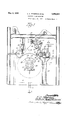
Referring to the drawings which illustrate Fig. 3 is a section taken on the line 3-3 of Fig. 1.
Fig. 4 is a section taken on the line 44 of Fig. 2. i
Fig. 5 is a fragmentary elevation of a portion of the machine showing the vibratory mechanism, and
Fig. 6 is a section taken on the line 6--6 of Flg. 3.
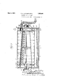
Referring to-the drawings, the numeral 10 represents the vat of the machine which, however, in this case serves principally to support the cylinder. The said vat 10, as well illustrated in Figs. 3 and 4;, comprises a pair of rigid upstanding end frames 11 and 12 connected by longitudinally extending walls 13, 14., with a bottom or base wall 15. The base wall 15 is provided with a discharge opening 16 leading into a pipe 17 which takes care of the waste water from the cylinder.
On' the outside faces of the end frames 11 and 12 there are suitably secured brackets 18 and 19 which support the pedestal bearings 20 and 21 in which the shaft 22 of the cylinder rotates. Said shaft 22 is driven by any usual source of power, not shown, it being understood that the speed of the shaft 22 may be regulated in accordance with the operating conditions. To the shaft 22 there are secured end spiders 23 and 24 and an intermediate spider 25, which spiders are of such diameter as to furnish rotating supports for av cone-shaped diaphragm member 26. To facilitate such connection, at thelarge end of the cone there is fitted a ring part 27 having flanges 28 and 29 fitting the peri hery of the spider 23 and secured thereto. 11 the outer face of the ring element 27 there is a cylindric outwardly projecting flange 28 of the same diameter as, and fitting against a similar stationary flange 29 on the inside face of, the end frame 11, the slip joint between the ends of said flanges forming in effect a seal between the rotating and stationary elenients. If desired, a slip ring 30 may be fitted over the joint so as to maintain the same in well fitting condition, evcn'though there is a slight longitudinal movement of the cylin der causing a separation of the ends of the flanges 28 and 29. v
At the smaller end of the cone, there is fitted a somewhat similar ring element 31 secured to .the periphery of the spider 24 and havin a radially extending, annular flan e 32 whlch is connected to the ring element y means of webs such as 32. The outer face of the flange 32 is formed with a c lindric outwardly projecting flange 33. rotates against the end of the flange 34, also similar in sha e and formed as an integral part of the en frame 12. A similar seal ng ring 35 is employed to make more positive the joint betweenthe ends of said flanges 33 and The screen proper 36 which'may be of the type usually employed in standard cylinder machines,-is of a diameter considerably in excess ofthe diameter of the lar e end of the cone member 26, and at one an is supported a radial flange 32 of the ring element 31, and at the other end by a similar radial flange 37 formed as an extension of the ring element 28. In order to insure that the screen 36 will maintain its truly cylindrical shape, it is preferred to support the same at intermediate points by annular rib elements 38, fitting within the screen and suitably spaced longitudinally thereof. Referrin now to Figs. 4 and 6, it will be seen that t e space between the inner cone and the outer cylindrical screen 36 of the cylinder is divided longitudinall into compartments 40by a seriesof radia and longitudinally extending partitions 39. Each of these compartments is closed at its small end by a flange 41 secured to the flange 37 and at the large end each of the compartments is similarly partially closed by radial flange 32. However, at a point immediately above the small end of the cone 26, each of the compartments 40 is provided with a set of apertures or ports, 42.
It will be observed that the flange 33 on the right hand end of the cylinder (see Fig. 3) is of such inside diameter that the ringelement- 31 and its flange 32 may be machined off to form in eifect a valve face having the openings 42 extending therethrough as valve ports. On theainside face of the end frame 12,
there is cast a suction chamber 43 communieating through an opening 44 with a suction line 45. The suction line 45 is connected to a uitable vacuum pump installation capable o maintaining a rarefication to suit the particular requirements. The vacuum chamber 43, as shown best in Figs. 1 and 6, isa segmental annulus of the proper dimensions and location to register with several of compartments simultaneously. The inside face of. the end of the vacuum chamber 43 is machined 0a so as to form a running seal joint against the valve face through which extend the ports 42 of the cylinder. It will be observed that the vacuum chamber 43 is positioned at the-top of the cylinder which is the he flange. 33 I delivery end of the flow box 50 there is a of adjustment therein by means of hand opplace where the paper web is being formed. .At one end of the vacuum chamber 43 there is formed an inte al flange 46 which is faced off level with t e inner end of the suction chamber so as to fit the valve face and thereby prevent loss of vacuum due to the fact that the compartments are wider than the thickness of the end wall 47 of the vacuum chamber. At theopposite end of the vacuum chamber there is a similar flange which, however, is made with a port 48 communieating with a pi e 49 extending through and frame 12 and w ich may be su plied with air at a pressure slightly excee in that of the atmosphere. This port 48 an pipe 49 are for the purpose of freeing the web from the screen in the event that there is any tendency of same to stick thereto.
Having described the cylinder construction and arrangements for applying suction,
there will now be described another important phase of the invention, which resides in the method and means for conducting the paper stock uniformly to the wire or screen. The arrangement which is preferred for this purpose is what may be termed ,the kinetic type. So far as known, this type of stock flow has never been employed successfully in connection with paper cylinder machines, although it is' largely used on paper-making machines of the Fourdrinier type. Referring to Fig. 4, 50 is the head box provided with suitable baffles 51 and 52 and receiving stock through the pipe 53. In the front or hollow, perforated distributor I roll 54 mounted upon a horizontal shaft 55, which may be driven at suitable speed by any usual source I of power. The distributor roll 54is so located in the flow box50 that the stock in passing through the throat or discharge opening 56 of the flow box, is compelled in large measure to pass through the perforations in the drum. Preferably, the depth of stock in the flow box is maintained at approximatel the level of the top of the distributor r0 1 or drum 54.
The throat 56 is capable of being regulated by a vertically s'lidable gate member 57, the lower end of which is madewith an enlargement 58 extending all the way across the lower edge of the gate 57. The lower corner of the enlargement 58 is-suitably machined and fitted with a correspondingly machined cap strap 59 ,50 as to provide aearing for a swingingl'y'mounted regulator plate 60 inclined downwardly from the pivot, as shown. Near the lower edge of the regulator plate 60 thereis secured a series of brackets or pivot blocks 61, each of which by means of a 1 5 pin 62is pivotally connected tothe lower. end of an adjustment rod 63, which "adjustment rod 63 extends through the enlarged lower end 64 of a hanger 65 and is capabl rnent of various portions thereof.
across the machine,
' The flow of stock it extends through the orifice h horizontally extending shaft 68. The shaft 68 is eccentrically mounted in cylindrical blocks 69, journaled in suitable bearin at 'each side of the machine and to one o the blocks 69 there is keyed a segmental worm ear 70, with which cooperates an axially Jared worm element 71 which is mounted on a vertical shaft 72 capable of being rotated in its bearings by a hand wheel 7 3. y means of the hand wheel 73, the eccentrically 33 mounted shaft may be swung around so as to elevate or depress the entire series of ad yiusting rods 63 simultaneously. Whereas, if it is desired to adjust any portion of the plate independently of other portions, such to ad'ustment may be effected by means of the in ividual adjusting nuts 66 and 67. It will be understood that the plate 60 is suiiiciently flexible to permit of such individual adjustlhc bottom wall 74 of the forward ortion of the flow box is preferably made 0 metal and is extended in advance of the distributor roll a substantial distance, said extension 75 being machined as shown in Fig. 4, to consti- 39 tute a bearing for the vibratory bottom late 76. Said bottom shaker plate 76 is he d in -;close fitting engagement with the bottom plate 75 cf the flow box by means of an under-cut bar 7 7 secured to the lower face of the shaker and cooperating with the reduced front edge'78 of the bottom plate 75. The top of the shaker late 76 and the under side of the regulator p ate 60 constitute, in effect, a tapered flow conduit extending all the way the dischar e opening between the outer ends of said plates determining the amountof stock which is discharged on to the screen. Said openin may be regulated on to the screen, as it passes out of the opening between the oritice plates 60 and 76, is guided by a thin sheet rubber apron 79 whlch is secured to the upper surface of the shaker plate 76 and and a short distance along the screen upon which it rests.
Although we have not illustrated anything f in the nature of deckle stra s, it may be desirable, in certain cases w are a proper 55 edge for the sheet is desired, to employ fixed or movable deckle straps or belts which can be fitted in any convenient manner so that the flow of stock does not spread out sidewise towards the edges of the cylinder.
In order to obtain a better felting of the stock fibers, a shaking movement is imparted to the apron 79 which, as before stated, is secured to and consequently moves with shaker plate 76. Said shaker mechanism is shown est in Figs. 1, 2 and 5. Referring to said as previously describe resents a column or standard, the u per en of which carries a bracket 81 on w ich there is mounted an electric motor 82. Said electric motor 82 runs continuously and through a reducin mechanism 83 drives a shaft 84 at relative y low speed. Spaced from the shaft 84, there is also mounted in suitable bearin s, a second horizontal shaft 85and on sai shafts 84 and 85 there are keyed a pair of coned alleys 86 and 87 connected by a belt 88. 'l he position of the figures, re
On one end of the shaft 85 an eccentric 94 coo crating with an eccentric strap 95 on the en of a pitman 96. The pitman 96 is ivotally connected by means of a pin 97 to ,ugs 98 secured on the end of the shaker plate 76. 7 Bythe above described mechanism, the shaker plate 76 may be given there is keyed a vibratory movement in a longitudinal dieflects t as desired agitation of the stock as it flows upon the surface of the cylindrical screen.
The paper web is, of course, formed upon that portion of the screen which extends be tween the apron 79 and the couch roll 99, which may be of the usual form. It will be understood also, that the web is picked up b a felt which extends aroundthe couch roll 99 and passes between the couch roll and the first press roll 101. Subsequently the web is handled and dried in the usual manner, either sin ly or it may be combined with the webs of ot er similar machines to form paper pr board of greater thickness.
It will be understood that in the operation of the machine,by reason of the compartment arrangement of the cylinder, and the se mental shape of the suction chamber, on y that portion .of the screen which is at that time carrying the stock or the. partially ormed web is subjected to suction, so that it is not necessary to employ an inordinate size of pump for producing the necessary suction effect. Obviously, since the cylinder surface is open to the atmosphere, except in the zone where it carries the web, the waste water which finds it way through the screen into the various compartments 40, will flow out of the compartments through the screen during the movement of the. various compartments below the horizontal plane extending through the axis of the cyllnder. As pre- 45 directing binationof a cylindrical forming screen, flow m means for dlrectmg u on an upper portion of the screen a define flow of pa r stock in a stream substantially tangential to the periphery of the cylinder, web removing means, and means for rotating the cylinder in a direction to carry the flow of, stock upwardly on the cylinder and towards the web removing means.
2. In a cylinder aper machine of the dry vat type, the com ination of a cylindrical forming screen, means for rotating said screen on a horizontal axis, flow means for directing a defined stream of paper stock upon said screen in a direction substantially tangential to the periphery of the cylinder, and web removing means spaced from said flow means.
3. In a cylinder paper machine of the dry vat type, the combination ofa cylindrical 30 forming screen, means for rotating said screen on a horizontal axis, flow means for directing upon sald screen in a direction substantially tangential to the periphery of the cylinder .13 and in the direction of rotation of said cylinder, Web removing means spaced from said flow means, and means for applying suction to the inner surface of said screen located between the flow means and the web removl0 ing means.
4. In a cylinder paper machine of the dry .vat type, the combination of a cylindrical forming screen, means for rotating said screen on a horizontal axis, flow means for a defined stream of paper stock upon sa1d screen in a direction substantially tangential to the periphery of the cylinder and in the direction of rotation of said cylinder, web removing means s need-from said so flow means, and means for e eeting relatlve movement ofsaid screen and flow means to acilitate felting of the fibers.
5. In a cylinder paper machine of the dry vat type, the combination of acylindrical I forming screen, means for rotating said screen on a horizontal axis, flow means for directing a defined stream of paper stock upon said screen in a direction substantially tangential to the periphery of the cylinder and in the direction of rotation of said cylinder, web removingimeans spaced from said flow means, means for efiecting relative -movement of said, screen and flow means to facilitate felting of the fibers, said last mentioned means comprising an apron for supcglinder' and in the direction of rotation of sal a defined stream of paper stock porting the flow of stock, .and means for reciprocating said apron.
6. In a cylinder aper machine of the dry vat type, the com ination of a cylindrical, forming screen, means for rotating saidsereen on a horizontal axis, means for directmg a relatively shallow, flowing stream of paper stock substantially tangentially onto a portion of said cylindrical screen, means for draining part of the water from said stream so as to form a: layer of coherent paper stock on the cylinder, and means for removing said layer from said cylinder.
7. In a cylinder paper machine of the dry vat type, the com ination of a cylindrical forming screen, means for rotating said screen on a horizontal axis, means -directing arelatively shallow, flowing stream of paper stock substantially tan entially onto a portion of said cylindrica screen means or adjusting the depth of said stream, means for draining part of the ,water from said stream so as to form a layer of coherent paper stock on the cylinder, and means for removing said layer from said cylinder.
8. In a cylinder paper machine of the dry vat type, the combination of a cylindrical forming screen, means for rotating said screen on a horizontal axis, flow means for directing a defined stream of paper stock upon said screen in a direction substantially tangential to the periphery of the cylinder and "in the direction of rotation of said cyl inder,.web removing means spaced from said flow means, means locatedbetween said flow means and said web removing means for ap plying suction to the inner surface of saidscreen, and means for applying fluid pressure to the inside of a part of said screen to facilitate removal of said web by said web removing means.
E. A. PETERSON. WM. J. MCGINNIS.
Priority Applications (1)
| Application Number | Priority Date | Filing Date | Title |
|---|---|---|---|
| US184474A US1856081A (en) | 1927-04-18 | 1927-04-18 | Cylinder paper machine |
Applications Claiming Priority (1)
| Application Number | Priority Date | Filing Date | Title |
|---|---|---|---|
| US184474A US1856081A (en) | 1927-04-18 | 1927-04-18 | Cylinder paper machine |
Publications (1)
| Publication Number | Publication Date |
|---|---|
| US1856081A true US1856081A (en) | 1932-05-03 |
Family
ID=22677022
Family Applications (1)
| Application Number | Title | Priority Date | Filing Date |
|---|---|---|---|
| US184474A Expired - Lifetime US1856081A (en) | 1927-04-18 | 1927-04-18 | Cylinder paper machine |
Country Status (1)
| Country | Link |
|---|---|
| US (1) | US1856081A (en) |
Cited By (2)
| Publication number | Priority date | Publication date | Assignee | Title |
|---|---|---|---|---|
| US2418600A (en) * | 1944-02-01 | 1947-04-08 | Scott Paper Co | Method and machine for forming paper |
| EP0437163A3 (en) * | 1990-01-08 | 1991-08-21 | Emilio Galeano Garcia | Densifier and homogenizing cylinder for making sheets and pipes from asbestos cement |
-
1927
- 1927-04-18 US US184474A patent/US1856081A/en not_active Expired - Lifetime
Cited By (2)
| Publication number | Priority date | Publication date | Assignee | Title |
|---|---|---|---|---|
| US2418600A (en) * | 1944-02-01 | 1947-04-08 | Scott Paper Co | Method and machine for forming paper |
| EP0437163A3 (en) * | 1990-01-08 | 1991-08-21 | Emilio Galeano Garcia | Densifier and homogenizing cylinder for making sheets and pipes from asbestos cement |
Similar Documents
| Publication | Publication Date | Title |
|---|---|---|
| US2714342A (en) | Suction roll | |
| US1856081A (en) | Cylinder paper machine | |
| US3951736A (en) | Single-layer and multi-layer paper making apparatus | |
| US2386584A (en) | Reverse press section for papermaking machines | |
| US2664033A (en) | Stock inlet | |
| US2473270A (en) | Cylinder mold papermaking machine | |
| US3051233A (en) | Paper machinery | |
| US2548108A (en) | Flow distributor | |
| US3272692A (en) | Pressure forming apparatus in paper making including a suction cylinder mold | |
| US4024015A (en) | Web-forming method and apparatus | |
| US3091563A (en) | Method of and apparatus for quickly and safely withdrawing water from fiber suspensions | |
| US1347724A (en) | Apparatus for extracting water from wood-pulp and the like | |
| US3057402A (en) | Silent suction roll assembly | |
| US2369653A (en) | Multicouch roll papermaking machine | |
| US1531482A (en) | Paper-making machine | |
| US2669912A (en) | Apparatus for removing liquids from perforated rotating shells | |
| JPH0316430B2 (en) | ||
| US2062471A (en) | Apparatus for the manufacture of paper | |
| US2942661A (en) | Multi-ply sheet former | |
| US1864818A (en) | Pulp screening machine and process | |
| US3160553A (en) | Suction roll scavenging means | |
| US2566450A (en) | Flow evener | |
| US3087538A (en) | Apparatus for extracting liquid from a fiber formation | |
| GB2123863A (en) | Dandy-roll assembly for top- draining a wet web on a fourdrinier machine | |
| US1650100A (en) | Dewatering apparatus for pulp |