US1856080A - Aeroplane wing structure - Google Patents
Aeroplane wing structure Download PDFInfo
- Publication number
- US1856080A US1856080A US349927A US34992729A US1856080A US 1856080 A US1856080 A US 1856080A US 349927 A US349927 A US 349927A US 34992729 A US34992729 A US 34992729A US 1856080 A US1856080 A US 1856080A
- Authority
- US
- United States
- Prior art keywords
- wing
- auxiliary
- main
- leading edge
- main wing
- Prior art date
- Legal status (The legal status is an assumption and is not a legal conclusion. Google has not performed a legal analysis and makes no representation as to the accuracy of the status listed.)
- Expired - Lifetime
Links
- 230000035939 shock Effects 0.000 description 6
- 239000006096 absorbing agent Substances 0.000 description 4
- 230000004048 modification Effects 0.000 description 2
- 238000012986 modification Methods 0.000 description 2
- 101000802895 Dendroaspis angusticeps Fasciculin-1 Proteins 0.000 description 1
- 230000003014 reinforcing effect Effects 0.000 description 1
Images

Classifications
-
- B—PERFORMING OPERATIONS; TRANSPORTING
- B64—AIRCRAFT; AVIATION; COSMONAUTICS
- B64C—AEROPLANES; HELICOPTERS
- B64C21/00—Influencing air flow over aircraft surfaces by affecting boundary layer flow
- B64C21/02—Influencing air flow over aircraft surfaces by affecting boundary layer flow by use of slot, ducts, porous areas or the like
-
- B—PERFORMING OPERATIONS; TRANSPORTING
- B64—AIRCRAFT; AVIATION; COSMONAUTICS
- B64C—AEROPLANES; HELICOPTERS
- B64C2230/00—Boundary layer controls
- B64C2230/06—Boundary layer controls by explicitly adjusting fluid flow, e.g. by using valves, variable aperture or slot areas, variable pump action or variable fluid pressure
-
- B—PERFORMING OPERATIONS; TRANSPORTING
- B64—AIRCRAFT; AVIATION; COSMONAUTICS
- B64C—AEROPLANES; HELICOPTERS
- B64C2230/00—Boundary layer controls
- B64C2230/20—Boundary layer controls by passively inducing fluid flow, e.g. by means of a pressure difference between both ends of a slot or duct
-
- Y—GENERAL TAGGING OF NEW TECHNOLOGICAL DEVELOPMENTS; GENERAL TAGGING OF CROSS-SECTIONAL TECHNOLOGIES SPANNING OVER SEVERAL SECTIONS OF THE IPC; TECHNICAL SUBJECTS COVERED BY FORMER USPC CROSS-REFERENCE ART COLLECTIONS [XRACs] AND DIGESTS
- Y02—TECHNOLOGIES OR APPLICATIONS FOR MITIGATION OR ADAPTATION AGAINST CLIMATE CHANGE
- Y02T—CLIMATE CHANGE MITIGATION TECHNOLOGIES RELATED TO TRANSPORTATION
- Y02T50/00—Aeronautics or air transport
- Y02T50/10—Drag reduction
Definitions
- My invention relates to wing structures for aeroplanes and more particularly to slotted aeroplane wings, i. e., 'wings including a wing structure main wing and a wing structure auxiliary wing, the latter being movable to provide, under certain operating conditions, a transversely extending open slot within and adjacent to the leading edge of the Wing.
- 'wings including a wing structure main wing and a wing structure auxiliary wing, the latter being movable to provide, under certain operating conditions, a transversely extending open slot within and adjacent to the leading edge of the Wing.
- An object of the invention is to provide an improved mounting for the wing structure auxiliary wing whereby its longitudinal adjustment is rendered positive and unfailingysaid mounting, in the preferred embodiment of the invention, comprising'a plurality of arcuate support arms, ball bearing roller supports by means of which said arms are guided during wing adjustment, simplified adjustments for varying the angle of incidence of said auxiliary wing as well as its vertical position with respect to the leading edge of said main wing, means for maintaining said auxiliary wing at all times in parallelism with said main wing, means for absorblng shocks due to the sudden forward movement of said auxiliary wing, and means for locking said auxiliary wing in its retracted position, and for releasing it when and as desired.
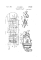
- Fig. 1 is a plan view of a wing unit constructedin accordance with the present in vention; a portion of the wing covering being broken away;
- Fig. 2 is a plan view of a portion of the wing structure with the wing section auxil- Fig. 3 is a sectional view showing that part or portion of the wing structure illustrated in Fig. 2; v
- Fig. "fl; is a view similar to Fig. 3; the wing section auxiliary wing being shown extended Fig. 5 a perspective view of the cable connection extending longitudinally of the wing-and fastenedto the auxiliary wingfor maintaining parallel relation between it and the wing section main Wing;
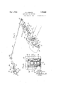
- Fig. 6 is a face view of the forward roller mounting
- Fig. 7 is a perspective view of the rear roller mounting
- Fig.8 is a perspective view of the lock means by whichthe auxiliary wing is locked in its retracted position.
- the wing structure main wing in its preferred embodiment, comprises a forward wing beam 10, a rear wing beam 11, and such other conventional structural wing frame members as ribs 12, brace wires 13, wing covering 14, etc. Fastened to said wing section main wing, and adjustable or movable toward and from the leading edge thereof,
- auxiliary wing is the wing section auxiliary wing 15. Movements of said auxiliary wing are entirely a11- tomatic and are brought about thru aerodynamic reasons now well known.
- the means for supporting the auxiliary wing 15 in the position indicated comprises "a plurality of arcuate supportarms 16, each of which at its forward end, ispivotally fastened as at 17 to the auxiliary wing, and at its opposite end, is let thru the forward wingbeam, 10, suitable openin s 18 being formed in said wing'beam for t is purpose.
- the ivot point 17 of each support arm is locate adacent to the leading edge of said auxiliary wing, and said auxiliary wingrat a point hehind and above its leading edge has 'pivotally fastened thereto as at 19 a plurality of link bolts 20,0ne for each sup rt arm.
- the link Its 20 penetrate the support arms and have mounted" thereon nuts 21-21 by means of which the link bolts are locked and. adjusted.
- the link bolts 20 By varying the effective length of the link bolts 20 the angular position of the auxiliarywing 15 with respect to the ma in'wing may be adjusted as desired.
- the support arms 16 are both held f0r sliders' 22 are preferably vertically adjustable,
- rollers 23 are preferably fixed.
- shock absorbers 32 are provided at the inner extremities of the rear extensions 25 of the several fittings.
- each shock absorber consists of a pair of rubber blocks positioned one at each side of the rear rollers 23' in the direct path of movement of the support arms 16.
- the support arms 16 carry at their inner ends abutment fittings 33, the lateral portions of which directly bear on the shock absorbers 32 in the extended position of the auxiliary wing.
- Said fittings 33 also carry eye-ends 34 bolted as at 35 to the laterally projecting fitting; portions; The purpose of such eye-end fittings will be laterdisclosed.
- one or more shims 36 may be;
- a tdrque tube or shaft 37 extends lengthwise the wing structure and is mounted in suitable bearings 38. In longitudinal alignment with each support arm 16 said tube or shaft 37 has mounted thereon appropriate hook fittings 39 which are adapted to engage with the eye-ends 34 at the inner arm ends. With the auxiliarywin retracted, the hook fittings 39 may be rotated to engage the eye-ends to thus prevent the outward or forward extension of the auxiliary wing.
- an endless cable 40' is provided. Said cable, throughout the major portion of its length, extends lengthwise the wing and is preferably fastened to certain of v the support arms which are distantly removed one from the other: Said cable is fastened to one said support arm as at 41.
- the cable 40 is thus endless and no matter what forces arebrou'ght to bearon the auxiliary wing in-its automatic operation, its
- a. wing section main wing including as a structural element thereof a win beam, a longitudinally adjustable wing section aux iliary wing mounted. in advance of the leading edge of said main wing, a su port arm pivotally fastened at its forwar end to said auxiliary wing, said support arm being carried thru said wing beam at its opposite end, a fitting wrapped around and extending rearw ai-dly beyond said wing beam, non adjustable rollers carried by the rearwardly extending portion of said fittin and adjustable rollers carried by that ortlon of said fitting extending forwardly 0 said wing beam, said'rollers, in each instance, being directly engagable with" said support arm to guide and hold it, and hence the auxiliary wing, both during and in all positions of adjustment, and said adjustable rollers be ing vertically adjustable to vary the angular position of said support arm, and hence the vertical position of said auxiliary wing in its relation to said main
- a wing section main wing an angularly adjustable wing section auxiliary wing mounted in advance of the leading edge of said main wing, a support arm slidably mounted in said wing section main wing and to which said auxiliary wing is pivotally fastened at a point in the vicinity of its leadingedge, and adjustable means carried by said support arm and pivotally fastened to said auxiliary wing at a point remote from its point of attachment to said support arm.
- a wing section main wing an, angularly adjustable wing section auxiliary wing mounted in advance of the leadingedge of said main wing, a support arm to which said auxiliary wing is pivotally fastened, a link; connection between sai support arm and said auxiliary wing. and means for varying the effective length of said linkconnection'.
- a wing section main wing a wing section auxiliary wing mounted in advanced the leading edge of said main wing, said auxiliary wing being movable automatically under the influence of changes-1n air pressures from a retracted position, close up against the leading edge of said main wingto an extended position spacedforwardly thereof, support arms to which said auxiliary wing is fastened and by means oiilzwhich it is guided in its movement, and a flexible interconnection between certain of said support arms for corelating the movements thereof during such.
- a wing section main wing a wing section auxiliary I wing mounted in advance of the leading edge of said main wing, said auxiliary wing being.
- a support arm for said auxiliary wing movable from a retracted position close up against theleading edge of said main wing to an extended position spaced forwardly there of, a support arm for said auxiliary wing, said support arm being carried at its rear end well within said main wing, a manually rotatable shaft extending into said main wing at substantially a right-angle to said support arm, and means carried by said shaft to engage and releaseably lock said support arm, and hence said auxiliary wing in its retracted position of adjustment.
- a main wing In an aeroplane, a main wing, an auxiliary wing, means for slidably supporting said auxiliary wing upon said main wing for movement away from and toward said main wing whereby a slot may be opened and closed adjacent to the leading edge of the combined airfoil, means for moving the nose of. said auxiliary wing to vary the relative height thereof with reference to the main wing, and means for varying the angle of the auxiliary wing with respect to the main wing.
- a wing section main wing having a forward wing beam, a wing section auxiliary wing mounted at the leading edge of said main wing and adapted to move toward and from said leading edge of the main wing to provide a slot between the auxiliary wing and the main wing at selected timesra set of roller bearings mounted upon said wing beam and disposed.
- roller bearing of each set being disposed above its cooperating roller bearing
- a wing section main wing having a forward wing beam, a'wing section auxiliary wing mounted at the leading edge of said main wing and 10 adapted to move toward and from said leading edge of the main win to provide a slot between the auxiliary wing and the main wing at selected times, a set of roller bearings mounted upon said Wing beam and disposed adjacent the forward face thereof, a second set of roller bearings mounted upon said wing beam and disposed adjacent the rear face thereof, one roller bearing of each set being 'disposed above its cooperating roller bearing,
- a wing section main wing a wing section auxiliary wing mounted in advance of the leading edge of said main wing, said auxiliary wing being movable from a retracted position close up 85 against the leading edge of said main wing to an extended position spaced forwardly thereof, a support for said auxiliary wing slidably mounted in said wing section main wing, a torque tube carried by said main 40 wing, a hook mounted upon said tube, and an eye-end carried by saidsupport and adapted to receive said hook to look the auxiliary wing in its retracted position.
Landscapes
- Engineering & Computer Science (AREA)
- Aviation & Aerospace Engineering (AREA)
- Blinds (AREA)
Description
may 1932. R. R. OSBORN mw w AEROPLANE WING STRUCTURE Filed March 26, 1929 3 Sheets-Sheet l A. H i." l.
AH-W
BY W
ATTORN EY RoeERT RDJB'ORH .1
E932' w. R. 0550mm AEROPIQANE WING STRUCTURE Filed March 26, 1929 3 SheetsSheet 2 mm Q, A R
@w k w QM a a we 8 QUE May 3, 1932., R R. osBoFm 1,356,080
AEROPLANE WING STRUCTURE Fileii March .26, 1929 3 Sheets-Sheet 3 N v INVENTOR d9. ROBERT RQSBORH- ATTORNEY Patented May 3, 1932 UNITED STATES PATENT OFFICE ROBERT It. OSBOBN, OF GARDEN CITY, NEW YORK, ASSIGNOR-TO GURTISS AEROP LANE & MOTOR COMPANY, INC., A. CORPORATION OF NEW YORK AEROPLANE WING STRUCTURE Application filed March 26, 1829. Serialli'o. 849,927.
My invention relates to wing structures for aeroplanes and more particularly to slotted aeroplane wings, i. e., 'wings including a wing structure main wing and a wing structure auxiliary wing, the latter being movable to provide, under certain operating conditions, a transversely extending open slot within and adjacent to the leading edge of the Wing.
An object of the invention is to provide an improved mounting for the wing structure auxiliary wing whereby its longitudinal adjustment is rendered positive and unfailingysaid mounting, in the preferred embodiment of the invention, comprising'a plurality of arcuate support arms, ball bearing roller supports by means of which said arms are guided during wing adjustment, simplified adjustments for varying the angle of incidence of said auxiliary wing as well as its vertical position with respect to the leading edge of said main wing, means for maintaining said auxiliary wing at all times in parallelism with said main wing, means for absorblng shocks due to the sudden forward movement of said auxiliary wing, and means for locking said auxiliary wing in its retracted position, and for releasing it when and as desired. f
Other objects and advantages of the invention, likewise of a structural nature, will be hereinafter more particularly set forth.
In the drawings, wherein like reference characters denote like or corresponding parts,
Fig. 1 is a plan view of a wing unit constructedin accordance with the present in vention; a portion of the wing covering being broken away;
Fig. 2 is a plan view of a portion of the wing structure with the wing section auxil- Fig. 3 is a sectional view showing that part or portion of the wing structure illustrated in Fig. 2; v
Fig. "fl; is a view similar to Fig. 3; the wing section auxiliary wing being shown extended Fig. 5 a perspective view of the cable connection extending longitudinally of the wing-and fastenedto the auxiliary wingfor maintaining parallel relation between it and the wing section main Wing;
Fig. 6 is a face view of the forward roller mounting;
Fig. 7 is a perspective view of the rear roller mounting, and
Fig.8 is a perspective view of the lock means by whichthe auxiliary wing is locked in its retracted position.
The wing structure main wing, in its preferred embodiment, comprises a forward wing beam 10, a rear wing beam 11, and such other conventional structural wing frame members as ribs 12, brace wires 13, wing covering 14, etc. Fastened to said wing section main wing, and adjustable or movable toward and from the leading edge thereof,
is the wing section auxiliary wing 15. Movements of said auxiliary wing are entirely a11- tomatic and are brought about thru aerodynamic reasons now well known.
The means for supporting the auxiliary wing 15 in the position indicated comprises "a plurality of arcuate supportarms 16, each of which at its forward end, ispivotally fastened as at 17 to the auxiliary wing, and at its opposite end, is let thru the forward wingbeam, 10, suitable openin s 18 being formed in said wing'beam for t is purpose. To the end that said auxiliary wing maybe adjusted as to angle of incidence, the ivot point 17 of each support arm is locate adacent to the leading edge of said auxiliary wing, and said auxiliary wingrat a point hehind and above its leading edge has 'pivotally fastened thereto as at 19 a plurality of link bolts 20,0ne for each sup rt arm. As indicated in Fig. 5, the link Its 20 penetrate the support arms and have mounted" thereon nuts 21-21 by means of which the link bolts are locked and. adjusted. By varying the effective length of the link bolts 20 the angular position of the auxiliarywing 15 with respect to the ma in'wing may be adjusted as desired.
. a The support arms 16 are both held f0r sliders' 22 are preferably vertically adjustable,
whereas the rollers 23 are preferably fixed.
- As a support for the two sets of rollers, a
1 mounted. At its forward end said rearwardly extending portion 25 bears squarely against the rear face of the forward wing beam 10 and the support arm 16 which penetrates the beam 10 at the point of fitting attachment passes entirely thru its extended length. At the top and bottom of said beam, straps 27 are provided, the straps in each instance, being carried forwardly to overhang the forward face of the beam, and by means of brackets 28 -28 formed on the strap ends, provide upon the forward face of said beam a retaining means for an adjustable fitting 29 upon which the iorward rollerbearings 22 are mounted. Said racket 29, by means of adjustable screws 3030 and lock nuts 31, is held in its adjusted position; As the rollers 22 are carried by said bracket 29, obviously any adjustment accorded said braclget is imparted to the support arm extending therethru, which adjustment is in turn imparted to the wing section auxiliary wing 15 that its leading edge may beraised and lowered (within certain limits) as desired. A fitting thus-formed not only provides for the desired spacing of the roller bearings, but it acts also as ameans for reinforcing the forward wing beam at the point or points where the openings 18 are provided. To take care of shocks due to the more or less sudden forward movement of the auxiliary wing 15,.shock absorbers 32 are provided at the inner extremities of the rear extensions 25 of the several fittings. As herein illustrated each shock absorber consists of a pair of rubber blocks positioned one at each side of the rear rollers 23' in the direct path of movement of the support arms 16. The support arms 16 carry at their inner ends abutment fittings 33, the lateral portions of which directly bear on the shock absorbers 32 in the extended position of the auxiliary wing. Said fittings 33 also carry eye-ends 34 bolted as at 35 to the laterally projecting fitting; portions; The purpose of such eye-end fittings will be laterdisclosed. As a means of,
adjustment, one or more shims 36 may be;
used to vary? the distance between the fab'utment fittings and the shock'absorbers 32. By
" thus varying the distance betweenthe parts mentioned the-extent to which the auxiliary v detail in its present preferred embod ment, 1t will'be obvious to those skilled in the art after wing Inlay .proj e'cted forwardly may be varied. w
Since dt is, uite desirable' underf certain .operatinggconditions to lock' the auxiliary wingin its;retractedposition,.a suitable lock 2 11 132? I 199k: pile-3933115 'i rf y co trolled f om rovidedfithe operation of which the pilots seat. A tdrque tube or shaft 37 extends lengthwise the wing structure and is mounted in suitable bearings 38. In longitudinal alignment with each support arm 16 said tube or shaft 37 has mounted thereon appropriate hook fittings 39 which are adapted to engage with the eye-ends 34 at the inner arm ends. With the auxiliarywin retracted, the hook fittings 39 may be rotated to engage the eye-ends to thus prevent the outward or forward extension of the auxiliary wing.
It has further been found in practice that it is quite desirable to provide a means for maintaining the auxiliary wing at all times in parallelism with theleading edge of the main wing. This is particularly true where the leading edge of the main wing, and hence the auxiliary wing, is provided with a sweepback at its leading edge? That this parallel motion device may be made as light and simple as possible, an endless cable 40' is provided. Said cable, throughout the major portion of its length, extends lengthwise the wing and is preferably fastened to certain of v the support arms which are distantly removed one from the other: Said cable is fastened to one said support arm as at 41. From its point of attachment at 41 it extends forwardly over a pulley 42 carried by one of the fittings 24, thence rearwardly to a pulley 43. From said pulley 43 the cable extends l'ongitudinally of the wing to a third pulley 44,
from which point it is carried forwardly to a point of attachment to a second or the diswhich the last mentioned support arm ex-' tantly removed support arm where it is fas- 1 tends, and thence back again over the pulleys 44 and 43 to its point of beginning at 41. The cable 40 is thus endless and no matter what forces arebrou'ght to bearon the auxiliary wing in-its automatic operation, its
movement is equalized and said wing is at all times held parallel ,to the leading edge of the main wing.
It will be observed from the foregoing that angular adjustment as well as vertical adj ustment of the auxiliary wing 15 may be eifected; that the entire hook-up may be installed on conventional wing structures without s ub-v .stantial modificatidn; and that provision ismade for 'the locking ofthe auxiliary wing i'n'its retracted positiol tially the entire mechanism is enclosed within the confines of the main wing.
While'l have described my invention in understanding my 'invention, 'that various coverall' such modifications and changes."
changesand modifications may be made there- Moreover, substan- 12 -WhatIclaimis: A
I. In an aeroplane WlIIg StIfUCl'MI'G, a. wing section main wing including as a structural element thereof a win beam, a longitudinally adjustable wing section aux iliary wing mounted. in advance of the leading edge of said main wing, a su port arm pivotally fastened at its forwar end to said auxiliary wing, said support arm being carried thru said wing beam at its opposite end, a fitting wrapped around and extending rearw ai-dly beyond said wing beam, non adjustable rollers carried by the rearwardly extending portion of said fittin and adjustable rollers carried by that ortlon of said fitting extending forwardly 0 said wing beam, said'rollers, in each instance, being directly engagable with" said support arm to guide and hold it, and hence the auxiliary wing, both during and in all positions of adjustment, and said adjustable rollers be ing vertically adjustable to vary the angular position of said support arm, and hence the vertical position of said auxiliary wing in its relation to said main wing.
2. In an aeroplane wing structure, a wing section main wing, an angularly adjustable wing section auxiliary wing mounted in advance of the leading edge of said main wing, a support arm slidably mounted in said wing section main wing and to which said auxiliary wing is pivotally fastened at a point in the vicinity of its leadingedge, and adjustable means carried by said support arm and pivotally fastened to said auxiliary wing at a point remote from its point of attachment to said support arm.
3. In an aeroplane wing structure. a wing section main wing, an, angularly adjustable wing section auxiliary wing mounted in advance of the leadingedge of said main wing, a support arm to which said auxiliary wing is pivotally fastened, a link; connection between sai support arm and said auxiliary wing. and means for varying the effective length of said linkconnection'. v
4. In an aeroplane wing structure, a wing section main wing, a wing section auxiliary wing mounted in advanced the leading edge of said main wing, said auxiliary wing being movable automatically under the influence of changes-1n air pressures from a retracted position, close up against the leading edge of said main wingto an extended position spacedforwardly thereof, support arms to which said auxiliary wing is fastened and by means oiilzwhich it is guided in its movement, and a flexible interconnection between certain of said support arms for corelating the movements thereof during such.
wing adjustment.
5. In an aeroplane wing structure, a. wing section main wing, a wing section auxiliary wing mounted in advance of the leading edge of said main wing, said auxiliary wing being movable automatically under the influence of changes of air pressures from a retracted position close up against the leading edge of said main wing to an extended osition spaced forwardly thereof, and flexile means extending from one point to another along the length of said auxiliary wing edge of said main wing, said auxiliary wing being movable from a retracted position close up against the leading edge of said main wing to an extended position spaced forwardly thereof, and an endless cable connection extending from one point to another along the length of said auxiliary wing for maintaining it in parallel relation to the leading edge of said main wing in all positions of auxiliary wing ad ustment.
7. In an aeroplane wlng structure, a wing section main wing, a wing section auxiliary I wing mounted in advance of the leading edge of said main wing, said auxiliary wing being.
movable from a retracted position close up against theleading edge of said main wing to an extended position spaced forwardly there of, a support arm for said auxiliary wing, said support arm being carried at its rear end well within said main wing, a manually rotatable shaft extending into said main wing at substantially a right-angle to said support arm, and means carried by said shaft to engage and releaseably lock said support arm, and hence said auxiliary wing in its retracted position of adjustment. 8. In an aeroplane, a main wing, an auxiliary wing, means for slidably supporting said auxiliary wing upon said main wing for movement away from and toward said main wing whereby a slot may be opened and closed adjacent to the leading edge of the combined airfoil, means for moving the nose of. said auxiliary wing to vary the relative height thereof with reference to the main wing, and means for varying the angle of the auxiliary wing with respect to the main wing.
9. In an aeroplane wing structure, a wing section main wing having a forward wing beam, a wing section auxiliary wing mounted at the leading edge of said main wing and adapted to move toward and from said leading edge of the main wing to provide a slot between the auxiliary wing and the main wing at selected timesra set of roller bearings mounted upon said wing beam and disposed.
beam and disposed adjacent the rear face thereof, one roller bearing of each set being disposed above its cooperating roller bearing,"
and an arcuate supporting arm for said auxiliary wing extending through said beam and adapted to move fore and aft between thecooperating roller bearings of each set,
whereby said arm'is guided and supported 6 by said roller bearings.
10: In an aeroplane wing structure, a wing section main wing having a forward wing beam, a'wing section auxiliary wing mounted at the leading edge of said main wing and 10 adapted to move toward and from said leading edge of the main win to provide a slot between the auxiliary wing and the main wing at selected times, a set of roller bearings mounted upon said Wing beam and disposed adjacent the forward face thereof, a second set of roller bearings mounted upon said wing beam and disposed adjacent the rear face thereof, one roller bearing of each set being 'disposed above its cooperating roller bearing,
and an arcuate supporting arm for said auxiliary wing extending through said beam and adapted to move fore and aft between the cooperating roller bearings of each set, whereby said arm is guided and supported by said 26 roller bearings, said bearings being disposed at all times within the main wing and said arm being disposed within the main wing when the auxiliary wing is in itsretracted position.
' 11. In an aeroplane wing structure, a wing section main wing, a wing section auxiliary wing mounted in advance of the leading edge of said main wing, said auxiliary wing being movable from a retracted position close up 85 against the leading edge of said main wing to an extended position spaced forwardly thereof, a support for said auxiliary wing slidably mounted in said wing section main wing, a torque tube carried by said main 40 wing, a hook mounted upon said tube, and an eye-end carried by saidsupport and adapted to receive said hook to look the auxiliary wing in its retracted position.
In testimony whereof I hereunto afiix my signature.
- ROBERT R. OSBORN.
Priority Applications (1)
| Application Number | Priority Date | Filing Date | Title |
|---|---|---|---|
| US349927A US1856080A (en) | 1929-03-26 | 1929-03-26 | Aeroplane wing structure |
Applications Claiming Priority (1)
| Application Number | Priority Date | Filing Date | Title |
|---|---|---|---|
| US349927A US1856080A (en) | 1929-03-26 | 1929-03-26 | Aeroplane wing structure |
Publications (1)
| Publication Number | Publication Date |
|---|---|
| US1856080A true US1856080A (en) | 1932-05-03 |
Family
ID=23374564
Family Applications (1)
| Application Number | Title | Priority Date | Filing Date |
|---|---|---|---|
| US349927A Expired - Lifetime US1856080A (en) | 1929-03-26 | 1929-03-26 | Aeroplane wing structure |
Country Status (1)
| Country | Link |
|---|---|
| US (1) | US1856080A (en) |
-
1929
- 1929-03-26 US US349927A patent/US1856080A/en not_active Expired - Lifetime
Similar Documents
| Publication | Publication Date | Title |
|---|---|---|
| US2086085A (en) | Aircraft control gear | |
| GB1294349A (en) | Improvements in or relating to high speed aircraft | |
| US2404956A (en) | Wing lift modification | |
| US1818000A (en) | Aerofoil operating mechanism | |
| US1856080A (en) | Aeroplane wing structure | |
| US1914092A (en) | Retractible landing gear | |
| US1894582A (en) | Retractable landing gear | |
| US1830429A (en) | Air craft control system | |
| US1512912A (en) | Aeroplane | |
| US2505652A (en) | Tail wheel actuated arresting hook | |
| US1727095A (en) | Aerial advertising and signaling device | |
| US2306015A (en) | Wing structure for aircraft | |
| GB210181A (en) | Improvements in or relating to aeroplanes | |
| US2383930A (en) | Retractable step | |
| US1834254A (en) | Aircraft | |
| US1855012A (en) | Aeroplane | |
| US1903752A (en) | Airplane | |
| US1322160A (en) | Coublay | |
| US1755540A (en) | Controllable auxiliary wing for airplanes | |
| DE1200691B (en) | Transverse drive surface with a forward slidable wing | |
| US1934992A (en) | Retractable landing gear | |
| US1743393A (en) | Aircraft | |
| US1874521A (en) | Airplane | |
| GB781059A (en) | Improvements relating to winged aerial targets | |
| GB562693A (en) | Retractable auxiliary wing elements |