US1856066A - Means for feeding fuel to an internal combustion engine - Google Patents
Means for feeding fuel to an internal combustion engine Download PDFInfo
- Publication number
- US1856066A US1856066A US645778A US64577823A US1856066A US 1856066 A US1856066 A US 1856066A US 645778 A US645778 A US 645778A US 64577823 A US64577823 A US 64577823A US 1856066 A US1856066 A US 1856066A
- Authority
- US
- United States
- Prior art keywords
- fuel
- chamber
- valve
- plunger
- engine
- Prior art date
- Legal status (The legal status is an assumption and is not a legal conclusion. Google has not performed a legal analysis and makes no representation as to the accuracy of the status listed.)
- Expired - Lifetime
Links
- 239000000446 fuel Substances 0.000 title description 121
- 238000002485 combustion reaction Methods 0.000 title description 16
- 230000035611 feeding Effects 0.000 description 22
- 230000001276 controlling effect Effects 0.000 description 8
- 230000006835 compression Effects 0.000 description 5
- 238000007906 compression Methods 0.000 description 5
- 239000007788 liquid Substances 0.000 description 3
- 230000001105 regulatory effect Effects 0.000 description 3
- 238000005507 spraying Methods 0.000 description 3
- 238000010276 construction Methods 0.000 description 2
- 238000003825 pressing Methods 0.000 description 2
- 210000000988 bone and bone Anatomy 0.000 description 1
- -1 distillate Substances 0.000 description 1
- 230000009977 dual effect Effects 0.000 description 1
- 239000000295 fuel oil Substances 0.000 description 1
- 239000002828 fuel tank Substances 0.000 description 1
- 230000005484 gravity Effects 0.000 description 1
- 239000003350 kerosene Substances 0.000 description 1
- 239000003921 oil Substances 0.000 description 1
- 230000000630 rising effect Effects 0.000 description 1
Images

Classifications
-
- F—MECHANICAL ENGINEERING; LIGHTING; HEATING; WEAPONS; BLASTING
- F02—COMBUSTION ENGINES; HOT-GAS OR COMBUSTION-PRODUCT ENGINE PLANTS
- F02M—SUPPLYING COMBUSTION ENGINES IN GENERAL WITH COMBUSTIBLE MIXTURES OR CONSTITUENTS THEREOF
- F02M43/00—Fuel-injection apparatus operating simultaneously on two or more fuels, or on a liquid fuel and another liquid, e.g. the other liquid being an anti-knock additive
-
- F—MECHANICAL ENGINEERING; LIGHTING; HEATING; WEAPONS; BLASTING
- F02—COMBUSTION ENGINES; HOT-GAS OR COMBUSTION-PRODUCT ENGINE PLANTS
- F02M—SUPPLYING COMBUSTION ENGINES IN GENERAL WITH COMBUSTIBLE MIXTURES OR CONSTITUENTS THEREOF
- F02M57/00—Fuel-injectors combined or associated with other devices
- F02M57/02—Injectors structurally combined with fuel-injection pumps
-
- F—MECHANICAL ENGINEERING; LIGHTING; HEATING; WEAPONS; BLASTING
- F02—COMBUSTION ENGINES; HOT-GAS OR COMBUSTION-PRODUCT ENGINE PLANTS
- F02M—SUPPLYING COMBUSTION ENGINES IN GENERAL WITH COMBUSTIBLE MIXTURES OR CONSTITUENTS THEREOF
- F02M2700/00—Supplying, feeding or preparing air, fuel, fuel air mixtures or auxiliary fluids for a combustion engine; Use of exhaust gas; Compressors for piston engines
- F02M2700/07—Nozzles and injectors with controllable fuel supply
- F02M2700/078—Injectors combined with fuel injection pump
Definitions
- flhis invention relates to improved means for feeding fuel to an internal combustion engine, particularly of the high compression type which may be operated on diderent as gasolene, kerosene, distillate, fuel oil, etc, it being more advantageous to operate the engine on the lower grades of fuel provided this can be fed to the engine in a suitable manner.
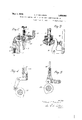
- Figure 1 is a reduced sectional view through an engine of the Gernandt type heretofore referred to, showing the fuel feeding means attached thereto.
- Figure 2 shows a modified form of a fuel injector or metering device.
- Figures 3,4 and 5 indicate various constructions or means for actuating the injector plunger.
- This mechanism consists of: a fuel chamber 8, a fuel pump plunger 9, the free end of which is positioned in a bore 10, and a fuel feed control needle 11, the lower end of "Which is positioned in an orifice 12 that opens from the fuel chamber 8 into fuel passageway 13, which in turn opens into a valve chamber 14, the'lower end of which is closed by a fuel feed check valve 15, the same being held in closed position by a spring 16.
- a duct 17 leads from the plunger cavity or bore 10 to the passage 13 and valve chamber 14, the outer endof the duct 17 being closed by a plug 18.
- A. port 19 leads from the fuel chamber 8 to the cavity or bore 10.
- a fuel tank 20 is connected by a pipe 21 to the fuel chamber 8.
- a slight pressure is placed in the tank 20 through the medium of a pipe 22 and the recess 23 in the plunger 6, all as described in the said Gernandt application heretofore referred to, but it will be understood that fuel may be fed to the chamber 8 by gravity or any other suitable means.
- the plunger 9 as shown in Fig. 1 is actuated by a pull rod 24 and lever 25, the same being pivoted at 26.
- the rod 24 can be actuated in any number of ways, for example in Fig. 1, it is shown connected to a lever 27 that is pivoted to a part of the engine frame, the lever 27 being actuated by the collar 28 carried on the compression plunger 6, said plunger being returned to normal position by spring 29, after its actuation by cam 30 carried on the crankshaft.
- Another way of operating the rod 24 is indicated in Fig. 3 in which the bushing 28 actuateslever 31 in a somewhat different manner from the way lever 27 is actuated in Fig; 1. Still other ways are indicated in Figs.
- the spring loaded check valve 15 acts as a nozzle for spraying fuel into the fuel depository.
- pressure is applied to the chamber 14:, as above described, a certain amount of the fuel is passed through the orifice 12, depending on theposition of the valve 11, back to the fuel chamber 8. Consequently the amount of fuel metered to the fuel depository 33 is controlled by the tension of spring 16 and the size of the by-pass orifice 12; the greater the opening of the bypass orifice 12, the greater the amount of fuel leaking back to 1 the fuel chamber 8 and the less amount of through the orifice 12.
- Means for feeding fuel to an internal combustion engine comprising: a plug having a valve chamber with one end opening in the direction of the engine cylinder with a valve normally closing the cylinder end of said chamber; a fuel chamber, a passage extending from'the valve chamber and having an orifice opening into the fuel chamber, a bore having a plunger positioned therein, said bore having a duct communicating with the passage, a port leading from said fuel chamber to said bore at a point ahead of said plunger when in its retracted position, means for controlling the size of said orifice and means for actuating said plungerfor applying pressure to the fuel in the valve chamber for the purpose described.
- Means for feeding fuel to an internal combustion engine comprising: a plug having a valve chamber with one end opening in engine cylinder with a valve normally closing the cylinder end of said chamber; a fuel chamber, a bore having a plunger positioned therein, a port leading from said fuel chamber to said bore wherebythebore is filled with fuel when the said plunger is in its retracted position, a duct leading fromsaid valve chamber into said bore, means for actuating said plunger at the proper time to apply pressure to the fuel in the valve chamber, a by-pass orifice, and means for controlling its size for determining the amount of pressure appliedto the fuel in the valve chamber.
- Means for feeding fuel to an internal combustion engine comprising: a plug having a valve chamberwith one end opening in the direction of the engine cylinder, a spring loaded check valve for closing the said opening and furtheracting as a nozzle for spraying fuel that is to feed said engine cylinder, a fuel chamber, a bore having a plunger positioned therein, a port leading from said fuel chamber to said bore whereby the bore is filled with fuel when the said plunger is in its retracted position, a duct leadingfrom ltll its
- valve chamber and communicatin with said bore, means for actuating said p unger at the proper time to apply pressure to the fuel in the valve chamber, and means for de termining the amount of pressure applied to the fuel and valve in the valve chamber.
- Means for feeding fuel to an internal combustion engine comprising: a plug having a valve chamber with one end opening in the direction of the engine cylinder, a spring loadedcheclr valve for closing the said opening and further acting as a nozzle for spraying fuel that is to feed said engine cylinder, a fuel chamber, a bore having aplunger positioned therein, a port leading from said fuel chamber to said bore whereby the bore is filled with fuel when the said plunger is in its retracted position, a duct leading from said valve chamber and communicating with said bore, means for actuating said plunger at the proper time to apply pressure to the fuel in the valve chamber, a bypass to determine the pressure applied to the fuel and valve in the valve chamber, and a needle valve for controlling the bypass.
- Means for feeding fuel to an internal combustion engine comprising: a plug for fitting into the head of the engine cylinder, said plug carrying within itself, a valve chamber with one end opening into a fuel depository adjacent the engine cylinder, a valve normally closing the depository end of said chamber, a fuel chamber, a bore having a plunger positioned therein, a port leading from said fuel chamber to said bore whereby the bore is filled with fuel when the said plunger is in its retracted position, a duct leading from said valve chamber into communication with said bore, a by-pass orifice between the fuel chamber and valve chamber, and a load regulating valve for controlling said by-pass orifice; and means for actuating said plunger at the proper time to apply pres- .Zure to the fuel and valve in the valve cham- '6.
- Means for feeding fuel to an internal combustion engine comprising: a plug having a valve chamber with one end opening in the direction of the engine cylinder with a valve normally closing the engine end of said chamber; a fuel chamber, a bone having a plunger positioned therein, a port leading from said fuel chamber to said bore, a duct leading from said valve chamber into communication with said bore, means for actuating said plunger at the proper time to apply pressure to the fuel in the valve chamber, and means for controlling the amount of fuel passed by said valve toward the engine cylinder cons1sting of; a spring on said valve and a by-pass orifice between the fuel chamber and the valve chamber with means for controlling the size of said orifice.
- Means for feeding fuel to an internal combustion engine comprising, a fuel feed ing chamber, a valve chamber and a plurality of passages connecting the chambers, a member for applying pressure to fuel in the valve chamber, said member being movable into a position to obstruct one of the passages and means positioned in another of sa d passages for metering fuel from the valve chamber back to the fuel chamber when pressure is applied to the fuel in the valve chamber.
- Means for feeding fuel to an internal combustion engine comprising, a fuel feeding chamber, a valve chamber having dual connections with said fuel feeding chamber, a passageway fromsaid valve chamber to the engine, a member arranged to obstruct one of said connections and to simultaneously apply pressure to the fuel in the fuel chamber, and means restricting the opening in the other connection between the valve chamber and fuel chamber for controlling the amount of fuel leaking back to the fuel chamber through said other connection when ressure is applied to fuel in the valve cham r and thereby controlling the amount of fuel fed to the engine.
- Fuel feeding means including, in combination, two pumps having oppositely ar ranged pistons moved in timed relation and communicating with a common outlet, one pump being arranged to compress a fuelinjecting gas and the other to supply liquid fuel to said gas, and a bypass from a point between the fuel compressing piston and the common outlet for returning a portion of the liquid fuel to a point back of the fuel pump, whereby the amount of fuel supplied to the gas is regulated.
Landscapes
- Engineering & Computer Science (AREA)
- Chemical & Material Sciences (AREA)
- Combustion & Propulsion (AREA)
- Mechanical Engineering (AREA)
- General Engineering & Computer Science (AREA)
- Fuel-Injection Apparatus (AREA)
Description
1,856,066 MEANS FOR FEEDING FUEL TO AN INTERNAL COMBUSTION ENGINE May 3, 1932. c. E. BATHRICK 1923 2 Sheets-Sheet Filed June 16 .H. m w y 5 l a May 3,1932. c. E. BATHRICK GINE MEANS FOR FEEDING FUEL TO AN INTERNAL COMBUSTION EN Filed June 16, 1923 2 Sheets-Sheet grades of fuel, such ldrernandt type u of the engine cylinder and its piston, talren W the depository and then lf'ntented May 3, i932 E. IlBATHfiICK,
F SQ'UTH BEND, KNDIMA,
Parent orrrce AQSIGNUR T0 GERNANDW MUTQR UORIU MWIUN, WE EHIUAGO, ILLINOIE;
Application. filed June It,
flhis invention relates to improved means for feeding fuel to an internal combustion engine, particularly of the high compression type which may be operated on diderent as gasolene, kerosene, distillate, fuel oil, etc, it being more advantageous to operate the engine on the lower grades of fuel provided this can be fed to the engine in a suitable manner.
it is, therefore, the principal object of my invention to provide a simple means for ethciently feeding or metering definite quantities of any kind of liquid fuel to an internal combustion engine.
in order to illustrate the application of my invention, l have shown the same in comliiination with an engine such as shown and described in Grernandt application 638,5 l i tiled April 20, 1923, but it is to be clearly understood that the fuel metering device or devices described herein can be used in various combmations, and the applicatlon is,
therefore, not limited tov an engine of wherein, through the design with other details, products of combustion are trapped in the fuel depository and the compression chamber adjacent the engine cylinder, after which the fuel is injected into the trapped products of combustion are compressed, forcing the fuel from the depository into the engine'cylinder at the proper time. a
My invention will be clearly understood by reference to the attached drawings in which:
Figure 1 is a reduced sectional view through an engine of the Gernandt type heretofore referred to, showing the fuel feeding means attached thereto.
Figure 2 shows a modified form of a fuel injector or metering device.
Figures 3,4 and 5 indicate various constructions or means for actuating the injector plunger.
lit is to be understood the drawings are merely illustrative and are not to be taken as showing exact proportions.
in the drawings like numbers refer to corresponding parts in the various views, 1
19563. Serial No. @453'3'8.
representing an engine cylinder having a piston '2," connecting rod 3, crank shaft '4 and fly-wheel 5. Adjacent the engine cylinder 1 is a compression chamber having a plunger {5 therein. Fitting within the end of the cyllnder is a fuel plug 7 which, as per Fig. 1, carries the injector mechanism per se. This mechanism consists of: a fuel chamber 8, a fuel pump plunger 9, the free end of which is positioned in a bore 10, and a fuel feed control needle 11, the lower end of "Which is positioned in an orifice 12 that opens from the fuel chamber 8 into fuel passageway 13, which in turn opens into a valve chamber 14, the'lower end of which is closed by a fuel feed check valve 15, the same being held in closed position by a spring 16. A duct 17 leads from the plunger cavity or bore 10 to the passage 13 and valve chamber 14, the outer endof the duct 17 being closed by a plug 18. A. port 19 leads from the fuel chamber 8 to the cavity or bore 10.
A fuel tank 20 is connected by a pipe 21 to the fuel chamber 8. In the combination shown in Fig. 1 a slight pressure is placed in the tank 20 through the medium of a pipe 22 and the recess 23 in the plunger 6, all as described in the said Gernandt application heretofore referred to, but it will be understood that fuel may be fed to the chamber 8 by gravity or any other suitable means.
The plunger 9 as shown in Fig. 1 is actuated by a pull rod 24 and lever 25, the same being pivoted at 26. The rod 24 can be actuated in any number of ways, for example in Fig. 1, it is shown connected to a lever 27 that is pivoted to a part of the engine frame, the lever 27 being actuated by the collar 28 carried on the compression plunger 6, said plunger being returned to normal position by spring 29, after its actuation by cam 30 carried on the crankshaft. Another way of operating the rod 24 is indicated in Fig. 3 in which the bushing 28 actuateslever 31 in a somewhat different manner from the way lever 27 is actuated in Fig; 1. Still other ways are indicated in Figs. 4 and 5, in which the rod 241 is actuated by a cam 32, suitably formed and positioned on an operating part of the engine. So much depends Oil on the general design of the engine on which the fuel feeding means. is to be used that the ways for actuating the fuel plunger may be varied over wide limits, but when used with the Gernandt type of engine, the fuel plunger 9 is actuated at a time when the engine piston-is near the end of its working stroke or approximately 180 degrees from the position shown in F 1.
, Considering now the operation of my fuel feeding and metering system, fuel is supplied to the chamber 8 under slight pressure or other means as indicated and when the plunger 9 is in the position shown in Fig. 1 fuel will flow through the port 19 into the plunger cavity or bore 10, fuel duct 17, into the valve chamber 14, also through the orifice 12 and passage 13, filling the entire space from the check valve 15 back to and including the fuel chamber 8. On the compression stroke of the plunger 9, port 19 is closed and a pressure is built up in the fuel duct 17 and chamber 14 against the check valve 15. At the proper time, due to the position of the engine piston and pressure on the valve 15, the same will open and a definite amount of fuel is metered or sprayed into the fuel depository 33, thus the spring loaded check valve 15 acts as a nozzle for spraying fuel into the fuel depository. At the same time that pressure is applied to the chamber 14:, as above described, a certain amount of the fuel is passed through the orifice 12, depending on theposition of the valve 11, back to the fuel chamber 8. Consequently the amount of fuel metered to the fuel depository 33 is controlled by the tension of spring 16 and the size of the by-pass orifice 12; the greater the opening of the bypass orifice 12, the greater the amount of fuel leaking back to 1 the fuel chamber 8 and the less amount of through the orifice 12. Should a applied that is sufiicient to reduce the speed, a longer time is thereby allowed fuel is forced past the check valve 15 into the fuel depository. Conversely, the' smaller the bypass orifice 12, the greater will be the amount of fuel that will be forced into the fuel depository on the opening of the valve 15. This arrangement has another decided advantage, and that is a time element in the by-passing of surplus fuel past the. needle valve, which is of considerable advantage when a governor is used in connection therewith. For example, at a given number of engine revolutions per minute a certain definite quantity of fuel would be bypassed load be for by-passing and consequently a smaller portion of fuel would be injected into the fuel depository. In the form of fuel injector shown in Fig, 2, the principle of operation is exactly the same as that shown in Fig. 1, the lower nosition of fuel plunger 9 being indicated by dotted line 34.
It is evident that the detail construction of the direction of the the fuel plug and its associated mechanigm and the manner of actuating certain parts of said mechanism is susceptible of many changes, a number of which have already been indicated, for it will be apparent by referring to Fig. 2 that the fuel plunger and needle valve with the associated parts may be mounted even down close to the crank-\ shaft and the plug 7 carry only the valve 15. Furthermore the port 19 may be controlled by a suitable check valve so that when pressure is set upin the plunger chamber 10 by the plunger 9 this check valve will close the port 19 and prevent any return of fuel back through this assage to the fuel chamber 8; consequentlydo not wish to be limited to the exact details shown and described herein. Having thus described my invention, what I claim is:
I. Means for feeding fuel to an internal combustion engine, comprising: a plug having a valve chamber with one end opening in the direction of the engine cylinder with a valve normally closing the cylinder end of said chamber; a fuel chamber, a passage extending from'the valve chamber and having an orifice opening into the fuel chamber, a bore having a plunger positioned therein, said bore having a duct communicating with the passage, a port leading from said fuel chamber to said bore at a point ahead of said plunger when in its retracted position, means for controlling the size of said orifice and means for actuating said plungerfor applying pressure to the fuel in the valve chamber for the purpose described.
2. Means for feeding fuel to an internal combustion engine, comprising: a plug having a valve chamber with one end opening in engine cylinder with a valve normally closing the cylinder end of said chamber; a fuel chamber, a bore having a plunger positioned therein, a port leading from said fuel chamber to said bore wherebythebore is filled with fuel when the said plunger is in its retracted position, a duct leading fromsaid valve chamber into said bore, means for actuating said plunger at the proper time to apply pressure to the fuel in the valve chamber, a by-pass orifice, and means for controlling its size for determining the amount of pressure appliedto the fuel in the valve chamber.
3. Means for feeding fuel to an internal combustion engine, comprising: a plug having a valve chamberwith one end opening in the direction of the engine cylinder, a spring loaded check valve for closing the said opening and furtheracting as a nozzle for spraying fuel that is to feed said engine cylinder, a fuel chamber, a bore having a plunger positioned therein, a port leading from said fuel chamber to said bore whereby the bore is filled with fuel when the said plunger is in its retracted position, a duct leadingfrom ltll its
said valve chamber and communicatin with said bore, means for actuating said p unger at the proper time to apply pressure to the fuel in the valve chamber, and means for de termining the amount of pressure applied to the fuel and valve in the valve chamber.
4t. Means for feeding fuel to an internal combustion engine, comprising: a plug having a valve chamber with one end opening in the direction of the engine cylinder, a spring loadedcheclr valve for closing the said opening and further acting as a nozzle for spraying fuel that is to feed said engine cylinder, a fuel chamber, a bore having aplunger positioned therein, a port leading from said fuel chamber to said bore whereby the bore is filled with fuel when the said plunger is in its retracted position, a duct leading from said valve chamber and communicating with said bore, means for actu ating said plunger at the proper time to apply pressure to the fuel in the valve chamber, a bypass to determine the pressure applied to the fuel and valve in the valve chamber, and a needle valve for controlling the bypass.
5. Means for feeding fuel to an internal combustion engine, comprising: a plug for fitting into the head of the engine cylinder, said plug carrying within itself, a valve chamber with one end opening into a fuel depository adjacent the engine cylinder, a valve normally closing the depository end of said chamber, a fuel chamber, a bore having a plunger positioned therein, a port leading from said fuel chamber to said bore whereby the bore is filled with fuel when the said plunger is in its retracted position, a duct leading from said valve chamber into communication with said bore, a by-pass orifice between the fuel chamber and valve chamber, and a load regulating valve for controlling said by-pass orifice; and means for actuating said plunger at the proper time to apply pres- .Zure to the fuel and valve in the valve cham- '6. Means for feeding fuel to an internal combustion engine comprising: a plug having a valve chamber with one end opening in the direction of the engine cylinder with a valve normally closing the engine end of said chamber; a fuel chamber, a bone having a plunger positioned therein, a port leading from said fuel chamber to said bore, a duct leading from said valve chamber into communication with said bore, means for actuating said plunger at the proper time to apply pressure to the fuel in the valve chamber, and means for controlling the amount of fuel passed by said valve toward the engine cylinder cons1sting of; a spring on said valve and a by-pass orifice between the fuel chamber and the valve chamber with means for controlling the size of said orifice.
7. Means for feeding fuel to an internal combustion engine comprising, a fuel feed ing chamber, a valve chamber and a plurality of passages connecting the chambers, a member for applying pressure to fuel in the valve chamber, said member being movable into a position to obstruct one of the passages and means positioned in another of sa d passages for metering fuel from the valve chamber back to the fuel chamber when pressure is applied to the fuel in the valve chamber.
8. Means for feeding fuel to an internal combustion engine com rising, a fuel feeding chamber, a valve cham er, two passageways connecting the chambers, a valve in the valve chamber, a yielding means for closing the valve, a member designed to appl pressure to fuel in the valve chamber an movable into a position to obstruct one of the passages, means in the other passage for metering and regulating the flow of a portion of the fuel from the valve chamber to the feeding chamber when pressure is applied to the fuel in the valve chamber,
9. Means for feeding fuel to an internal combustion engine comprising, a fuel feeding chamber, a valve chamber having dual connections with said fuel feeding chamber, a passageway fromsaid valve chamber to the engine, a member arranged to obstruct one of said connections and to simultaneously apply pressure to the fuel in the fuel chamber, and means restricting the opening in the other connection between the valve chamber and fuel chamber for controlling the amount of fuel leaking back to the fuel chamber through said other connection when ressure is applied to fuel in the valve cham r and thereby controlling the amount of fuel fed to the engine.
10. Fuel feeding means including, in combination, two pumps having oppositely ar ranged pistons moved in timed relation and communicating with a common outlet, one pump being arranged to compress a fuelinjecting gas and the other to supply liquid fuel to said gas, and a bypass from a point between the fuel compressing piston and the common outlet for returning a portion of the liquid fuel to a point back of the fuel pump, whereby the amount of fuel supplied to the gas is regulated.
In testimony whereof, I afiix my signature.
CHARLES E. BATHRICK.
Priority Applications (1)
| Application Number | Priority Date | Filing Date | Title |
|---|---|---|---|
| US645778A US1856066A (en) | 1923-06-16 | 1923-06-16 | Means for feeding fuel to an internal combustion engine |
Applications Claiming Priority (1)
| Application Number | Priority Date | Filing Date | Title |
|---|---|---|---|
| US645778A US1856066A (en) | 1923-06-16 | 1923-06-16 | Means for feeding fuel to an internal combustion engine |
Publications (1)
| Publication Number | Publication Date |
|---|---|
| US1856066A true US1856066A (en) | 1932-05-03 |
Family
ID=24590439
Family Applications (1)
| Application Number | Title | Priority Date | Filing Date |
|---|---|---|---|
| US645778A Expired - Lifetime US1856066A (en) | 1923-06-16 | 1923-06-16 | Means for feeding fuel to an internal combustion engine |
Country Status (1)
| Country | Link |
|---|---|
| US (1) | US1856066A (en) |
Cited By (1)
| Publication number | Priority date | Publication date | Assignee | Title |
|---|---|---|---|---|
| US3391678A (en) * | 1967-04-03 | 1968-07-09 | Philip G. Luckhardt | Motive power system |
-
1923
- 1923-06-16 US US645778A patent/US1856066A/en not_active Expired - Lifetime
Cited By (1)
| Publication number | Priority date | Publication date | Assignee | Title |
|---|---|---|---|---|
| US3391678A (en) * | 1967-04-03 | 1968-07-09 | Philip G. Luckhardt | Motive power system |
Similar Documents
| Publication | Publication Date | Title |
|---|---|---|
| US4167168A (en) | Fuel injection apparatus | |
| US3115304A (en) | Fuel injector pump with hydraulically controlled injection valve | |
| US2279010A (en) | Fuel injection apparatus | |
| US2916028A (en) | Fuel injection systems | |
| US2374614A (en) | Liquid fuel injection apparatus | |
| US2174526A (en) | High-pressure fluid delivery apparatus | |
| JPH1061523A (en) | Injection device for injecting a combination of fuel and additive liquid | |
| US2096711A (en) | Fuel pump for injectors | |
| CA1182358A (en) | Pressure-time controlled unit injector | |
| US4082481A (en) | Fuel injection pumping apparatus | |
| US1856066A (en) | Means for feeding fuel to an internal combustion engine | |
| US1701089A (en) | Control of fuel-injection mechanism for internal-combustion engines | |
| US6267086B1 (en) | Fuel system | |
| US3667438A (en) | Fuel injecting device for an internal combustion engine | |
| EP0603221A1 (en) | FUEL INJECTION PUMP. | |
| US2253454A (en) | Fuel injection apparatus for diesel and other internal combustion engines | |
| US2912935A (en) | Fuel injection pump | |
| US1511484A (en) | Combination metering pump and fuel spray valve | |
| US3029737A (en) | Self-regulating reciprocating pumps | |
| US2287702A (en) | Fuel injection device | |
| US1613000A (en) | Internal-combustion-engine fuel-injection device | |
| US2285730A (en) | Fuel injection pump | |
| US3122099A (en) | Self-regulating reciprocating pumps | |
| US2680651A (en) | Fuel injector | |
| US2914053A (en) | Fuel injection |