US1855092A - Heating pad - Google Patents
Heating pad Download PDFInfo
- Publication number
- US1855092A US1855092A US550803A US55080331A US1855092A US 1855092 A US1855092 A US 1855092A US 550803 A US550803 A US 550803A US 55080331 A US55080331 A US 55080331A US 1855092 A US1855092 A US 1855092A
- Authority
- US
- United States
- Prior art keywords
- pad
- heating
- links
- heat
- shoes
- Prior art date
- Legal status (The legal status is an assumption and is not a legal conclusion. Google has not performed a legal analysis and makes no representation as to the accuracy of the status listed.)
- Expired - Lifetime
Links
Images
Classifications
-
- H—ELECTRICITY
- H05—ELECTRIC TECHNIQUES NOT OTHERWISE PROVIDED FOR
- H05B—ELECTRIC HEATING; ELECTRIC LIGHT SOURCES NOT OTHERWISE PROVIDED FOR; CIRCUIT ARRANGEMENTS FOR ELECTRIC LIGHT SOURCES, IN GENERAL
- H05B3/00—Ohmic-resistance heating
- H05B3/20—Heating elements having extended surface area substantially in a two-dimensional [2D] plane, e.g. plate-heater
- H05B3/34—Heating elements having extended surface area substantially in a two-dimensional [2D] plane, e.g. plate-heater flexible, e.g. heating nets or webs
- H05B3/342—Heating elements having extended surface area substantially in a two-dimensional [2D] plane, e.g. plate-heater flexible, e.g. heating nets or webs heaters used in textiles
-
- H—ELECTRICITY
- H05—ELECTRIC TECHNIQUES NOT OTHERWISE PROVIDED FOR
- H05B—ELECTRIC HEATING; ELECTRIC LIGHT SOURCES NOT OTHERWISE PROVIDED FOR; CIRCUIT ARRANGEMENTS FOR ELECTRIC LIGHT SOURCES, IN GENERAL
- H05B2203/00—Aspects relating to Ohmic resistive heating covered by group H05B3/00
- H05B2203/002—Heaters using a particular layout for the resistive material or resistive elements
- H05B2203/004—Heaters using a particular layout for the resistive material or resistive elements using zigzag layout
-
- H—ELECTRICITY
- H05—ELECTRIC TECHNIQUES NOT OTHERWISE PROVIDED FOR
- H05B—ELECTRIC HEATING; ELECTRIC LIGHT SOURCES NOT OTHERWISE PROVIDED FOR; CIRCUIT ARRANGEMENTS FOR ELECTRIC LIGHT SOURCES, IN GENERAL
- H05B2203/00—Aspects relating to Ohmic resistive heating covered by group H05B3/00
- H05B2203/014—Heaters using resistive wires or cables not provided for in H05B3/54
Definitions
- the arimary object of the invention is th provision of a pad of this character wherein a hea-ting element may be adjustably conn nected therewith so that the heat will be distributed over an area hilor vulcanized aid l@ also such heat can be intensely located with respect to a determined part to be treated by heat and the pad being susceptible of self adjustment to closely and evenly engage the surface of a -tire irrespective of the shape i5 over which the pad lies and that portion of such tire being treated.
- Another obj ect of the invention is the provision of a pad of this character wherein the heating element is of such construction thi 29. it can be detachably joined with the pad at any point throughout the major portion thereof so as to localize heat therefrom and the pad being of such construction as to distribute the heat evenly and quickly with- 5 out regard to the conformation thereof under its adjustment to a part to be treated by vulcanization.
- a further object of the invention is the provisio-n of a pad ofthis character wherein the 30. construction of the pad pr per is novel in form and likewise the heating element is of novel construction so as to make a positive connection with the pad Without liability of accidental displacement thereof for transmitting heat thereto and also for determined localization of such heat when the occasion requires.
- a still further object of the invention is the provision of a pad of this character which 40 is extremely simple in construction, freely flexible to assure a true fitting thereof, thoroughly reliable and efficient in its purpose, strong, durable, and inexpensive to manufacture.
- th invention consists in the features of construe tion, combination and arrangement of parts as will be hereinafter more fully described in detail, illustrated in the accompanying drawings, which disclose the preferred em- 1931.
- FIG. l is edge elevation of the pad constructed in accordance with the invention showing the heating element associated therewith.
- J Figure 2 is a plan view of the pad.
- VJ ⁇ igure 3 is an edge elevation looking toward one longer edge of said pad.
- Figure l is an enlarged fragmentary sectional view on the line of Figure l looking in the direction of the arrows.
- Figure 5 is an elevation of the heating element.
- Figure 6 is side elevation thereof.
- Figure is a plan view.
- Figure 8 is an enlarged fragmentary sectional view on the line 8 8 of Figure 5.
- Figure 9 is a detail plan view of one of the heating units removed from its housing showing the insulation block or plate.
- the pad comprises a flexible or bendable metallic body A which may be of any desirable size and preferably of rectangular shape and includes plurality of links l0, each formed with a. flattened face ll and a corrugated opposite face l2 with rounded ends 13.
- These links l0 are preferably of the shape as shown in Figure lof the drawings and are held in staggered relation to each other in parallel rows in the assembly of the pad by threading through their openings or holes la therein a flexible wire or other metallic member l5, it being preferable to have the wire made up of a plurality of twisted strands of comparatively thin wires.
- the links l0 have in association therewith at opposite longer edges only filler links 16 which are alternately arranged along the said longer edges of the pad so as to present a smooth flush edging to the 9 pad at the longer sides thereof.
- the wire l5 is provided at each end with a suitable anchoring terminal 17 in this instance being in the form of a notch made from said wire although it may be otherwise jfinger fitted with a retaining terminal.
- the wire 15 provides aI pivotal connection between links adjacent each other of the plurality of rows thereof, so that the pad in its entirety may be readily flexed or bent to closely engage the piece of work or the surface of a tire on the application of the pad thereto for vulcanizing of the same.
- the links 10 in their arrangement are given sufficient play so that each row of links may be moved relatively to its adjacent row, thus augmenting the bending or flexing of the pad in a direction transverse to the tire, suflicient flexibility being provided to bend or flex the pad circumferentially of the said tire.
- the pad A in its entirety is especially useful in vulcanizing a tire when the pad must extend partially upon the tread and partially along one side wall of the same and it will closely engage the face or surface of the tire irrespective of the location of the part or portion thereof to be vulcanized.
- a heating element which comprises a pair of elongated flat faced shoes 1S, each in the form of a housing inclosing a heating coil or unit 19, the latter being carried by an insulation plate 20 which is arranged lengthwise in the housing and incased by an insulating lining or packing 21 preferably asbestos, the latter being confined by the housing.
- the heating units or coils 19 are adapted to be included in a circuit with a source of current and for this purpose are connected in their pair with conductors 22 and 23 respectively, the latter being of any suitable length and having associated therewith a socket plug 24 insertable in a switch socket of the current source of supply.
- the conductors 22 and 23 are trained through insulation thimbles 25 mounted on the housing 21 medially thereof and these thimbles constitute holds for the manual engagement of the heating element with the pad in a manner presently described.
- the conductors 22 and 23 not only provide for the passage of electric current but also provide a flexible connection between the elongated shoes 18.
- these shoes 18 may be spaced apart at the option of the user of the pad so as to apply heat at spaced points thereof and the heat from said shoes will be distributed throughout the links 10 and the metallic member 15, which latter will carry the heat from one link to the other as should be obvious.
- Determined links 10 of the pad A and preferably throughout a major portion of the latter in the sides 12 thereof are provided with female substantially ball-shaped sockets 26, while formed on the shoe centrally thereof are substantially ball-shaped male fastening mediums 27, these being adapted for frictional engagement in the sockets 26 for the detachable securing of the shoes with selected links 1() ⁇ of the pad A and thus in this manner the heating element will be detachably held fast about the pad at determined localities thereon, thus in this manner the heat may be localized accordingly to the work to be treated.
- the heating element including the pair of shoes may be arranged in proper contact with the pad where the latter is placed partially upon the tread and partially upon the side wall of a tire.
- the shoes 18 may be arranged either longitudinally or transversely with respect to t e pad A and in engagement a unitary structure is presented.
- a heating pad comprising a plurality of pivotally connected links arranged in close parallel rows, certain of said links having sockets therein, and an electric heating element having a shoe provided with a fastening medium for detachably engaging in the socket without retarding flexibility of the links in their pivotal association with each other.
- a heating pad comprising a plurality of pivotally connected links arranged in close parallel rows, certain of said links having sockets therein, an electric heating element having a shoe provided with a fastening Inedium for detachably engaging in the socket without retarding flexibility of the links in their pivotal association with each other, and flexible means for the shoe and constituting a source of current supply thereto.
- a heating pad a bendable metallic body having free flexibility, an electric heating shoe for association with the body, and means on the heating devices for detachably coicilpling the same at elected localities on the bo y.
- a heating pad a bendable metallic body having free iexibility, electric heating devices for association with the body, and means on the heating devices for detachably connecting the same at elected localities on the body, said heating devices including a plurality of flexibly connected shoes.
- a bendable metallic body having free iexibility, electric heating devices for association with the body, means on the heating devices for detachably connecting the same at elected localities on the body, said heating devices including a plurality of flexibly connected shoes, and means for detachably arranging the shoes in an electric current supply.
Landscapes
- Engineering & Computer Science (AREA)
- Textile Engineering (AREA)
- Heating, Cooling, Or Curing Plastics Or The Like In General (AREA)
Description
April 19, 1932. 1 H BROWNE 1,855,092
HEATING PAD Filed July 14, 1931 2 ShGG'LS-Sheet l MCJHTORNEY INVENTOR April 19, 1932. J. H. BRowNE HEAT ING PAD 2 Sheets-snee?I 2 Filed July 14, 1951 James H Brow/76 Patented Apr. 19, 1932 HEATING Pan Application filed uy The invention relates to heating pads and more especially to vulcanizing pads designed for use in vulcanizing rubber tires for vehicles.
o' The arimary object of the invention is th provision of a pad of this character wherein a hea-ting element may be adjustably conn nected therewith so that the heat will be distributed over an area heilig vulcanized aid l@ also such heat can be intensely located with respect to a determined part to be treated by heat and the pad being susceptible of self adjustment to closely and evenly engage the surface of a -tire irrespective of the shape i5 over which the pad lies and that portion of such tire being treated.
Another obj ect of the invention is the provision of a pad of this character wherein the heating element is of such construction thi 29. it can be detachably joined with the pad at any point throughout the major portion thereof so as to localize heat therefrom and the pad being of such construction as to distribute the heat evenly and quickly with- 5 out regard to the conformation thereof under its adjustment to a part to be treated by vulcanization.
A further object of the invention is the provisio-n of a pad ofthis character wherein the 30. construction of the pad pr per is novel in form and likewise the heating element is of novel construction so as to make a positive connection with the pad Without liability of accidental displacement thereof for transmitting heat thereto and also for determined localization of such heat when the occasion requires.
A still further object of the invention is the provision of a pad of this character which 40 is extremely simple in construction, freely flexible to assure a true fitting thereof, thoroughly reliable and efficient in its purpose, strong, durable, and inexpensive to manufacture.
Vith these and other objects in view, th invention consists in the features of construe tion, combination and arrangement of parts as will be hereinafter more fully described in detail, illustrated in the accompanying drawings, which disclose the preferred em- 1931. Serial N0. 550,803.
bodiment of the invention, and pointed out in the claims hereunto appended.
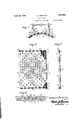
in the accompanying drawings Figure l is edge elevation of the pad constructed in accordance with the invention showing the heating element associated therewith.
JFigure 2 is a plan view of the pad. VJ`igure 3 is an edge elevation looking toward one longer edge of said pad.
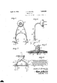
Figure l is an enlarged fragmentary sectional view on the line of Figure l looking in the direction of the arrows.
.Figure 5 is an elevation of the heating element.
Figure 6 is side elevation thereof.
Figure is a plan view.
Figure 8 is an enlarged fragmentary sectional view on the line 8 8 of Figure 5.
Figure 9 is a detail plan view of one of the heating units removed from its housing showing the insulation block or plate.
Similar reference characters indicate corresponding parts throughout the several views in the drawings.
Referring to the drawings in detail, the pad comprises a flexible or bendable metallic body A which may be of any desirable size and preferably of rectangular shape and includes plurality of links l0, each formed with a. flattened face ll and a corrugated opposite face l2 with rounded ends 13. These links l0 are preferably of the shape as shown in Figure lof the drawings and are held in staggered relation to each other in parallel rows in the assembly of the pad by threading through their openings or holes la therein a flexible wire or other metallic member l5, it being preferable to have the wire made up of a plurality of twisted strands of comparatively thin wires. The links l0 have in association therewith at opposite longer edges only filler links 16 which are alternately arranged along the said longer edges of the pad so as to present a smooth flush edging to the 9 pad at the longer sides thereof.
The wire l5 is provided at each end with a suitable anchoring terminal 17 in this instance being in the form of a notch made from said wire although it may be otherwise jfinger fitted with a retaining terminal. The wire 15 provides aI pivotal connection between links adjacent each other of the plurality of rows thereof, so that the pad in its entirety may be readily flexed or bent to closely engage the piece of work or the surface of a tire on the application of the pad thereto for vulcanizing of the same. The links 10 in their arrangement are given sufficient play so that each row of links may be moved relatively to its adjacent row, thus augmenting the bending or flexing of the pad in a direction transverse to the tire, suflicient flexibility being provided to bend or flex the pad circumferentially of the said tire.
The pad A in its entirety is especially useful in vulcanizing a tire when the pad must extend partially upon the tread and partially along one side wall of the same and it will closely engage the face or surface of the tire irrespective of the location of the part or portion thereof to be vulcanized.
Associated with the pad A to apply heat thereto and for the distribution of such heat throughout the entire pad body there is a heating element, which comprises a pair of elongated flat faced shoes 1S, each in the form of a housing inclosing a heating coil or unit 19, the latter being carried by an insulation plate 20 which is arranged lengthwise in the housing and incased by an insulating lining or packing 21 preferably asbestos, the latter being confined by the housing.
The heating units or coils 19 are adapted to be included in a circuit with a source of current and for this purpose are connected in their pair with conductors 22 and 23 respectively, the latter being of any suitable length and having associated therewith a socket plug 24 insertable in a switch socket of the current source of supply. The conductors 22 and 23 are trained through insulation thimbles 25 mounted on the housing 21 medially thereof and these thimbles constitute holds for the manual engagement of the heating element with the pad in a manner presently described.
The conductors 22 and 23 not only provide for the passage of electric current but also provide a flexible connection between the elongated shoes 18. By flexibility these shoes 18 may be spaced apart at the option of the user of the pad so as to apply heat at spaced points thereof and the heat from said shoes will be distributed throughout the links 10 and the metallic member 15, which latter will carry the heat from one link to the other as should be obvious.
Determined links 10 of the pad A and preferably throughout a major portion of the latter in the sides 12 thereof are provided with female substantially ball-shaped sockets 26, while formed on the shoe centrally thereof are substantially ball-shaped male fastening mediums 27, these being adapted for frictional engagement in the sockets 26 for the detachable securing of the shoes with selected links 1()` of the pad A and thus in this manner the heating element will be detachably held fast about the pad at determined localities thereon, thus in this manner the heat may be localized accordingly to the work to be treated.
It will be apparent that the heating element including the pair of shoes may be arranged in proper contact with the pad where the latter is placed partially upon the tread and partially upon the side wall of a tire. The shoes 18 may be arranged either longitudinally or transversely with respect to t e pad A and in engagement a unitary structure is presented.
'What is claimed is 1. A heating pad comprising a plurality of pivotally connected links arranged in close parallel rows, certain of said links having sockets therein, and an electric heating element having a shoe provided with a fastening medium for detachably engaging in the socket without retarding flexibility of the links in their pivotal association with each other.
2. A heating pad comprising a plurality of pivotally connected links arranged in close parallel rows, certain of said links having sockets therein, an electric heating element having a shoe provided with a fastening Inedium for detachably engaging in the socket without retarding flexibility of the links in their pivotal association with each other, and flexible means for the shoe and constituting a source of current supply thereto.
3. ln a heating pad, a bendable metallic body having free flexibility, an electric heating shoe for association with the body, and means on the heating devices for detachably coicilpling the same at elected localities on the bo y.
4. ln a heating pad, a bendable metallic body having free iexibility, electric heating devices for association with the body, and means on the heating devices for detachably connecting the same at elected localities on the body, said heating devices including a plurality of flexibly connected shoes.
5. In a heating pad, a bendable metallic body having free iexibility, electric heating devices for association with the body, means on the heating devices for detachably connecting the same at elected localities on the body, said heating devices including a plurality of flexibly connected shoes, and means for detachably arranging the shoes in an electric current supply.
In testimony whereof I affix my signature.
JAMES H. BROWNE.
Priority Applications (1)
| Application Number | Priority Date | Filing Date | Title |
|---|---|---|---|
| US550803A US1855092A (en) | 1931-07-14 | 1931-07-14 | Heating pad |
Applications Claiming Priority (1)
| Application Number | Priority Date | Filing Date | Title |
|---|---|---|---|
| US550803A US1855092A (en) | 1931-07-14 | 1931-07-14 | Heating pad |
Publications (1)
| Publication Number | Publication Date |
|---|---|
| US1855092A true US1855092A (en) | 1932-04-19 |
Family
ID=24198624
Family Applications (1)
| Application Number | Title | Priority Date | Filing Date |
|---|---|---|---|
| US550803A Expired - Lifetime US1855092A (en) | 1931-07-14 | 1931-07-14 | Heating pad |
Country Status (1)
| Country | Link |
|---|---|
| US (1) | US1855092A (en) |
Cited By (9)
| Publication number | Priority date | Publication date | Assignee | Title |
|---|---|---|---|---|
| US2607876A (en) * | 1949-10-31 | 1952-08-19 | Richard L Bergen | Electric heating device |
| US2722597A (en) * | 1955-01-19 | 1955-11-01 | Leonard E Steiner | Articulated electric heating mat |
| US4144445A (en) * | 1977-12-27 | 1979-03-13 | Emerson Electric Co. | Open coil electric heaters |
| US4255649A (en) * | 1978-09-29 | 1981-03-10 | Joseph Fisher | Flexible heating elements |
| US4565921A (en) * | 1983-03-17 | 1986-01-21 | Gaetano Piazzola | Electric thermal unit for controllably heating cylinders having two coaxial interspaces for circulating ventilation air therethrough |
| US4613744A (en) * | 1983-08-02 | 1986-09-23 | Refurbished Turbine Components Limited | Methods of repair |
| US4628191A (en) * | 1983-03-17 | 1986-12-09 | Gaetano Piazzola | Electric thermal unit |
| US5221827A (en) * | 1992-02-12 | 1993-06-22 | Shell Oil Company | Heater blanket for in-situ soil heating |
| US5306897A (en) * | 1991-06-25 | 1994-04-26 | Turbine Blading Limited | Heat treatment method and apparatus for turbine blades using flexible heater sleeve |
-
1931
- 1931-07-14 US US550803A patent/US1855092A/en not_active Expired - Lifetime
Cited By (10)
| Publication number | Priority date | Publication date | Assignee | Title |
|---|---|---|---|---|
| US2607876A (en) * | 1949-10-31 | 1952-08-19 | Richard L Bergen | Electric heating device |
| US2722597A (en) * | 1955-01-19 | 1955-11-01 | Leonard E Steiner | Articulated electric heating mat |
| US4144445A (en) * | 1977-12-27 | 1979-03-13 | Emerson Electric Co. | Open coil electric heaters |
| US4255649A (en) * | 1978-09-29 | 1981-03-10 | Joseph Fisher | Flexible heating elements |
| US4320253A (en) * | 1978-09-29 | 1982-03-16 | Joseph Fisher | Ceramic beads for heaters |
| US4565921A (en) * | 1983-03-17 | 1986-01-21 | Gaetano Piazzola | Electric thermal unit for controllably heating cylinders having two coaxial interspaces for circulating ventilation air therethrough |
| US4628191A (en) * | 1983-03-17 | 1986-12-09 | Gaetano Piazzola | Electric thermal unit |
| US4613744A (en) * | 1983-08-02 | 1986-09-23 | Refurbished Turbine Components Limited | Methods of repair |
| US5306897A (en) * | 1991-06-25 | 1994-04-26 | Turbine Blading Limited | Heat treatment method and apparatus for turbine blades using flexible heater sleeve |
| US5221827A (en) * | 1992-02-12 | 1993-06-22 | Shell Oil Company | Heater blanket for in-situ soil heating |
Similar Documents
| Publication | Publication Date | Title |
|---|---|---|
| US1855092A (en) | Heating pad | |
| US1384467A (en) | Bandage | |
| US1539299A (en) | Electrotherapeutic massage appliance | |
| US2339409A (en) | Electrically heated shoulder pad | |
| US1594053A (en) | Electrically-heated appliance for use upon the body | |
| US2712591A (en) | Electrical bandage | |
| US1975518A (en) | Electrode means for therapeutic purposes | |
| US2255376A (en) | Electrical heating unit and pad | |
| US2419655A (en) | Electric heater | |
| US2018512A (en) | Electric heating pad | |
| US3428993A (en) | Electrically heated windshield wiper assembly | |
| US2481181A (en) | Electrical connector apparatus | |
| US1364971A (en) | Brush | |
| US1944390A (en) | Electrical conductor | |
| US2666839A (en) | Electric heating pad | |
| JP2008103317A (en) | Light emitting diode lighting device and power supply device used for the lighting device | |
| US2801323A (en) | Flexible hoses | |
| US2022519A (en) | Method of making electric heating pads | |
| US1785638A (en) | Hose coupling | |
| US1583884A (en) | Attachment plug for electric heating devices | |
| US1701973A (en) | Electric foot warmer | |
| US1415784A (en) | Electrical body heater and steamer | |
| US1125889A (en) | Electrically-heated steering-rim. | |
| US1624397A (en) | Electromagnetic therapeutic-compress-heating appliance | |
| US1543828A (en) | Combined shoe tree and drier |