US1855091A - Clod crusher and soil pulverizer - Google Patents
Clod crusher and soil pulverizer Download PDFInfo
- Publication number
- US1855091A US1855091A US560639A US56063931A US1855091A US 1855091 A US1855091 A US 1855091A US 560639 A US560639 A US 560639A US 56063931 A US56063931 A US 56063931A US 1855091 A US1855091 A US 1855091A
- Authority
- US
- United States
- Prior art keywords
- soil
- shaft
- bars
- head members
- recesses
- Prior art date
- Legal status (The legal status is an assumption and is not a legal conclusion. Google has not performed a legal analysis and makes no representation as to the accuracy of the status listed.)
- Expired - Lifetime
Links
- 239000002689 soil Substances 0.000 title description 21
- 241000239290 Araneae Species 0.000 description 9
- 230000000149 penetrating effect Effects 0.000 description 2
- 241001247248 Aclodes Species 0.000 description 1
- 235000016068 Berberis vulgaris Nutrition 0.000 description 1
- 241000335053 Beta vulgaris Species 0.000 description 1
- 230000003292 diminished effect Effects 0.000 description 1
- 230000003467 diminishing effect Effects 0.000 description 1
- 239000002362 mulch Substances 0.000 description 1
- 230000002093 peripheral effect Effects 0.000 description 1
- 238000010298 pulverizing process Methods 0.000 description 1
- 230000000979 retarding effect Effects 0.000 description 1
- 239000004576 sand Substances 0.000 description 1
Images

Classifications
-
- A—HUMAN NECESSITIES
- A01—AGRICULTURE; FORESTRY; ANIMAL HUSBANDRY; HUNTING; TRAPPING; FISHING
- A01B—SOIL WORKING IN AGRICULTURE OR FORESTRY; PARTS, DETAILS, OR ACCESSORIES OF AGRICULTURAL MACHINES OR IMPLEMENTS, IN GENERAL
- A01B29/00—Rollers
- A01B29/04—Rollers with non-smooth surface formed of rotatably-mounted rings or discs or with projections or ribs on the roller body; Land packers
Definitions
- This invention relates to a combined clod crusher and soil pulverizer especially adapted to be attached to the frame of a cultivator and it consists in the novel features hereinafter described and claimed.
- An object of the invention is to provide an attachment of the character indicated which is of simple and durable structure and including bearing arms adapted to be applied in to the frame of the cultivator and having at their lower ends bearing recesses adapted to receive head members which are journaled therein.
- the ends of a shaft are adjustably fixed to said head members and at intervals along the shaft spiders are mounted and upon the peripheries of said spiders crushing and pulverizing bars are mounted.
- Soil penetrating teeth are mounted upon said bars and are adapted to enter the surface of the soil and break any crust that may occur at the surface area of the soil.
- Means are provided at the intermediate portion of the said shaft for retarding the turning movement thereof in order that the said teeth may be caused to drag in the soil and thereby mulch the same.
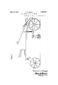
- FIG. 1 is a side elevational view of a cultivator frame with the clod crusher and soil pulverizer attached thereto.
- Figure '2 is a side elevational View of the clod crusher and soil pulverizer.
- Figure 3 is an end view of the same.
- Figure 4 is a longitudinal sectional view of the same cut on the line 4-4 of Figure 3
- 40 and Figure 5 is a transverse sectional view of the same cut on the line 55 of Figure 2.
- the frame of the cultivator to which the 4 attachment is applied may be of any design or pattern such as -is usuallyf applied.
- the attachment include-s arms-1 which are secured at their" upperends to the frame of the cultivator by means of clamp devices 2 or other suitable attaching means.
- the arms 1 are provided at their lower ends with recesses 2 which receive head members 3, the said'head members being journaled for ro tation in thesaidrecesses.
- the edges of therecesses 2 extend down along the sides'of the head members?) as shown in Figure 4 of the drawings so that the said head inem-bersmay not become dislodged fromthe recesses after they have been properly positionedtherein
- Sections 4' are appliedjtor thelovver ends of the'arms 1 and the said sections are provided with curved inner surfaces which receive the lower portions of the head members 3 and whereby the.
- Spider -membersw5 are mounted upon a. shaft 6v at intervals: and the ends of they said shaft are screwed into the centers of the head members 3.
- Pins. 7 pass through the ends of the shaft 6 and bear against the outervsurfaces of the' head' members 3 and prevent the shaft from unscrewing fromthe head members:
- Longitudinally disposed bars 8 are mounted upon theperipheries of the spiders 5 andthe-saidbars are disposed approximately parallel with relation to' each other..
- An arm 12 is secured at'its upperl endto the frame of the cultivatorand is provided at its lower end with a casing chamber.;13.
- a brake shoe 14 is housed in the chamber 13 and isiprovided with, an inner cone shaped surface 15 which bears in a groove provided in the periphery of a disk 16 mounted upon the intermediate portion of the shaft 6.
- a section 17 receives the lower portion of the brake shoe 14:, the section 17 is provided at its ends and at its outer sides with lugs 18 and similar lugs 19 are mounted upon the lower end of the arm 5.
- Bolts 20 pass through the lugs 18 and 19 and have nuts 21 screwed upon their upper ends.
- Springs 22 are interposed between the nuts 21 and the lugs 19 and by tightening the nuts 21 upon the bolts 20.the springs 22 are compressed whereby the frictional contact between the shoe 14 and the periphery of the disk 16 may be increased or diminished asdesired.
- the operation of the device is as followsi '7 i
- the teeth or spikes 9 upon the lower bars penetrate the-surface of'theT soil and thus the spiders are made to rotate with the shaft 6 and as the teeth come in contact with the crust of the soil the crust is broken, mulched, and the clods are crushed and pulverized by the teeth and the bars.
- the shoe 14 may be brought into tight frictional contact with the peripheral groove of V the disk 16 and thus the rotation of the shaft and the parts carried thereby maybe retarded so that the teeth will drag through the soil and thoroughly break the same.
- Aclod crusher and soil pulverizer attachment comprising arms provided at their lower ends with hearing recesses, head members journaled in said recesses, a shaft fixed to the head members, spiders mounted upon housed within the casing chamber, a disk mounted upon the shaft and engaged by the brake shoe, lugs provided at the lower end of the said arm and the upper end of said section, bolts passing through said lugs, nuts screwed upon the bolts and springs interposed between the nuts and certain of the said lugs.
- a clod crusher and soil pulverizer attachment comprising arms provided at'their lower ends with hearing recesses, head meII bers 'journaled in said recesses, a shaft fixed I to the head members, spiders mounted upon the shaft, bars mounted upon'the peripheries ofthe spiders,'spike teeth carried by the bars, an arm adapted to be applied to a cultivator and provided at its lower end witha chamber, said shaft passingthrough said chamber, a brake shoe'located in the chamber and a disk mounted upon the shaft and engaging said brake shoe and means for increasing or diminishing the frictional contact between the brake shoe and the disk.
- a clod crusher and soil pulverizer attachment comprising arms provided at their lower ends with recesses, head members j ournale'd in said recesses, a shaft-fixed to the
Landscapes
- Life Sciences & Earth Sciences (AREA)
- Engineering & Computer Science (AREA)
- Mechanical Engineering (AREA)
- Soil Sciences (AREA)
- Environmental Sciences (AREA)
- Soil Working Implements (AREA)
Description
April 19, 1932. P. w. BROWN I CLOD CRUSHER AND SOIL PULVERIZER 2 Sheets-Sheet 1 Filed Sept. 1, 1951 Farsan M Bra aw? INVENTOR d/nda; "T
April 19, 1932. p BROWN 1,855,091'
CLOD CRUSHERAND SOIL PULVER-IZER Filed Sept. 1, 19:5 2 sheets-sheet 2 51B w R 3H 0 Q) II!B o a flak ma *0 3 on 1 ma 1 k "x Q R Parse)? Mfirozwr 1% INVENTOR ATTORNEY Patented Apr. 19, 1932 UNITED STATES rAn'soN w. BROWN, or LINGLE, WYOMING oLon CRUSHER AND SOIL rurivnmznn Application filed September 1, 1931. Serial'mn. 560,639;
This invention relates to a combined clod crusher and soil pulverizer especially adapted to be attached to the frame of a cultivator and it consists in the novel features hereinafter described and claimed.
An object of the invention is to provide an attachment of the character indicated which is of simple and durable structure and including bearing arms adapted to be applied in to the frame of the cultivator and having at their lower ends bearing recesses adapted to receive head members which are journaled therein. The ends of a shaft are adjustably fixed to said head members and at intervals along the shaft spiders are mounted and upon the peripheries of said spiders crushing and pulverizing bars are mounted.
Soil penetrating teeth are mounted upon said bars and are adapted to enter the surface of the soil and break any crust that may occur at the surface area of the soil. Means are provided at the intermediate portion of the said shaft for retarding the turning movement thereof in order that the said teeth may be caused to drag in the soil and thereby mulch the same. When the bars come in contact with the surface of the soil the clods are crushed and the soil is pulverized at the surface.
In the accompanying drawings Figure 1 is a side elevational view of a cultivator frame with the clod crusher and soil pulverizer attached thereto.
Figure '2 is a side elevational View of the clod crusher and soil pulverizer.
Figure 3 is an end view of the same.
Figure 4 is a longitudinal sectional view of the same cut on the line 4-4 of Figure 3, 40 and Figure 5 is a transverse sectional view of the same cut on the line 55 of Figure 2.
As illustrated in the accompanying drawings the frame of the cultivator to which the 4 attachment is applied may be of any design or pattern such as -is usuallyf applied. for
cultivating crops as beets. V The attachment include-s arms-1 which are secured at their" upperends to the frame of the cultivator by means of clamp devices 2 or other suitable attaching means. The arms 1 are provided at their lower ends with recesses 2 which receive head members 3, the said'head members being journaled for ro tation in thesaidrecesses. The edges of therecesses 2 extend down along the sides'of the head members?) as shown in Figure 4 of the drawings so that the said head inem-bersmay not become dislodged fromthe recesses after they have been properly positionedtherein Sections 4' are appliedjtor thelovver ends of the'arms 1 and the said sections are provided with curved inner surfaces which receive the lower portions of the head members 3 and whereby the. upper portionsof the peripheries'of the head members are held in the recesses 2. Spider -membersw5 are mounted upon a. shaft 6v at intervals: and the ends of they said shaft are screwed into the centers of the head members 3. Pins. 7 pass through the ends of the shaft 6 and bear against the outervsurfaces of the' head' members 3 and prevent the shaft from unscrewing fromthe head members: Longitudinally disposed bars 8 are mounted upon theperipheries of the spiders 5 andthe-saidbars are disposed approximately parallel with relation to' each other.. 'Soil penetrating spikes 9 are screwed into the bars Sand lock nuts 10 are 'screwed'upon'the spikes 9 and bear attheir inner surfacesagainst the outer surfaces of the bars and securely lock the spikes-in position upon the bars; The outer ends of the spikes 9 are squared as at 11.
An arm 12 is secured at'its upperl endto the frame of the cultivatorand is provided at its lower end with a casing chamber.;13. A brake shoe 14 is housed in the chamber 13 and isiprovided with, an inner cone shaped surface 15 which bears in a groove provided in the periphery of a disk 16 mounted upon the intermediate portion of the shaft 6. A section 17 receives the lower portion of the brake shoe 14:, the section 17 is provided at its ends and at its outer sides with lugs 18 and similar lugs 19 are mounted upon the lower end of the arm 5. Bolts 20 pass through the lugs 18 and 19 and have nuts 21 screwed upon their upper ends. Springs 22 are interposed between the nuts 21 and the lugs 19 and by tightening the nuts 21 upon the bolts 20.the springs 22 are compressed whereby the frictional contact between the shoe 14 and the periphery of the disk 16 may be increased or diminished asdesired.
The operation of the device is as followsi '7 i As the cultivator frame is passed 'over the surface of the soil the teeth or spikes 9 upon the lower bars penetrate the-surface of'theT soil and thus the spiders are made to rotate with the shaft 6 and as the teeth come in contact with the crust of the soil the crust is broken, mulched, and the clods are crushed and pulverized by the teeth and the bars. By tightening the bolts 21 upon the nuts 20 the shoe 14 may be brought into tight frictional contact with the peripheral groove of V the disk 16 and thus the rotation of the shaft and the parts carried thereby maybe retarded so that the teeth will drag through the soil and thoroughly break the same.
Having described the invention what is claimed is:
1. Aclod crusher and soil pulverizer attachment comprising arms provided at their lower ends with hearing recesses, head members journaled in said recesses, a shaft fixed to the head members, spiders mounted upon housed within the casing chamber, a disk mounted upon the shaft and engaged by the brake shoe, lugs provided at the lower end of the said arm and the upper end of said section, bolts passing through said lugs, nuts screwed upon the bolts and springs interposed between the nuts and certain of the said lugs.
In testimony whereof I afiix my signature.
PARSON W. BROWN. 1
the shaft, bars mounted upon the peripheries of the'spiders, spike'teeth carried by the bars, an armadapted to be applied to a cultivator andpr'ovided at its lower end with a chamber, said shaftpassing through said chamber, a brake shoe located in the chamber and a disk mounted'upon the shaft and engaging said brake shoe. r
2. A clod crusher and soil pulverizer attachment comprising arms provided at'their lower ends with hearing recesses, head meII bers 'journaled in said recesses, a shaft fixed I to the head members, spiders mounted upon the shaft, bars mounted upon'the peripheries ofthe spiders,'spike teeth carried by the bars, an arm adapted to be applied to a cultivator and provided at its lower end witha chamber, said shaft passingthrough said chamber, a brake shoe'located in the chamber and a disk mounted upon the shaft and engaging said brake shoe and means for increasing or diminishing the frictional contact between the brake shoe and the disk. r I
3. A clod crusher and soil pulverizer attachment comprising arms provided at their lower ends with recesses, head members j ournale'd in said recesses, a shaft-fixed to the
Priority Applications (1)
| Application Number | Priority Date | Filing Date | Title |
|---|---|---|---|
| US560639A US1855091A (en) | 1931-09-01 | 1931-09-01 | Clod crusher and soil pulverizer |
Applications Claiming Priority (1)
| Application Number | Priority Date | Filing Date | Title |
|---|---|---|---|
| US560639A US1855091A (en) | 1931-09-01 | 1931-09-01 | Clod crusher and soil pulverizer |
Publications (1)
| Publication Number | Publication Date |
|---|---|
| US1855091A true US1855091A (en) | 1932-04-19 |
Family
ID=24238659
Family Applications (1)
| Application Number | Title | Priority Date | Filing Date |
|---|---|---|---|
| US560639A Expired - Lifetime US1855091A (en) | 1931-09-01 | 1931-09-01 | Clod crusher and soil pulverizer |
Country Status (1)
| Country | Link |
|---|---|
| US (1) | US1855091A (en) |
Cited By (2)
| Publication number | Priority date | Publication date | Assignee | Title |
|---|---|---|---|---|
| USD943643S1 (en) * | 2020-10-01 | 2022-02-15 | Marlon Lane Curtis | Grouser cage for compacting and preparation of soil and seeding apparatus |
| US11350553B2 (en) * | 2020-08-26 | 2022-06-07 | Marlon Lane Curtis | Grouser-cage attachment for equipment |
-
1931
- 1931-09-01 US US560639A patent/US1855091A/en not_active Expired - Lifetime
Cited By (2)
| Publication number | Priority date | Publication date | Assignee | Title |
|---|---|---|---|---|
| US11350553B2 (en) * | 2020-08-26 | 2022-06-07 | Marlon Lane Curtis | Grouser-cage attachment for equipment |
| USD943643S1 (en) * | 2020-10-01 | 2022-02-15 | Marlon Lane Curtis | Grouser cage for compacting and preparation of soil and seeding apparatus |
Similar Documents
| Publication | Publication Date | Title |
|---|---|---|
| US2773343A (en) | Cooperating rotatable disk type beet harvester | |
| US2505276A (en) | Harrow attachment for tractor wheels | |
| US2664040A (en) | Rotary earth tilling device | |
| US2066610A (en) | Farm machinery | |
| US1855091A (en) | Clod crusher and soil pulverizer | |
| US2808771A (en) | Rolling spiral cultivator | |
| US2749827A (en) | Soil conditioner | |
| DE440230C (en) | Soil culture device with rotating cultivator tine drum | |
| US3375879A (en) | Soil pulverizing unit | |
| US2035591A (en) | Combined harrow and pulverizer | |
| US1769601A (en) | Multiple disk for soil pulverizers | |
| US2128077A (en) | Rotary cultivator | |
| DE527579C (en) | Soil cultivation machine with rotating tools | |
| US2725807A (en) | Rotary harrow | |
| US337480A (en) | Roller-cultivator | |
| US1805865A (en) | Cultivator attachment | |
| US843460A (en) | Cotton-chopper. | |
| US1490514A (en) | Harrow | |
| US1197086A (en) | Agricultural implement. | |
| GB314326A (en) | ||
| US1650400A (en) | Dirt conditioner | |
| US1443222A (en) | Farm implement | |
| US1699152A (en) | Rotary earth-working element | |
| US1703539A (en) | Soil-pulverizing machine | |
| US1357905A (en) | Ground-mulshing and insect-displacing drag |