US1855083A - Control for dirigible headlights - Google Patents
Control for dirigible headlights Download PDFInfo
- Publication number
- US1855083A US1855083A US540463A US54046331A US1855083A US 1855083 A US1855083 A US 1855083A US 540463 A US540463 A US 540463A US 54046331 A US54046331 A US 54046331A US 1855083 A US1855083 A US 1855083A
- Authority
- US
- United States
- Prior art keywords
- link
- lights
- fender
- headlights
- steering mechanism
- Prior art date
- Legal status (The legal status is an assumption and is not a legal conclusion. Google has not performed a legal analysis and makes no representation as to the accuracy of the status listed.)
- Expired - Lifetime
Links
- 101100021281 Caenorhabditis elegans lin-8 gene Proteins 0.000 description 1
- 238000010276 construction Methods 0.000 description 1
- 238000005553 drilling Methods 0.000 description 1
- 230000037431 insertion Effects 0.000 description 1
- 238000003780 insertion Methods 0.000 description 1
- 239000000463 material Substances 0.000 description 1
- 230000013011 mating Effects 0.000 description 1
- 239000007769 metal material Substances 0.000 description 1
- IDOWTHOLJBTAFI-UHFFFAOYSA-N phenmedipham Chemical compound COC(=O)NC1=CC=CC(OC(=O)NC=2C=C(C)C=CC=2)=C1 IDOWTHOLJBTAFI-UHFFFAOYSA-N 0.000 description 1
Images

Classifications
-
- B—PERFORMING OPERATIONS; TRANSPORTING
- B60—VEHICLES IN GENERAL
- B60Q—ARRANGEMENT OF SIGNALLING OR LIGHTING DEVICES, THE MOUNTING OR SUPPORTING THEREOF OR CIRCUITS THEREFOR, FOR VEHICLES IN GENERAL
- B60Q1/00—Arrangement of optical signalling or lighting devices, the mounting or supporting thereof or circuits therefor
- B60Q1/02—Arrangement of optical signalling or lighting devices, the mounting or supporting thereof or circuits therefor the devices being primarily intended to illuminate the way ahead or to illuminate other areas of way or environments
- B60Q1/04—Arrangement of optical signalling or lighting devices, the mounting or supporting thereof or circuits therefor the devices being primarily intended to illuminate the way ahead or to illuminate other areas of way or environments the devices being headlights
- B60Q1/06—Arrangement of optical signalling or lighting devices, the mounting or supporting thereof or circuits therefor the devices being primarily intended to illuminate the way ahead or to illuminate other areas of way or environments the devices being headlights adjustable, e.g. remotely-controlled from inside vehicle
- B60Q1/08—Arrangement of optical signalling or lighting devices, the mounting or supporting thereof or circuits therefor the devices being primarily intended to illuminate the way ahead or to illuminate other areas of way or environments the devices being headlights adjustable, e.g. remotely-controlled from inside vehicle automatically
- B60Q1/12—Arrangement of optical signalling or lighting devices, the mounting or supporting thereof or circuits therefor the devices being primarily intended to illuminate the way ahead or to illuminate other areas of way or environments the devices being headlights adjustable, e.g. remotely-controlled from inside vehicle automatically due to steering position
- B60Q1/124—Arrangement of optical signalling or lighting devices, the mounting or supporting thereof or circuits therefor the devices being primarily intended to illuminate the way ahead or to illuminate other areas of way or environments the devices being headlights adjustable, e.g. remotely-controlled from inside vehicle automatically due to steering position by mechanical means
Definitions
- My invention relates to controls for dirigible headlights for automobiles or other vehicles of the type which are controlled by the g steering mechanism in such a manner that the lights are turned in the direction in which the automobile is turning.
- the primary object of my invention is to provide a novel and improved mechanism of this type.
- Another object ofthe invention is to provide a system of levers which can be applied to the ordinary car with little difficulty and without changing the location of the lights.
- a further object ofthe inven- W tion is to provide a novel arrangement of levers and links connecting the steering mechanism with one of the lights, one of these links or levers extending through an opening in the fender and being fulcrumed in
- a further obj ect is to provide 21) means for connecting the two lights for joint movement, these means extending in front of the lights so that thelocation of the lights need not be changed and so that the lines of the car will not be destroyed.
- Final- "aa ly it is an object of my invention to provide a simple and effective mounting to permit the turning of the lights which can be substituted very easily for the ordinary fixed mounting.
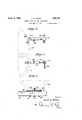
- Fig. 1 is a side elevation of my control means, the automobile being shown in broken lines.
- Fig. 2 is a front elevation of the same.
- Fig. 3 is a top plan View of the headlights and the connection therebetween.
- Fig. 4 is a detail cross section of the fulcrum for the intermediate link.
- Fig. 5 is a top plan view of a detail.
- Fig. 6 is a rear elevation of the same.
- Fig.7 is a front elevation of the mounting of one of the lights. 1
- FIG. 1 The drawings show an automobile 2 having a fender 4, wheels 6 and a; steering mechanism including a'drag link 8 which connects the steering shaft to the front wheels.
- steering mechanism including a'drag link 8 which connects the steering shaft to the front wheels.
- cross-bar or rod 10 in the frontofthe 'automobile'o'n which are mounted headlights 12in a manner to be described below.
- arod 14 having a triangular bracing portion 16 integral therewith.
- a split clamp 18 the parts of which areseoured together by bolts may be used for holding the end of the rod 14 rigidly in place.
- a ball and socket joint 20 is provided, connecting this rod with an upright link or lever 22 for universal movement therebetween.
- the lever 22 extends through ahole 24 in the fender 4 and is fulcrumed therein.
- the hole 24 is provided with a'washer 26 of fibrous or other non-metallic material to pre vent the lever 22 from rattling in the hole.
- the upper end of the lever 22 is provided with a second ball and socket joint 28 to which is connected a substantially horizontal link member 30.
- This link member30 as shownin Figs. 5 and 6, is composed of two parts 32 and 34, hinged together by a horizontal pivot '36.
- the member 34 is rigidly secured to one side of one of the lightsl2.
- the lights 12 must be joined together for common movement. Rigidly secured to the innerside surface of each of the headlights is an arm 38, extending'forwardly of the lights; The two arms 38 are connected by a link 40 pivoted at 41, 41 to the outer or forward ends of the two arms. i Fig. 7 shows in detail the'mountingfor the lights.
- On the usual cross rod 10 is placed a pair of opposed discs 42, 44,theset discs having oppositely directed circumferential grooves 46 in their mating faces, and ball' bearings 48 in these grooves.
- the upper disc 42 is secured to the light, while disc 44 is secured to the rod 10 by bolts 45.
- a bolt 50 extends upwardly through the rod 10 and through the centers of the two plates, and the upper end of the bolt is engaged by nuts 52, 54 which engage the inner side ofthe lights and hold it in position on the rod 10. In this way, free rotation of the lights is permitted, without changing their position on the vehicle.
- the link or lever 22 is preferably formed in two sections, connected by a turnbuckle 56. This permits insertion through the fender, and also allows some adjustment of the parts.
- a headlight mounted to turn about a vertical axis, a link connected to said light, a lever connected to said link and fulcrumed in said fender, and a second link connected to saidleverand to the steering .said light.
- said fender having an aperture therein, an annular member of non-metalllc material; within said aperture and covering the edges thereof, a pair of headlights mounted to turn about verticalaxes, a link secured to one of said lights, a second link pivoted to said first link and fulcrumed in said annular member, a memberfixed on said drag link and pivoted to saidsecond link, and means connecting said lights to cause them to move together,-whereby movement of the steering mechanism to turn the vehicle also turns said lights.
- a pair of headlights mounted to turn about vertical axes,'means connecting said lightsto cause them to move together, a link connected to one of said lightsvincluding two parts hinged together on'a horizontal pivot, a second link pivoted to said first link and fulcrumed in-said fen der, a thirdlinkpivoted to said second link and connected to said steering mechanism, whereby movement of the steering mechanism toturn the vehicle also turns said lights, said first link serving to permit relative vertical movement between said steering mechanism and said lights.
- a steering mechanism including a drag link, a rod extending across the front thereof, and a pair of headlights
- that improvement which comprises a disc mounted onsaid rod, other discsfsecured to ture and covering the edges thereof, a link connected to one of said lights including two parts hinged together on a horizontal pivot, a second link pivoted to said first link and fulcrumed in said annular member, and a member pivoted to said second link and rigidly secured to said drag link, whereby movement of said steering mechanism to turn the vehicle also turns said lights.
- a vehicle having a steering mechanism and a fender, a headlight mounted to turn about a vertical axis, a lever fulcrumed in said fender, and means pivotally connecting said lever to said headlight and to said steering mechanism, whereby movement of the mechanism to turn the vehicle also turns said light.
- a headlight mounted to turn about a vertical axis, a lever extending through said fender and having a fulcrum supported by said fender, and means pivotally connecting said lever to said headlight and to said steering mechanism, whereby movement of the mechanism to turn the vehicle also turns said light.
Landscapes
- Engineering & Computer Science (AREA)
- Mechanical Engineering (AREA)
- Lighting Device Outwards From Vehicle And Optical Signal (AREA)
Description
April 19, 1932.
v J. A. YOUNG CONTROL FOR DIRIGIBLE HEADLIGHTS Filed May 27, 1931 2 sheets-Sheet.
April 19, 1932. J. A. YOUNG 1,855.083
CONTROL FOR IRIGIBLE HEAQLIGHTS Filed May 27, 1931 2 Sheets- Sheet 2 gwwntov Jesse A. Youn I this opening.
Patented Apr. 19, 1932 UNITED STATES JESSE A. YOUNG, OF CLARKSVILLE, TENNESSEE CONTROL FOB DIRIGIBLE HEADLIGHTS Application filed May 27, 1931. Serial No. 540,468.
My invention relates to controls for dirigible headlights for automobiles or other vehicles of the type which are controlled by the g steering mechanism in such a manner that the lights are turned in the direction in which the automobile is turning. p
The primary object of my invention is to provide a novel and improved mechanism of this type. Another object ofthe invention is to provide a system of levers which can be applied to the ordinary car with little difficulty and without changing the location of the lights. A further object ofthe inven- W tion is to provide a novel arrangement of levers and links connecting the steering mechanism with one of the lights, one of these links or levers extending through an opening in the fender and being fulcrumed in A further obj ect is to provide 21) means for connecting the two lights for joint movement, these means extending in front of the lights so that thelocation of the lights need not be changed and so that the lines of the car will not be destroyed. Final- "aa ly, it is an object of my invention to provide a simple and effective mounting to permit the turning of the lights which can be substituted very easily for the ordinary fixed mounting. v
Other objects and advantages of the invention will be apparent from the following description when taken in conjunction with the accompanying drawings which form a part thereof.
In the drawings:
Fig. 1 is a side elevation of my control means, the automobile being shown in broken lines.
Fig. 2 is a front elevation of the same.
Fig. 3 is a top plan View of the headlights and the connection therebetween.
Fig. 4 is a detail cross section of the fulcrum for the intermediate link.
Fig. 5 is a top plan view of a detail.
Fig. 6 is a rear elevation of the same.
Fig.7 is a front elevation of the mounting of one of the lights. 1
The drawings show an automobile 2 having a fender 4, wheels 6 and a; steering mechanism including a'drag link 8 which connects the steering shaft to the front wheels. In addition, there is the usual cross-bar or rod 10 in the frontofthe 'automobile'o'n which are mounted headlights 12in a manner to be described below. v i
Rigidly attached to the drag link 8 is arod 14 having a triangular bracing portion 16 integral therewith. A split clamp 18 the parts of which areseoured together by bolts may be used for holding the end of the rod 14 rigidly in place. At the free end of the rod 14 a ball and socket joint 20 is provided, connecting this rod with an upright link or lever 22 for universal movement therebetween. The lever 22 extends through ahole 24 in the fender 4 and is fulcrumed therein. The hole 24 is provided with a'washer 26 of fibrous or other non-metallic material to pre vent the lever 22 from rattling in the hole. The upper end of the lever 22 is provided with a second ball and socket joint 28 to which is connected a substantially horizontal link member 30. This link member30, as shownin Figs. 5 and 6, is composed of two parts 32 and 34, hinged together by a horizontal pivot '36. The member 34 is rigidly secured to one side of one of the lightsl2.
The lights 12 must be joined together for common movement. Rigidly secured to the innerside surface of each of the headlights is an arm 38, extending'forwardly of the lights; The two arms 38 are connected by a link 40 pivoted at 41, 41 to the outer or forward ends of the two arms. i Fig. 7 shows in detail the'mountingfor the lights. On the usual cross rod 10 is placed a pair of opposed discs 42, 44,theset discs having oppositely directed circumferential grooves 46 in their mating faces, and ball' bearings 48 in these grooves. The upper disc 42 is secured to the light, while disc 44 is secured to the rod 10 by bolts 45. A bolt 50 extends upwardly through the rod 10 and through the centers of the two plates, and the upper end of the bolt is engaged by nuts 52, 54 which engage the inner side ofthe lights and hold it in position on the rod 10. In this way, free rotation of the lights is permitted, without changing their position on the vehicle.
The link or lever 22 is preferably formed in two sections, connected by a turnbuckle 56. This permits insertion through the fender, and also allows some adjustment of the parts.
It will be obvious that when the drag lin 8 is moved forward in turning to the left, the upper end of link 22, swinging around the hole 24, will move backwards and will turn the lights 12, to the left. At the same time, the righthand light will also be moved. The return movement of the drag link to straighten out the wheels will also straighten the lights; The pivotal link serves to allow for movement between the steering drag link 8 and the lights 12which is permitted by the springs of the car. e a w The fulcruming of the'link 22 in the fender permitsthe whole mechanism to be applied to an ordinary car with the labor only of drilling a hole in the fender. No pivots of v any kind need be mounted in the body of thecar, and no special provisions are necessary; This alsopermitsthe proper location of the leverage system with respect to the lights so that no complicated arrangement of levers is necessary and so that the lights need not be moved, and-the'original lines of the car body can be preserved. In addition, the novel mounting for the headlights and the connection between the two lights may both be applied without changing the location of the lights with respect to the car and with very' little labor. The whole construction is therefore simple, inexpensive and easily applied; I
While I have described herein one embodiment of my invention,'I wishit to be under stood that I do not intend to limit myself thereby except within the scope of'the appended claims.
1. In a vehicle having a steering mechanism and a fender, a headlight mounted to turn about a vertical axis, a link connected to said light, a lever connected to said link and fulcrumed in said fender, and a second link connected to saidleverand to the steering .said light. 3 r
said fender having an aperture therein, an annular member of non-metalllc material; within said aperture and covering the edges thereof, a pair of headlights mounted to turn about verticalaxes, a link secured to one of said lights, a second link pivoted to said first link and fulcrumed in said annular member, a memberfixed on said drag link and pivoted to saidsecond link, and means connecting said lights to cause them to move together,-whereby movement of the steering mechanism to turn the vehicle also turns said lights.
4. In a vehicle having a steering mecha e nism and a fender, a pair of headlights mounted to turn about vertical axes,'means connecting said lightsto cause them to move together, a link connected to one of said lightsvincluding two parts hinged together on'a horizontal pivot, a second link pivoted to said first link and fulcrumed in-said fen der, a thirdlinkpivoted to said second link and connected to said steering mechanism, whereby movement of the steering mechanism toturn the vehicle also turns said lights, said first link serving to permit relative vertical movement between said steering mechanism and said lights. r j
5. In a vehicle having a fender having an aperture therein, a steering mechanism including a drag link, a rod extending across the front thereof, and a pair of headlights, that improvement which comprises a disc mounted onsaid rod, other discsfsecured to ture and covering the edges thereof, a link connected to one of said lights including two parts hinged together on a horizontal pivot, a second link pivoted to said first link and fulcrumed in said annular member, and a member pivoted to said second link and rigidly secured to said drag link, whereby movement of said steering mechanism to turn the vehicle also turns said lights.
' 6. In a vehiclehaving a steering mechanism and a fender, a headlight mounted to turn about a vertical axis, a lever fulcrumed in said fender, and means pivotally connecting said lever to said headlight and to said steering mechanism, whereby movement of the mechanism to turn the vehicle also turns said light.
7 In a vehicle having a steering mechanism and a fender, a headlight mounted to turn about a vertical axis, a lever extending through said fender and having a fulcrum supported by said fender, and means pivotally connecting said lever to said headlight and to said steering mechanism, whereby movement of the mechanism to turn the vehicle also turns said light.
In testimony whereof, I have hereunto set my signature.
JESSE A. YOUNG.
Priority Applications (1)
| Application Number | Priority Date | Filing Date | Title |
|---|---|---|---|
| US540463A US1855083A (en) | 1931-05-27 | 1931-05-27 | Control for dirigible headlights |
Applications Claiming Priority (1)
| Application Number | Priority Date | Filing Date | Title |
|---|---|---|---|
| US540463A US1855083A (en) | 1931-05-27 | 1931-05-27 | Control for dirigible headlights |
Publications (1)
| Publication Number | Publication Date |
|---|---|
| US1855083A true US1855083A (en) | 1932-04-19 |
Family
ID=24155560
Family Applications (1)
| Application Number | Title | Priority Date | Filing Date |
|---|---|---|---|
| US540463A Expired - Lifetime US1855083A (en) | 1931-05-27 | 1931-05-27 | Control for dirigible headlights |
Country Status (1)
| Country | Link |
|---|---|
| US (1) | US1855083A (en) |
-
1931
- 1931-05-27 US US540463A patent/US1855083A/en not_active Expired - Lifetime
Similar Documents
| Publication | Publication Date | Title |
|---|---|---|
| US2063704A (en) | Automobile suspension system | |
| US2448851A (en) | Steering linkage | |
| US1855083A (en) | Control for dirigible headlights | |
| US3020060A (en) | Steering arrangement for a solid front axle suspension | |
| US2051474A (en) | Motor vehicle brake | |
| US2015705A (en) | Steering mechanism | |
| US1257454A (en) | Automobile-towing device. | |
| US2512817A (en) | Rotatable head lamp assembly | |
| US1419603A (en) | Dirigible headlight | |
| US1116499A (en) | Dirigible headlight for automobiles and other vehicles. | |
| US1990115A (en) | Head lamp for motor vehicles | |
| US1305923A (en) | Self-steering and reinforcing device for automobiles and the like | |
| US1485048A (en) | Auxiliary dirigible headlight or spotlight | |
| USRE17426E (en) | Poxatioh op yisginia | |
| US1479215A (en) | Automobile train | |
| US1334706A (en) | Steering-gear for automobiles | |
| US1451862A (en) | Vehicle headlight | |
| US1411147A (en) | Dirigible headlight | |
| US1257733A (en) | Automobile-signal. | |
| US1544984A (en) | Dirigible automobile headlight | |
| US1800442A (en) | Vehicle stabilizer | |
| US1428235A (en) | Dirigible, automatically-operable headlight for automobiles | |
| US1262771A (en) | Steering device for vehicles. | |
| US816696A (en) | Mechanism for vehicle-lanterns. | |
| US1794087A (en) | Motor vehicle |