US1855082A - Building construction and means for wiring alpha building - Google Patents
Building construction and means for wiring alpha building Download PDFInfo
- Publication number
- US1855082A US1855082A US559425A US55942531A US1855082A US 1855082 A US1855082 A US 1855082A US 559425 A US559425 A US 559425A US 55942531 A US55942531 A US 55942531A US 1855082 A US1855082 A US 1855082A
- Authority
- US
- United States
- Prior art keywords
- building
- wiring
- floor
- ducts
- outlets
- Prior art date
- Legal status (The legal status is an assumption and is not a legal conclusion. Google has not performed a legal analysis and makes no representation as to the accuracy of the status listed.)
- Expired - Lifetime
Links
Images
Classifications
-
- H—ELECTRICITY
- H02—GENERATION; CONVERSION OR DISTRIBUTION OF ELECTRIC POWER
- H02G—INSTALLATION OF ELECTRIC CABLES OR LINES, OR OF COMBINED OPTICAL AND ELECTRIC CABLES OR LINES
- H02G3/00—Installations of electric cables or lines or protective tubing therefor in or on buildings, equivalent structures or vehicles
- H02G3/28—Installations of cables, lines, or separate protective tubing therefor in conduits or ducts pre-established in walls, ceilings or floors
- H02G3/283—Installations of cables, lines, or separate protective tubing therefor in conduits or ducts pre-established in walls, ceilings or floors in floors
- H02G3/285—Installations of cables, lines, or separate protective tubing therefor in conduits or ducts pre-established in walls, ceilings or floors in floors in modular floors, e.g. access floors
Definitions
- one object of the invention is to provide a novel and improved building construction which may be economically erected and the construction of which is adapted to enable electrical service to be furnished to different desired locations in the building wit 1 a maximum flexibility, simplicity, convenience and economy.
- Another object of the invention is to provide a novel method of wiring a building for electrical service and by which the service may be economically furnished in a simple, eflicient, and most flexible manner to any desired location in the building.
- the invention consists in the building construction, method of wiring the building and in the various structures, arrangements and combinations parts, hereinafter described and particularly defined in the claims at the end of this specification.
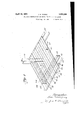
- FIG. 1 is a perspective of a portion of the building construction embodying the present invention
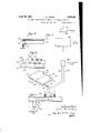
- Fig. 2 a diagrammatic view illustrating the method of wiring forming a part of the present invention
- Fig. 3 a sectional view through one of the flooring conduits taken on the line 33, Fig. 1;
- the ducts of themselves do not function as floor members and merely serve as conduits through electric wiring may be run to provide electrical service, whether it be light, telephone, or 0th service, at different points in the ofiices or floors throughout the building.
- These ducts have been located at relatively wide intervals across the floor, as for example every four to six feet, and in some instances at greater distances and have been in practice provided with outlets usually in the form of short pipe sections designed to extend upwardly through the concrete floor and to receive a special fitting if electrical service is desired at the particular location of the outlet. It has been the practiceto locate such outlets at intervals of a few feet along the several ducts.
- a building construction is provided with a flooring having a plurality of conduits an with electric conductors located in said conduits and from which electrical apparatus within the building may be supplied with current.
- the flooring is preferably composed of a plurality of preformed units, eac including a corrugated sheet and with cerunits arranged end to end with the corrugations in substantial alignment and forming substantially continuous conduits extending from one part of the building to another.
- the invention is incorporated in a building construction of the type having a metal framework provided parallel side and en with substantially panels at each of th furnished to desired locations within the building.
- duits may and preferably will be ith at; desired locations,
- Fig. 1 the longitudinal the side members of th cross girders 12 and t girders 12 form e panels 14, and the e intermediate beams connecting the longitudinal girders 12 form the endmembers of the panels 14.
- Each panel lat has co-operating with it a sheet metal flooring, which is composed of a plurality of units capable of being fabricated in the shop, transported tothe job and laid inplace.
- ach floor unit comprises a sheet metal upper member 18 and a corrugated sheet metal under which is spot to the under
- the under-sheet metal member 15) is preferably provided with substantially V-beam corrugations which may be of varying depths according to the load to be carried, and the upper sheet metal member 18 is preferably Width as to rethe manner represented in Fig. 1
- the sheet metal units when laid in place are designed to have their sides in contact or in close proximity to one another and when thus positioned the upper metal sheets of contiguous units may he spot welded together, so as to provide the panel with a sheet metal flooring having a unitary upper sheet metal member of substantially the area of the panel, and having attached to its under side a plurality of independent or separate corrugated sheet metal load-supporting m cmbers which extend lengthwise of the panel for substantially the length thereof substantially parallel with one another.
- the sheet metal members 18, 19 forming the units are in accordance with the present invention arranged so that the corrugations of one are in substantial alignment with the ting relation or, if the ends thereof are spaced apart, the intervening space is preferably closed by a suitable closure member preferlieet metal and of a shape to corre spond to the corrugations.
- conduits indicated generally at 33 are provided, which extend in one direction such as lengthwise of the building from one part thereof to another and which in some instances may extend from one side of the building to the other. These conduits 33, it will are spaced a relatively and in practice may be centers.
- tie flooring having the multiplicity of conduits 33 is provided with electrical conductors in selected ones of the eond nits, and from hich conductors current may be supplied apparatus within the building. Provision is made for running electric wiring through some of said conduits to provide electric service to desired locations with in the building, such for example as floor outlets, ceiling outlets, or outlets located in the As diagrammatically illustrated in be observed,
- the electrical service tothe building may be represented by the line 37 passing through the usual meters 38 and main switchboard 39, and thence to a local circuit panel 40 located at one of the floors of the building.
- a local circuit panel 40 located at one of the floors of the building.
- two supply lines 42, 44 which may be for the same or different kinds of electrical service, are represented as being run into a transverselyextend'ed box or conduit 46, the latter being provided with two compartments 47, 49, each in open communication with the floor conduits, and within which the supply lines 42 and 44 respectively may be located.
- the box or conduit 46 may be provided with a door 50 for affording access to the interior of the compartments 47 49 and to enable lead lines 51, the supply lines 42, 44, respectively, as-illustrated 1n Figs.2 and 3. With the usual snake the lead lines 51, 52
- the outlets may be installed after the finished floor has been erected, and after the desired locations of the outlets have been determined upon, it being merely necessary to drill down through the concrete flooring an through the top of the floor conduits.
- stances I may prefer to operatively support the flooring upon angle shelves 60 such as is illustrated in Figs. 4 and stances the flooringwill preferably be supported so that the intermediate corrugations 59 of the type of flooring illustrated in Figs. 4 and 5 are positioned above the top of the I-beam and suitable cover members 64 may be provided to close the corrugations 59 and the electrical conductors may be located in the conduits formed b such intermediate corrugations, as clearly illustrated in Figs. 4 and 5.
- a combination metal floor and wire distributing structure comprising a plurality of connected hollow cells closed in cross section and forming load supporting beams, supporting means for said floor, some of said cells being positioned in alignment and forming substantially continuous unobstructed ducts and provided intermediate the ends thereof for electrical wiring extending into said ducts.
- a combination metal flooring and wire distributing structure comprising a plurality of connected hollow cells closed in cross section and forming load supporting beams, supfor said floor, some of said alignment and forming substantially continuous unobstructed ducts, a transversely extended conduit in open communication with a plurality of the aforesaid hollow cells, an electrical supply line extending through said transverse conduit, electrical wiring connected to said supply line and extended through some of said ducts, said ducts being provided with outlets for said wiring at the desired locations within the building.
- a framework arranged to form floor panels, a metallic flooring supported thereon, said flooring comprising a plurality of prefabricated units, each unit having a plurality oi hollow cells .closed in cross section and forming load supporting b with a lurality of said units arranged end to end with a plurality of said hollow cells in alignment and forming substantially continuous unobstructed ducts, some of said ducts beprovided with outlets for electrical wiring extended into the ducts. 4.
- a combination metal floor and wire distributing structure comprising a plurality of hollow cells closed in cross section and forming load supporting beams, supporting means tor said floor, some of said cells being positioned in alignment and forming substantial,- ly continuous unobstructed ducts and pro vided intermediate the ends thereof with outlets for electrical wiring extended into said ducts.
- a combination metal floor and wire distributing structure comprising a plurality of wiring may be led outwardly from Within such cells.
Landscapes
- Engineering & Computer Science (AREA)
- Architecture (AREA)
- Civil Engineering (AREA)
- Structural Engineering (AREA)
- Installation Of Indoor Wiring (AREA)
- Floor Finish (AREA)
Description
April 1932- J. H. YOUNG 1,855,082
BUILDING CONSTRUCTION AND MEANS FOR WIRING A BUILDING Filed Aug. 26, 1931 2 Sheets-Sheet 1 April 19, 1932. J. H. YOUNG 1,855,082
BUILDING CONSTRUCTION AND MEANS FOR WIRING A BUILDING Laoa/ diva/3- End.
44 O m g a 4 a 7 zve7c0 7- elaborate special wiring atented Apr. v19, 1932 JAMES HO'WARD YOUNG, OF
SYLVANIA PITTSBURGH, ER'ITSON COMPANY, OF PITTSBURGH, PENNSYLVANIA, A CORPORATION PENNSYLVANIA, ASSIGNOR TO B. H. ROB- OF PENN- BUILIDING CONSTRUCTION AND MEANS FOR- WIEING A BUILDING Application filed This invention relates to a building construction and to a method of wiring a building.
In general, one object of the invention is to provide a novel and improved building construction which may be economically erected and the construction of which is adapted to enable electrical service to be furnished to different desired locations in the building wit 1 a maximum flexibility, simplicity, convenience and economy.
Another object of the invention is to provide a novel method of wiring a building for electrical service and by which the service may be economically furnished in a simple, eflicient, and most flexible manner to any desired location in the building.
With these objects in view and such others as may hereinafter appear, the invention consists in the building construction, method of wiring the building and in the various structures, arrangements and combinations parts, hereinafter described and particularly defined in the claims at the end of this specification.
In the drawings illustrating the preferred embodiments of the invention- Fig. 1 is a perspective of a portion of the building construction embodying the present invention;
Fig. 2, a diagrammatic view illustrating the method of wiring forming a part of the present invention;
Fig. 3, a sectional view through one of the flooring conduits taken on the line 33, Fig. 1;
Figs. 4.- and 5, details in side and end elevation respectively of a modified construction of flooring, aswill be described.
In the construction of modern buildings, the general practice in wiring the building has heretofore included the installation 0 ducts under the usual concrete flooring of the building. These wiring ducts have heretofore been made of metal and have been installed after the supporting flooring has been formed an before the finished concrete flooring has been oured. duct system of the prior art l is has generally been referred to as an under- August 26, 1931.
f tain of the Serial N0. 559,425.
floor duct system. The ducts of themselves do not function as floor members and merely serve as conduits through electric wiring may be run to provide electrical service, whether it be light, telephone, or 0th service, at different points in the ofiices or floors throughout the building. These ducts have been located at relatively wide intervals across the floor, as for example every four to six feet, and in some instances at greater distances and have been in practice provided with outlets usually in the form of short pipe sections designed to extend upwardly through the concrete floor and to receive a special fitting if electrical service is desired at the particular location of the outlet. It has been the practiceto locate such outlets at intervals of a few feet along the several ducts.
The expense of installation and the cost of such duct systems add considerably to the cost of the floor, and the number of such ducts is necessarily limited by the expense involved. As a result very definite limits are inherent in these prior under-floor duct systems in point within the building, the serviceis required to more or less adapt the location of his desk, switchboard, or other apparatus, to the location of the outlets at definite intervals in the spaced-apart ducts of the system.
In accordance with the present invention, a building construction is provided with a flooring having a plurality of conduits an with electric conductors located in said conduits and from which electrical apparatus within the building may be supplied with current. The flooring is preferably composed of a plurality of preformed units, eac including a corrugated sheet and with cerunits arranged end to end with the corrugations in substantial alignment and forming substantially continuous conduits extending from one part of the building to another.
In its preferred form, the invention is incorporated in a building construction of the type having a metal framework provided parallel side and en with substantially panels at each of th furnished to desired locations within the building.
duits may and preferably will be ith at; desired locations,
ply line to a tion thereto of the individual wires located in the conduits.
eferring now to the drawings, Which as above stated 10 and horizontal steel members usually gird- The girders 12 and form panels or openings at each floor of the building, a portion of one of which is shown in Fig. 1.
In Fig. 1, the longitudinal the side members of th cross girders 12 and t girders 12 form e panels 14, and the e intermediate beams connecting the longitudinal girders 12 form the endmembers of the panels 14. Each panel lat has co-operating with it a sheet metal flooring, which is composed of a plurality of units capable of being fabricated in the shop, transported tothe job and laid inplace. ach floor unit comprises a sheet metal upper member 18 and a corrugated sheet metal under which is spot to the under The under-sheet metal member 15) is preferably provided with substantially V-beam corrugations which may be of varying depths according to the load to be carried, and the upper sheet metal member 18 is preferably Width as to rethe manner represented in Fig. 1
The sheet metal units when laid in place are designed to have their sides in contact or in close proximity to one another and when thus positioned the upper metal sheets of contiguous units may he spot welded together, so as to provide the panel with a sheet metal flooring having a unitary upper sheet metal member of substantially the area of the panel, and having attached to its under side a plurality of independent or separate corrugated sheet metal load-supporting m cmbers which extend lengthwise of the panel for substantially the length thereof substantially parallel with one another.
The sheet metal members 18, 19 forming the units are in accordance with the present invention arranged so that the corrugations of one are in substantial alignment with the ting relation or, if the ends thereof are spaced apart, the intervening space is preferably closed by a suitable closure member preferlieet metal and of a shape to corre spond to the corrugations.
With this construction a plurality of conduits indicated generally at 33 are provided, which extend in one direction such as lengthwise of the building from one part thereof to another and which in some instances may extend from one side of the building to the other. These conduits 33, it will are spaced a relatively and in practice may be centers.
In accordance with the present invention tie flooring having the multiplicity of conduits 33, is provided with electrical conductors in selected ones of the eond nits, and from hich conductors current may be supplied apparatus within the building. Provision is made for running electric wiring through some of said conduits to provide electric service to desired locations with in the building, such for example as floor outlets, ceiling outlets, or outlets located in the As diagrammatically illustrated in be observed,
.52 to be connected to volving the use 0 Fig. 2, the electrical service tothe building may be represented by the line 37 passing through the usual meters 38 and main switchboard 39, and thence to a local circuit panel 40 located at one of the floors of the building. From the local circuit panel two supply lines 42, 44, which may be for the same or different kinds of electrical service, are represented as being run into a transverselyextend'ed box or conduit 46, the latter being provided with two compartments 47, 49, each in open communication with the floor conduits, and within which the supply lines 42 and 44 respectively may be located. The box or conduit 46 may be provided with a door 50 for affording access to the interior of the compartments 47 49 and to enable lead lines 51, the supply lines 42, 44, respectively, as-illustrated 1n Figs.2 and 3. With the usual snake the lead lines 51, 52
While for purposes of illustration 1 have illustrated in Fig. 2 two supply lines 42, 44, it will'of course be understood sired number of electrical conductors may be extended through the transversely-extended box or conduit 46, and that any desired number of outlets may be provided in any selected number of conduits according to the type and location of electrical service to be furnished. I
The outlets may be installed after the finished floor has been erected, and after the desired locations of the outlets have been determined upon, it being merely necessary to drill down through the concrete flooring an through the top of the floor conduits.
While in Figs. 1 and 2 the corrugated metal flooring is illustrated as resting on top of the supporting I-beams, stances I may prefer to operatively support the flooring upon angle shelves 60 such as is illustrated in Figs. 4 and stances the flooringwill preferably be suported so that the intermediate corrugations 59 of the type of flooring illustrated in Figs. 4 and 5 are positioned above the top of the I-beam and suitable cover members 64 may be provided to close the corrugations 59 and the electrical conductors may be located in the conduits formed b such intermediate corrugations, as clearly illustrated in Figs. 4 and 5.
From the description thus far it will be observed that the present building construction and present method of wiring a building possesses important economic advantages as compared with rior art constructions inseparate wiring ducts.
The multiplicity of conduits formed as a d with outlets that any dep part of the floor afiords maximum flexibility in wiring for any kind of electric service and enable electrical apparatus to be positioned and connections to be made thereto in a most siniipk, economical and practical manner.
ile the preferred embodiments of the invention have been herein illustrated and described, it will be understood that the invention may be embodied in other forms within the scope of'the following claims.
Having thus descr'bed the invention, what is claimed is:
1. In a building construction, in combination, a combination metal floor and wire distributing structure comprising a plurality of connected hollow cells closed in cross section and forming load supporting beams, supporting means for said floor, some of said cells being positioned in alignment and forming substantially continuous unobstructed ducts and provided intermediate the ends thereof for electrical wiring extending into said ducts.
2. In a building constructiomin combination, a combination metal flooring and wire distributing structure comprising a plurality of connected hollow cells closed in cross section and forming load supporting beams, supfor said floor, some of said alignment and forming substantially continuous unobstructed ducts, a transversely extended conduit in open communication with a plurality of the aforesaid hollow cells, an electrical supply line extending through said transverse conduit, electrical wiring connected to said supply line and extended through some of said ducts, said ducts being provided with outlets for said wiring at the desired locations within the building.
3. In a building construction, in combination, a framework arranged to form floor panels, a metallic flooring supported thereon, said flooring comprising a plurality of prefabricated units, each unit having a plurality oi hollow cells .closed in cross section and forming load supporting b with a lurality of said units arranged end to end with a plurality of said hollow cells in alignment and forming substantially continuous unobstructed ducts, some of said ducts beprovided with outlets for electrical wiring extended into the ducts. 4. In a building construction, in combination, a combination metal floor and wire distributing structure comprising a plurality of hollow cells closed in cross section and forming load supporting beams, supporting means tor said floor, some of said cells being positioned in alignment and forming substantial,- ly continuous unobstructed ducts and pro vided intermediate the ends thereof with outlets for electrical wiring extended into said ducts.
5. In a. building construction, in combinameans for the 8.Inabuil tion, a combination metal floor and wire diswise of the conduits and outwardly through tributing structure comprising a plurality of said outlets.
hollow cells closed in cross section and form- 6. In a building construction, in combination, a combination metal floor and wire distributing structure comprising a plurality of wiring may be led outwardly from Within such cells.
continuous unobstructed such aligned side to provide the structure with a relatively ducts, some of said cells being provided with electrical outlets, and a service conduit communicating with said cells and being extended transversely of the units but displaced vertically withrelation thereto.
ed upon the f and comprising a multicellular metallic floor having a relatively urge number of spaced hollow cells closed in cross section, said cells forming a relatively large number of potential wiring ducts and the walls of said cells constituting load supt-he floor structure with a relatively large number of ducts, supporting floor, some of the ducts being Wiring conand through fished lengthults leading into the building which electrical wiring may be In testimony whereof I have signed my name to this specification.
JAMES HOWARD YOUNG.
Priority Applications (1)
| Application Number | Priority Date | Filing Date | Title |
|---|---|---|---|
| US559425A US1855082A (en) | 1931-08-26 | 1931-08-26 | Building construction and means for wiring alpha building |
Applications Claiming Priority (1)
| Application Number | Priority Date | Filing Date | Title |
|---|---|---|---|
| US559425A US1855082A (en) | 1931-08-26 | 1931-08-26 | Building construction and means for wiring alpha building |
Publications (1)
| Publication Number | Publication Date |
|---|---|
| US1855082A true US1855082A (en) | 1932-04-19 |
Family
ID=24233554
Family Applications (1)
| Application Number | Title | Priority Date | Filing Date |
|---|---|---|---|
| US559425A Expired - Lifetime US1855082A (en) | 1931-08-26 | 1931-08-26 | Building construction and means for wiring alpha building |
Country Status (1)
| Country | Link |
|---|---|
| US (1) | US1855082A (en) |
Cited By (8)
| Publication number | Priority date | Publication date | Assignee | Title |
|---|---|---|---|---|
| US2591654A (en) * | 1948-06-23 | 1952-04-01 | Budd Co | Panel joint support |
| US2694475A (en) * | 1948-11-19 | 1954-11-16 | Robertson Co H H | Cellular steel floor |
| US2783639A (en) * | 1952-10-29 | 1957-03-05 | Henry H Werner | Concrete slab and embedded duct structure |
| US2910152A (en) * | 1955-09-01 | 1959-10-27 | Robertson Co H H | Cellular steel floor |
| US5287814A (en) * | 1989-04-14 | 1994-02-22 | Hitachi, Ltd. | Car body of railway rolling stock and method for fabricating car body |
| US20070051127A1 (en) * | 2003-09-26 | 2007-03-08 | Ssw Holding Company, Inc. | Cooling tubes for shelving |
| RU2759524C1 (en) * | 2021-01-18 | 2021-11-15 | Федеральное государственное бюджетное образовательное учреждение высшего образования "Казанский государственный архитектурно-строительный университет" (КазГАСУ) | Steel-reinforced concrete floor |
| RU2785159C1 (en) * | 2022-02-28 | 2022-12-05 | Федеральное государственное бюджетное образовательное учреждение высшего образования "Казанский государственный архитектурно-строительный университет" (КазГАСУ) | Steel-reinforced concrete floor |
-
1931
- 1931-08-26 US US559425A patent/US1855082A/en not_active Expired - Lifetime
Cited By (10)
| Publication number | Priority date | Publication date | Assignee | Title |
|---|---|---|---|---|
| US2591654A (en) * | 1948-06-23 | 1952-04-01 | Budd Co | Panel joint support |
| US2694475A (en) * | 1948-11-19 | 1954-11-16 | Robertson Co H H | Cellular steel floor |
| US2783639A (en) * | 1952-10-29 | 1957-03-05 | Henry H Werner | Concrete slab and embedded duct structure |
| US2910152A (en) * | 1955-09-01 | 1959-10-27 | Robertson Co H H | Cellular steel floor |
| US5287814A (en) * | 1989-04-14 | 1994-02-22 | Hitachi, Ltd. | Car body of railway rolling stock and method for fabricating car body |
| US20070051127A1 (en) * | 2003-09-26 | 2007-03-08 | Ssw Holding Company, Inc. | Cooling tubes for shelving |
| RU2759524C1 (en) * | 2021-01-18 | 2021-11-15 | Федеральное государственное бюджетное образовательное учреждение высшего образования "Казанский государственный архитектурно-строительный университет" (КазГАСУ) | Steel-reinforced concrete floor |
| RU2785159C1 (en) * | 2022-02-28 | 2022-12-05 | Федеральное государственное бюджетное образовательное учреждение высшего образования "Казанский государственный архитектурно-строительный университет" (КазГАСУ) | Steel-reinforced concrete floor |
| RU2801567C1 (en) * | 2023-02-01 | 2023-08-11 | Федеральное государственное бюджетное образовательное учреждение высшего образования "Петербургский государственный университет путей сообщения Императора Александра I" | Composite floor construction |
| RU2839163C1 (en) * | 2024-11-11 | 2025-04-28 | Федеральное государственное бюджетное образовательное учреждение высшего образования "Казанский государственный архитектурно-строительный университет" (КазГАСУ) | Steel-concrete flooring |
Similar Documents
| Publication | Publication Date | Title |
|---|---|---|
| US2877990A (en) | Air conditioning and electrical wire distrubting structure | |
| US1986965A (en) | Wiring duct and fittings | |
| US3583121A (en) | Rigid reticulated bar joist system | |
| US4524698A (en) | Modular rail member for the translation of load-bearing carriages on an overhead track | |
| US1867433A (en) | Building construction | |
| US3453791A (en) | Underfloor electrical raceway crossover unit | |
| US2946413A (en) | Building and combination air and wire distributing structure | |
| US2694475A (en) | Cellular steel floor | |
| US2089893A (en) | Hollow steel building structure | |
| US3074208A (en) | Cellular floor headertrough | |
| US2783639A (en) | Concrete slab and embedded duct structure | |
| US3104060A (en) | Fire extinguishing system and apparatus | |
| US1855082A (en) | Building construction and means for wiring alpha building | |
| US2680775A (en) | Wire distributing system | |
| SE456331B (en) | ROOM UNIT, SPECIFICALLY CABIN OR COTTAGE BY VESSEL | |
| US2125366A (en) | Cross-over duct for multicellular structures | |
| US2041965A (en) | Underfloor wiring conduit system | |
| US2975559A (en) | Wire distributing cellular metal floor | |
| US3197926A (en) | Hanger means for sheet metal sectional roofing and flooring | |
| US2259674A (en) | Wiring conduit and wire distribution system | |
| US1972570A (en) | Metal building panel | |
| US1815447A (en) | Underfloor wiring duct system | |
| US2901062A (en) | Metaldecking | |
| US1986122A (en) | Partition riser | |
| US1530200A (en) | System of wiring conduits for building construction |