US1855081A - Grain shocker - Google Patents
Grain shocker Download PDFInfo
- Publication number
- US1855081A US1855081A US489191A US48919130A US1855081A US 1855081 A US1855081 A US 1855081A US 489191 A US489191 A US 489191A US 48919130 A US48919130 A US 48919130A US 1855081 A US1855081 A US 1855081A
- Authority
- US
- United States
- Prior art keywords
- tray
- assembly
- trays
- shock
- gate
- Prior art date
- Legal status (The legal status is an assumption and is not a legal conclusion. Google has not performed a legal analysis and makes no representation as to the accuracy of the status listed.)
- Expired - Lifetime
Links
- 230000035939 shock Effects 0.000 description 10
- 239000002184 metal Substances 0.000 description 2
- 238000010276 construction Methods 0.000 description 1
- 238000003306 harvesting Methods 0.000 description 1
- 238000000034 method Methods 0.000 description 1
- 230000000630 rising effect Effects 0.000 description 1
Images

Classifications
-
- A—HUMAN NECESSITIES
- A01—AGRICULTURE; FORESTRY; ANIMAL HUSBANDRY; HUNTING; TRAPPING; FISHING
- A01D—HARVESTING; MOWING
- A01D75/00—Accessories for harvesters or mowers
- A01D75/06—Sheaf shockers or stookers
Definitions
- One' of the objects of the presentinvention is to provide improved means for holding 'the duplex trays in a horizontal position lrelatively to the frame during the filling operation.
- a further object is to furnish a mechanism of this character, comprising novel means for releasing the trays to allow dumping of one tray and the bringing of the other tray into uppermost position.
- a further object is to provide Vthe machine frame with rearwardly and upwardly inclined slots to accommodate the tray axle, so that the trays will ride up and over a deposited shock, while the machine is moving forward, without liability of toppling the shock over.
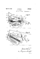
- Fig. 1 is a side elevation of my improved shocker.
- Fig. 2 is a transverse. vertical sectional view of the same on the line 2 2 of Fig. 1.
- w" Fig. 3 is a longitudinal vertical sectional view with the dumping trays in horizontal position.
- Fig. 4 is a similar view but showing the releasing mechanism actuated and the upper- Vmost tray in the process of dumping.
- 5 designates a horizontally disposed U-shaped frame consisting of frontcross bars 6 andside bars 7.
- Suitable spacing blocks 8 join the side bars to the vertical side walls 9, and between these Y side walls and the side bars, supporting wheels 10 are arranged to rotate on stub axles 11.
- Each side wall hasV an upwardly and rearwardly inclined slot 12, in which are journaled the ends of the dumping tray axle 13, 1
- the dumping tray assembly consists of a upper tray 15 and a lower tray 16, each having side walls 17 and a rear wall 18, the front of each tray being open when it is uppermost.
- the bottoms of the trays are rigidly connected to the shaft 13 and are spaced apart by blocks 19.
- each tray projects outwardly beyond the wall 18, and its edge is reinforced by a U- shaped metal strip 20.
- the rearl end of lthe uppermost tray 15 is prevented from'rising by a gate 21 which extends between the side of the side walls.
- a spring 24 normally holds the gate 21 in contact with the rear ends of the walls 9 to form amovable abutmentV against which the rear end of the uppermost tray bears.
- the front end of the tray assembly is prevented from risingbyfmeans of strap or leaf springs 25. As shown in Fig. 2, there is one of these leaf springs at each side of the machine, and its upper end is hooked over an upper edge of the wall 9, as at 26, and secured to the wall by screws or the-like 27 These springs 25 converge downwardly, buttheir lower ends can move toward the walls 9 when they are forced to do so by either one of the projecting ends of the tray assembly.4
- the tray :assembly willofy course be obstructed vby the deposited shock, 'so vvthat the tray assembly tends toswing in a clock-wise ⁇ direction to bring'the lowermost tray tothe uppermost position,'1 but in order to prevent the shock from being'knoeked over, the axle 13 will ride upI the slots l2, whereby the tray assem- @'25 vblywi-llrise'and clear the depositedV shock,
- Thebvariousgparts of the device may be 'inade of any suitable'materiahbut Irpref'ertogmake the tray assembly of sheet metal.
- a grain shocker comprising-fa wheel supported body, a 'dumpingtray-assemblyfrotatably mounted in theY bodyf-and comprising a upper and? lower trays,-ach -trayybeingprovid'edwith ,a projecting end, arid v'resiliei'it means on 'the body lformingfyabutments automatically engageable with eitherl of-saidprd Yjecting ends when it is -at-theroifit'of the "Q0 tray assembly for preventing counter-clockwise rotation ⁇ of the tray- ⁇ assemblyl fin a -direction toward the rearendof the body.
- a lgrain-shocker comprising'a wheelfsupported body, a- Idum-ping tra'y assembly -frof I tatably mounted in the body 'and com'pri'sing Auppe'r and ilo'wer' trays,I 'eachx trayibeingprovided with 'a projecting endyf-andfyielding means on ythe body *forming- "abutments-f en?
Landscapes
- Life Sciences & Earth Sciences (AREA)
- Environmental Sciences (AREA)
- Warehouses Or Storage Devices (AREA)
Description
April 19, 1932. R. WOODS 1,855,081
GRAIN SHOCKER Filed oct. le, 195o 2 sheets-sheet 1 fly/9.2.
R. WOODS GRAIN SHOCKER April 19, 1932.
Filed OCT. 16, 1930 2 Sheets-Sheet 2 S14/uente@ Patented Apr. 19, 1932 UNITED vSTATES PATENT- OFFICE ROBERT' WOODS, 0F GRAND FORKS; NORTH DAKOTA GRAIN sHocxER Application filed October 16, 1930.l SeriaI No. 489,191. l
10 so that the uppermost one after being loaded with a shock from the harvesting machine, may dump the shock and set the same upright on the ground, in such manner that the lower dumping tray will come uppermost to receive 15 the sheaves which are to form the next shock.
Y One' of the objects of the presentinvention is to provide improved means for holding 'the duplex trays in a horizontal position lrelatively to the frame during the filling operation.
A further object is to furnish a mechanism of this character, comprising novel means for releasing the trays to allow dumping of one tray and the bringing of the other tray into uppermost position.
A further object is to provide Vthe machine frame with rearwardly and upwardly inclined slots to accommodate the tray axle, so that the trays will ride up and over a deposited shock, while the machine is moving forward, without liability of toppling the shock over.
With the foregoing objects outlined and with other objects in view which will appear as the description proceeds, the invention consists in the novel features hereinafter described in detail, illustrated in the accompanying drawings, and more particularly pointed out in the appended claims.
In the drawings,
Fig. 1 is a side elevation of my improved shocker. Y
Fig. 2 is a transverse. vertical sectional view of the same on the line 2 2 of Fig. 1.
w" Fig. 3 is a longitudinal vertical sectional view with the dumping trays in horizontal position. j
Fig. 4 is a similar view but showing the releasing mechanism actuated and the upper- Vmost tray in the process of dumping.
Referring to the drawings, 5 designates a horizontally disposed U-shaped frame consisting of frontcross bars 6 andside bars 7.
Each side wall hasV an upwardly and rearwardly inclined slot 12, in which are journaled the ends of the dumping tray axle 13, 1
and a suitable abutment collar 14`is fixed to each of the end portions of thelaxle to bear against the sides 9 and limit the lengthwise movement of said axle. i The dumping tray assembly consists of a upper tray 15 and a lower tray 16, each having side walls 17 and a rear wall 18, the front of each tray being open when it is uppermost. Y The bottoms of the trays are rigidly connected to the shaft 13 and are spaced apart by blocks 19.
Asbest shown in Figs. 1, 3 and 4, the bottom of each tray projects outwardly beyond the wall 18, and its edge is reinforced by a U- shaped metal strip 20. The rearl end of lthe uppermost tray 15 is prevented from'rising by a gate 21 which extends between the side of the side walls. y
A spring 24 normally holds the gate 21 in contact with the rear ends of the walls 9 to form amovable abutmentV against which the rear end of the uppermost tray bears.`
The front end of the tray assembly is prevented from risingbyfmeans of strap or leaf springs 25. As shown in Fig. 2, there is one of these leaf springs at each side of the machine, and its upper end is hooked over an upper edge of the wall 9, as at 26, and secured to the wall by screws or the-like 27 These springs 25 converge downwardly, buttheir lower ends can move toward the walls 9 when they are forced to do so by either one of the projecting ends of the tray assembly.4
To permit the gate 21 to be opened from 'a remote point,'one edge-of the gate'is provided/,with an `upstanding lever 28 thatis walls 9, and is hinged at 22 to a bar 23which has its ends rigidly connected to the rear ends een connected to a rope 29 leading to the pointl where the operator is located.
In operation, we will assume that the tray assembly is in the position shown in Figs. 1 to 3 inclusive, and that the device is hooked up with a harvester in the known manner. As the device moves forwardly over the field, with the harvester,` the grain lsheaves kwill be deposited in the uppermost tray l5, and when a suflicient numberv ofsheaves has been deposited to form a 'shoclnthe peratorfpulls the rope 29 to open the gate 2l. As this Y releases the rear end of the inoperm'stv tray, the tray assembly willv moveforwardly and downwardly, as shown in 4,'and`vthe shock will be 'deposited on-the ground. Now, asthemachine moves forward, the tray :assembly willofy course be obstructed vby the deposited shock, 'so vvthat the tray assembly tends toswing in a clock-wise` direction to bring'the lowermost tray tothe uppermost position,'1 but in order to prevent the shock from being'knoeked over, the axle 13 will ride upI the slots l2, whereby the tray assem- @'25 vblywi-llrise'and clear the depositedV shock,
l,and at the sametime, therear edge of the tray which wasmoriginally uppermost, will havev its ends come' in contact with the leaf springs 25, so as to compress the latter and '30 force them towards the walls 9, until 'the tray end passes'beneath the lower edges ofi-the springs 425. In the meantime, the operator `will, have released the` cord 29, Eand tliegate 2 1l will be in the positionY shown in'Fig. 3, Vwith thefresult that the projecting end 2O of the tray, which was originally lowermost, will come in'contact with the lower edge of -the gate and be halted thereby. The original l'owermo'st tray is now inthe properposition toreoeive the sheaves toform'the next shock.
Thebvariousgparts of the device may be 'inade of any suitable'materiahbut Irpref'ertogmake the tray assembly of sheet metal.
Y Y rom they foregoing it is believedthat the construction, operation and advantages of the invention maybe .readily understood,A and I am aware that changes may be made `in they ldetailsdisclosed, without departingfrom the spirit of the invention, as expressed in the olaims. w, a A, ,y VVhatI claim and desire ters 'Pat'ntis: t H
l. 'shocker'comprising awheel siip- "polrtd: body t'provided with "upwardly 4and toI secure by rLety= rearwardly 1 'inclined"giiidways, ,a tray [as sammy having an: mgmt-ambie and snaai-)1e inl said guideways; andv releasable means' for rnorniallyY holding Athe* trayas'sembly in ai hori- -ypor-ted' bdy,a tray as'se'mblypivotallyriibunte'd-innthe body and consisting of upper'fand lower trays, eachI tray-having afproje'clting position, the last mentioned means compris- 'ing' an elastic`elenriifhaving one of its ends 'mounted on'fsaid` shaft and iincludingupperp end portion, a hinged gate on the body forming a Amovable abutment cooperating'with 75 the. pojectiri'g'nds "of the trays to limit the upward movement of the tray assembly, and means for normally holding the gate in closed connected to `the gate zand its otherendconnected to the-body.
4. A grain shocker comprising-fa wheel supported body, a 'dumpingtray-assemblyfrotatably mounted in theY bodyf-and comprising a upper and? lower trays,-ach -trayybeingprovid'edwith ,a projecting end, arid v'resiliei'it means on 'the body lformingfyabutments automatically engageable with eitherl of-saidprd Yjecting ends when it is -at-theroifit'of the "Q0 tray assembly for preventing counter-clockwise rotation` of the tray-` assemblyl fin a -direction toward the rearendof the body.'
5. A lgrain-shocker comprising'a wheelfsupported body, a- Idum-ping tra'y assembly -frof I tatably mounted in the body 'and com'pri'sing Auppe'r and ilo'wer' trays,I 'eachx trayibeingprovided with 'a projecting endyf-andfyielding means on ythe body *forming- "abutments-f en? gageable with either of said projecting endswg when 'it isv at Vthe front 'ofnl thetray assenibly for preventing coiint-erclockswise- Vrotatoniof the tray `assembly in 4a directionI itowa'rd-the rear end of"thefbody, saidyieldirgv-meams comprising leaf springs secured tovthe'f-sides" of the body. I
"6. A grain "shoclrrcomprising fa "hori- Zontally 'disposed` U'shapiid` frame havinga cross bar-'at'fits lfront endga Ulshaped`v body rigidly connected 'to thefframeandfhaving' a cross-'bar'at' itsrear'end, wheels supporting said frame and body, a rotatablesshaftfcarried by thefbody, a .dumping -ray assembly and Vlowerl trays provided*withirontfand rear extensions, a spring clbsedigateinorma-lly engaging the'rear'eXtension and preventing upwardmovement ofthe rear-'en-dfof-fthetray assembly, and yielding Straps supported 'by the sides of the body and eng-aging the rbnt extension 'for 'preventing upwardmfove'ient of the front end of the tray assembly. Y W
In testimony whereof {I'ihave signed this speciiication.
Y Ro-Bmifrwoons, 125'
Priority Applications (1)
| Application Number | Priority Date | Filing Date | Title |
|---|---|---|---|
| US489191A US1855081A (en) | 1930-10-16 | 1930-10-16 | Grain shocker |
Applications Claiming Priority (1)
| Application Number | Priority Date | Filing Date | Title |
|---|---|---|---|
| US489191A US1855081A (en) | 1930-10-16 | 1930-10-16 | Grain shocker |
Publications (1)
| Publication Number | Publication Date |
|---|---|
| US1855081A true US1855081A (en) | 1932-04-19 |
Family
ID=23942778
Family Applications (1)
| Application Number | Title | Priority Date | Filing Date |
|---|---|---|---|
| US489191A Expired - Lifetime US1855081A (en) | 1930-10-16 | 1930-10-16 | Grain shocker |
Country Status (1)
| Country | Link |
|---|---|
| US (1) | US1855081A (en) |
-
1930
- 1930-10-16 US US489191A patent/US1855081A/en not_active Expired - Lifetime
Similar Documents
| Publication | Publication Date | Title |
|---|---|---|
| US3113819A (en) | Car top carrier | |
| US1855081A (en) | Grain shocker | |
| US968828A (en) | Garbage-tank. | |
| US1832999A (en) | Animal feeding device | |
| US1831026A (en) | Hand cart for milk cans | |
| US1708376A (en) | Apparatus for handling snow | |
| US570400A (en) | Thomas hill | |
| US2057833A (en) | Dumping body for automobile trucks | |
| US382787A (en) | Dumping-wagon | |
| US908633A (en) | Truck. | |
| DE366884C (en) | Tilting device for loading boxes of motor vehicles that are arranged on the underframe in two rows next to one another and independently of one another | |
| DE462257C (en) | Box tipper | |
| US1554313A (en) | Safety appliance | |
| US1417125A (en) | Hayrack | |
| US1345238A (en) | Stock-loading chute | |
| US2812030A (en) | Motor vehicle fuel tank | |
| US1014579A (en) | Attachment for wagon-bodies. | |
| US1528688A (en) | Dump body | |
| US1380033A (en) | Fruit receiving and conveying device | |
| US1366666A (en) | Dumping-truck | |
| US1143308A (en) | Dumping-wagon. | |
| US1502337A (en) | Coaster wagon | |
| US1329101A (en) | Dumping-body for trucks | |
| US1412238A (en) | Stacker for harvesters | |
| US1816251A (en) | Packing machine |