US1855065A - Cultivator - Google Patents
Cultivator Download PDFInfo
- Publication number
- US1855065A US1855065A US483106A US48310630A US1855065A US 1855065 A US1855065 A US 1855065A US 483106 A US483106 A US 483106A US 48310630 A US48310630 A US 48310630A US 1855065 A US1855065 A US 1855065A
- Authority
- US
- United States
- Prior art keywords
- beams
- sections
- bars
- arm
- cultivator
- Prior art date
- Legal status (The legal status is an assumption and is not a legal conclusion. Google has not performed a legal analysis and makes no representation as to the accuracy of the status listed.)
- Expired - Lifetime
Links
- 241000196324 Embryophyta Species 0.000 description 7
- 239000002184 metal Substances 0.000 description 2
- 229910052751 metal Inorganic materials 0.000 description 2
- 241000526657 Microchloa Species 0.000 description 1
- 208000036366 Sensation of pressure Diseases 0.000 description 1
- 229910000831 Steel Inorganic materials 0.000 description 1
- 229910000754 Wrought iron Inorganic materials 0.000 description 1
- 230000004075 alteration Effects 0.000 description 1
- 238000010276 construction Methods 0.000 description 1
- 230000000149 penetrating effect Effects 0.000 description 1
- 238000005096 rolling process Methods 0.000 description 1
- 239000010959 steel Substances 0.000 description 1
Images
Classifications
-
- A—HUMAN NECESSITIES
- A01—AGRICULTURE; FORESTRY; ANIMAL HUSBANDRY; HUNTING; TRAPPING; FISHING
- A01B—SOIL WORKING IN AGRICULTURE OR FORESTRY; PARTS, DETAILS, OR ACCESSORIES OF AGRICULTURAL MACHINES OR IMPLEMENTS, IN GENERAL
- A01B63/00—Lifting or adjusting devices or arrangements for agricultural machines or implements
- A01B63/14—Lifting or adjusting devices or arrangements for agricultural machines or implements for implements drawn by animals or tractors
- A01B63/24—Tools or tool-holders adjustable relatively to the frame
- A01B63/26—Tools or tool-holders adjustable relatively to the frame by man-power
Definitions
- This invention relates to harrows or cultivators and, among other objects, aims to provide an improved, manually operated, double side harrow or cultivator having provision for various kinds of adjustments so it may be used for different kinds of culti vation on rows or beds of any height and width and means whereby the operator may easily dodge plants or obstacles by manipulating the handles,
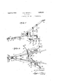
- Fig. 1 is a side elevation of a harrow embodying the invention
- Fig. 2 is a top plan view
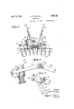
- Fig. 3 is a front end elevation
- Fig. 4 is a fragmentary sectional view through one of the beams and showing a guide arm
- Fig. 5 is a fragmentary top plan View of one of the bars.
- the harrow there shown is preferably made of two sections each having a wooden beam 10 to which tooth bars 11 are adjustably connected at their rear ends.
- the forward ends of the beams are shown as having bent steel draw bars 12 pivotally and loosely connected for universal movement by means of a bolt 13 so that the sections are movable or adjustable both vertically and horizontally with respect to each other.
- To the forward ends of the draw bars 12 are connected ordinary clevises 14 carrying a ring 15 on which is secured a hitching hook 16 (Fig. 1).
- the tooth bars are preferably made of metal and are shown as being secured to the beams by means of bolts 17
- the arrangement is such that the'nut on either of these, bolts may be unscrewed so'that the-tooth bars may be ad justed at different angles relative to the beams.
- An arcuate arm 18 having a series of holes 19 is conveniently secured to the upper sides of the bars and a bolt 20 als passing through each beam is adapted toengage the arms through one of the holes.
- Each of the bars has openings to receive round shanks 21 of harrow or cultivator teeth 22 and the shanks are adapted to be adjustably secured in place by means of set screws 23 (Fig. 5).
- the arrangement is I such that the teeth maybe very easily addirt and to pene- 7 usted to throw more or less trate to the desired depth in different types of beds.
- an ordinary handle 24 To each of the beams 10 is connected an ordinary handle 24.
- the ends of the handles are secured to the front portions of the beams by bolts 25 which are also utilized to secure the draft bars to the beams;
- the handles are maderigid with respect to the beams by'means of suitable braces 26 and 27 on each side.
- braces are conveniently made of strap metal or flat bar iron and one of them for each handle is secured to the top of the beam near the rear end to make the construction more rlgid.
- the angularity of the sections can be by loosening the bolt 31 and again clamping the lock joint ortoothed segments together, thus bringing the teeth or plows, as the case may be, more nearly in the same plane so as to work more or less fiat row beds.
- the outer teeth of each section willbe lowered below the level of the inner .or adjacent teeth so that they will cut or penetrate to the same depth on the sides of relatively high beds.
- the teeth and the tooth bars may be easily and quickly adjusted so as to throw more or less dirt toward the plants. Such adjustment is highly desirable because very small plants require little or no dirt, while larger plants need .some dirt thrown around them to cover small grass in the rows.
- the improved adjustable guide enables the harrow sections to maintam the same relative positions and provides for quick and easy adjustment by the operator to dodge plants and obstacles that may be in the beds of the sections.
- the adjustments of the tooth bars and of the teeth with respect to the bars as well as the angular adjustment made possible by the guide arm enable the implement to be used for practically any kind of cultivation.
- the design is such that either section of the harrow may be separated from the other and used alone'in rough ground after making a few simple and quick alterations such as adding another handle and substituting an ordinary clevis for the draw bar.
- the parts can be manufactured at relatively low cost and they may be assembled and adjusted by any ordinary mechanic. There are no delicate parts apt to break or get out of order in a short while'and the operation is easily understood.
- I v I 1. In combination with a cultivator composed of separate sections having a universal connection to eachv other at their forward ends; an adjustable guiding arm on one'of the sections; and a fixed guide member on the other section cooperating withsaid armwto permit and maintain vertical angular adjustment of the sections and to-permit the sections to be moved laterally with respect to each other to dodge plants and obstacles.
- a pair of beams loosely and pivotally connected at their forward ends to permit universal movement and each carirymg a separate cultivator section ad ustably connected thereto; a handle connected to each beam; a bracket arm secured to one of the beams and projecting abov'e-theother beam; a guiding member secured to'said other beam and cooperating with said arm to-permitlateral adjustment of the beams; and adjustable means'whereby said-armiand guiding member maintain the cultivator sections in substantially the same vertical angular relation with respect to each other when they are adjusted laterally by the handles.
- guiding arm adj ustably secured to said brackst and projecting over the other beam; and a fixed guiding 'member for said arm secured to said other beam and having spaced pairs of anti-friction rollers cooperating with said guiding arm whereby to maintain the same vertical angular relation between the harrovv sections for all positions of lateral adjustment thereof.
Landscapes
- Life Sciences & Earth Sciences (AREA)
- Zoology (AREA)
- Engineering & Computer Science (AREA)
- Mechanical Engineering (AREA)
- Soil Sciences (AREA)
- Environmental Sciences (AREA)
- Soil Working Implements (AREA)
Description
A ril 19, 1932. M. G. MITCHELL 1,855,065
CULT-IVATOR Filed-Sept. 19, 1950 2 Sheets-Sheet 1 0 VENTbR BY M G. A/fz'i'ckell A TTORNEYJ' April 19, 1932.
M. G. MITCHELL CULTIVATOR 2 Sheets-Sheet 2 Filed Sept. 19, 1950 49 INVENTOR Ma/mzc eu,
A TTORNEYJ Patented Apr. 19, 1932 MARSHALL G. MITCHELL, OF LOUISVTLLE, MISSISSIPPI CULTIVATOR Application filed September 19, 1930. Serial No. 483,106.
This invention relates to harrows or cultivators and, among other objects, aims to provide an improved, manually operated, double side harrow or cultivator having provision for various kinds of adjustments so it may be used for different kinds of culti vation on rows or beds of any height and width and means whereby the operator may easily dodge plants or obstacles by manipulating the handles,
Other aims and advantages of the invention will appear in the specification when considered in connection with the accompanying drawings, wherein:
Fig. 1 is a side elevation of a harrow embodying the invention;
Fig. 2 is a top plan view;
Fig. 3 is a front end elevation;
Fig. 4 is a fragmentary sectional view through one of the beams and showing a guide arm; and
Fig. 5 is a fragmentary top plan View of one of the bars.
Referring particularly to the drawings, the harrow there shown is preferably made of two sections each having a wooden beam 10 to which tooth bars 11 are adjustably connected at their rear ends. The forward ends of the beams are shown as having bent steel draw bars 12 pivotally and loosely connected for universal movement by means of a bolt 13 so that the sections are movable or adjustable both vertically and horizontally with respect to each other. To the forward ends of the draw bars 12 are connected ordinary clevises 14 carrying a ring 15 on which is secured a hitching hook 16 (Fig. 1). The front ends of the draw bars are bent outwardly at such angles that the draft or pull on them through the clevises will tend to swing the beams away from each other and thereby equalize the inward or closing pres sure caused by the harrow teeth penetrating the ground at different depths. Thus, the sections and their teeth will remain the same distance apart until the, operator applies adjusting pressure tothem. I p
In this instance, the Wooden beams 10 nor- PATENT OFFICE,
mally lie in planes at an angle to each other, i
this being accomplished by twisting the draft bars 12 as indicated in F 2. The tooth bars are preferably made of metal and are shown as being secured to the beams by means of bolts 17 The arrangement is such that the'nut on either of these, bolts may be unscrewed so'that the-tooth bars may be ad justed at different angles relative to the beams. An arcuate arm 18 having a series of holes 19 is conveniently secured to the upper sides of the bars and a bolt 20 als passing through each beam is adapted toengage the arms through one of the holes.
Each of the bars has openings to receive round shanks 21 of harrow or cultivator teeth 22 and the shanks are adapted to be adjustably secured in place by means of set screws 23 (Fig. 5). The arrangement is I such that the teeth maybe very easily addirt and to pene- 7 usted to throw more or less trate to the desired depth in different types of beds.
To each of the beams 10 is connected an ordinary handle 24. In this example, the ends of the handlesare secured to the front portions of the beams by bolts 25 which are also utilized to secure the draft bars to the beams; Further, the handles are maderigid with respect to the beams by'means of suitable braces 26 and 27 on each side. braces are conveniently made of strap metal or flat bar iron and one of them for each handle is secured to the top of the beam near the rear end to make the construction more rlgid.
To enable the harrow to be adjusted man- I A These I "by-the distance from the lock joint to the connecting bolt 13 of the draft bars, the arrangement being such that the beams may I be swung inwardly or outwardly about the .7 bolt 13 as a center and both beams will be so guided that the teeth of the harrow sections will move in substantially the same angular relation to fit the row of plants or bed. Further, the arm 29 works freely between the rollers so as to provide very easily a sliding or rolling movement when the operator works the handles. The end of the arm 29 is shown as havinga stop member in the form of a pair of nuts 34 threaded on a transverse bolt 35 so as to prevent the sections from being so far separated as to disengage theguide from the arm. I 30 varied by adjusting the guide arm 29. It
, can be raised The angularity of the sections can be by loosening the bolt 31 and again clamping the lock joint ortoothed segments together, thus bringing the teeth or plows, as the case may be, more nearly in the same plane so as to work more or less fiat row beds. By'adjusting the arm the other way, the outer teeth of each section ,willbe lowered below the level of the inner .or adjacent teeth so that they will cut or penetrate to the same depth on the sides of relatively high beds. Furthermore, the teeth and the tooth bars may be easily and quickly adjusted so as to throw more or less dirt toward the plants. Such adjustment is highly desirable because very small plants require little or no dirt, while larger plants need .some dirt thrown around them to cover small grass in the rows.
From the foregolng description, it will be understood that the improved adjustable guide enables the harrow sections to maintam the same relative positions and provides for quick and easy adjustment by the operator to dodge plants and obstacles that may be in the beds of the sections. Furthermore,
the adjustments of the tooth bars and of the teeth with respect to the bars as well as the angular adjustment made possible by the guide arm enable the implement to be used for practically any kind of cultivation. Moreover, the design is such that either section of the harrow may be separated from the other and used alone'in rough ground after making a few simple and quick alterations such as adding another handle and substituting an ordinary clevis for the draw bar. The parts can be manufactured at relatively low cost and they may be assembled and adjusted by any ordinary mechanic. There are no delicate parts apt to break or get out of order in a short while'and the operation is easily understood.
Obviously, the present invention is not restricted to the particular embodiment thereof herein shown and described. Moreover, it is not indispensable that all the features of the invention be used conjointly, since they may be employed advantageously in various combinations and sub-combinations.
What is claimed is: I v I 1. In combination with a cultivator composed of separate sections having a universal connection to eachv other at their forward ends; an adjustable guiding arm on one'of the sections; and a fixed guide member on the other section cooperating withsaid armwto permit and maintain vertical angular adjustment of the sections and to-permit the sections to be moved laterally with respect to each other to dodge plants and obstacles.
2. In combination with an implement of the classdescribed, a pair of beams loosely and pivotally connected at their forward ends to permit universal movement and each carirymg a separate cultivator section ad ustably connected thereto; a handle connected to each beam; a bracket arm secured to one of the beams and projecting abov'e-theother beam; a guiding member secured to'said other beam and cooperating with said arm to-permitlateral adjustment of the beams; and adjustable means'whereby said-armiand guiding member maintain the cultivator sections in substantially the same vertical angular relation with respect to each other when they are adjusted laterally by the handles.
guiding arm adj ustably secured to said brackst and projecting over the other beam; and a fixed guiding 'member for said arm secured to said other beam and having spaced pairs of anti-friction rollers cooperating with said guiding arm whereby to maintain the same vertical angular relation between the harrovv sections for all positions of lateral adjustment thereof.
4. In a cultivator of the class described,
a pair of beams; harrowsections carried by the beams; draw bars'on the beams loosely connected to each other at their forward ends to permit the harrow sections to be sepa rated laterally to dodge obstacles; adjustable;
means to maintain thesamev-ertical angular ture.
MARSHALL G. MITCHELL.
Priority Applications (1)
| Application Number | Priority Date | Filing Date | Title |
|---|---|---|---|
| US483106A US1855065A (en) | 1930-09-19 | 1930-09-19 | Cultivator |
Applications Claiming Priority (1)
| Application Number | Priority Date | Filing Date | Title |
|---|---|---|---|
| US483106A US1855065A (en) | 1930-09-19 | 1930-09-19 | Cultivator |
Publications (1)
| Publication Number | Publication Date |
|---|---|
| US1855065A true US1855065A (en) | 1932-04-19 |
Family
ID=23918683
Family Applications (1)
| Application Number | Title | Priority Date | Filing Date |
|---|---|---|---|
| US483106A Expired - Lifetime US1855065A (en) | 1930-09-19 | 1930-09-19 | Cultivator |
Country Status (1)
| Country | Link |
|---|---|
| US (1) | US1855065A (en) |
Cited By (1)
| Publication number | Priority date | Publication date | Assignee | Title |
|---|---|---|---|---|
| US2694393A (en) * | 1951-07-11 | 1954-11-16 | William E Simpson | Weed burner |
-
1930
- 1930-09-19 US US483106A patent/US1855065A/en not_active Expired - Lifetime
Cited By (1)
| Publication number | Priority date | Publication date | Assignee | Title |
|---|---|---|---|---|
| US2694393A (en) * | 1951-07-11 | 1954-11-16 | William E Simpson | Weed burner |
Similar Documents
| Publication | Publication Date | Title |
|---|---|---|
| US1855065A (en) | Cultivator | |
| US3131775A (en) | Apparatus for earth working | |
| US1865800A (en) | Cultivator | |
| US514210A (en) | Cultivator | |
| US31305A (en) | Improvement in cultivators | |
| US316886A (en) | Cultivator | |
| US580250A (en) | Cultivator | |
| US192060A (en) | Improvement in cultivators | |
| US1381393A (en) | Cultivator | |
| US140724A (en) | Improvement in cultivators | |
| US928079A (en) | Cultivator. | |
| US386443A (en) | Geoege wiaed | |
| US1091760A (en) | Cultivator. | |
| US1558659A (en) | Cultivator | |
| US1143591A (en) | Attachment for cultivators. | |
| US1300596A (en) | Cultivator. | |
| US130337A (en) | Improvement in cultivators | |
| US132842A (en) | Improvement in gang-plows | |
| US1580391A (en) | Garden implement | |
| US422694A (en) | Cultivator | |
| US1948509A (en) | Bush and weed destroying cultivator | |
| US115138A (en) | Improvement in cultivators | |
| US576748A (en) | Cultivator | |
| US890378A (en) | Cultivator. | |
| US2445385A (en) | Coupling |